
O P E R A T I N G I N S T R U C T I O N
GTB6L
Miniature photoelectric sensors


Described product
G6L
GT
B6L
Manufacturer
SICK A
G
Erwin-Sick-Str. 1
79183 Waldkirch
Germany
Production location
SICK Mala
ysia
Legal information
This work is protected by copyright. Any rights derived from the copyright shall be
reserved for SICK AG. Reproduction of this document or parts of this document is only
permissible within the limits of the legal determination of Copyright Law. Any modifica‐
tion, abridgment or translation of this document is prohibited without the express writ‐
ten permission of SICK AG.
The trademarks stated in this document are the property of their respective owner.
© SICK AG. All rights reserved.
Original document
T
his doc
ument is an original document of SICK AG.
Laser
1
2006/42/EC
NO
SAFETY
8025391 / 24.06.2020 | SICK
Subject to change without notice
3

Contents
1 General safety notes......................................................................... 5
2 Notes on UL approval........................................................................ 5
3 Intended use...................................................................................... 5
4 Operating and status indicators...................................................... 5
5 Mounting............................................................................................. 6
6 Electrical installation........................................................................ 7
7 Commissioning.................................................................................. 8
7.1 Alignment.................................................................................................. 8
7.2 Sensing range........................................................................................... 8
7.3 Settings..................................................................................................... 9
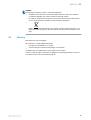
8 Troubleshooting................................................................................. 10
9 Disassembly and disposal............................................................... 10
10 Maintenance...................................................................................... 11
11 Technical specifications................................................................... 12
11.1 Dimensional drawing................................................................................ 12
11.2 Light spot diagram.................................................................................... 13
CONTENTS
4
8025391 / 24.06.2020 | SICK
Subject to change without notice

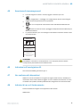
1 General safety notes
■
R
ead the operating instructions before commissioning.
■
Connection, mounting, and configuration may only be performed by trained
s
pecialists.
■
2006/42/EC
NO
S
AFETY
Not a safety component in accordance with the EU Machinery Directive.
■
When commissioning, protect the device from moisture and contamination.
■
T
hese operating instructions contain information required during the life cycle of
the sensor.
EN/IEC 60825-1:2014
IEC60825-1:2007
LASER CLASS 1
Laser
1
Maximum pulse power < 5.95 mW
Puls length: 2 µs
Wavelength: 670 - 690 nm
Complies with FDA performance
standards except for conformance with
IEC 60825-1 Ed. 3,
as described in Laser Notice No. 56,
dated May 8, 2019
ATTENTION
WARNING: Interruption, manipulation or incorrect use can lead to hazardous exposure
due to laser radiation.
2 Notes on UL approval
UL Environmental Rating: Enclosure type 1
3 Intended use
The GTB6L is an opto-electronic photoelectric proximity sensor (referred to as “sensor”
in t
he following) for the optical, non-contact detection of objects. If the product is used
for any other purpose or modified in any way, any warranty claim against SICK AG shall
become void.
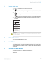
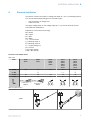
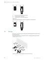
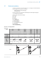
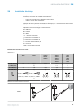
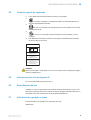
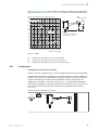
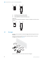
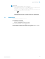
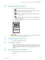
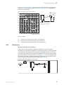
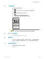
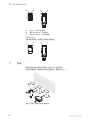
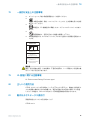
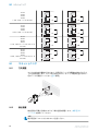
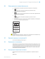
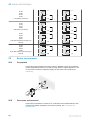
4 Operating and status indicators
Photoelectric proximity sensor with background suppression.
GTB6L-xxx1x
GENERAL SAFETY NOTES 1
8025391 / 24.06.2020 | SICK
Subject to change without notice
5

1
2 3
23
1
1
Potentiometer: sensitivity adjustment
2
Yellow LED indicator: Switching output
3
LED indicator green: supply voltage active
GTB6L-xxx3x
Sensor whic
h it is not possible to set: The sensor is adjusted and ready for operation.
2 3
23
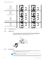
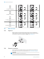
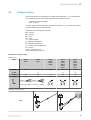
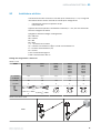
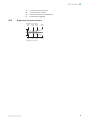
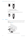
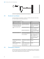
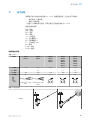
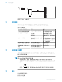
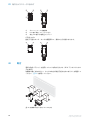
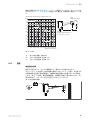
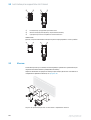
5 Mounting
Mount the sensor using a suitable mounting bracket (see the SICK range of acces‐
sor
ies).
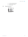
Note the preferred orientation of the sensor relative to the direction of object motion,
refer to figure 1.
Figure 1: Sensor orientation relative to object direction
4 O
PERATING AND STATUS INDICATORS
6
8025391 / 24.06.2020 | SICK
Subject to change without notice

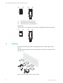
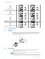
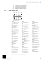
6 Electrical installation
The sensors must be connected in a voltage-free state (U
V
= 0 V
). The following informa‐
tion must be observed depending on the connection type:
– Plug connection: pin assignment
– Cable: wire color
Only apply voltage/switch on the voltage supply (U
V
> 0 V) once all electrical connec‐
tions have been established.
Explanation of connection terminology:
BN = Brown
WH = White
BU = Blue
BK = Black
n. c. = no connection
Q = switching output 1
Q = switching output 2
L+ = supply voltage (Uv)
M = common
L.ON = light operate
D.ON = dark operate
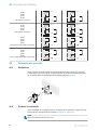
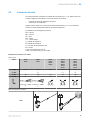
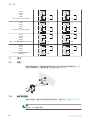
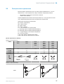
Connection and Output detail:
T
able 1: DC
GTB6L -P1xxx
-N1xxx
-E2xxx
-F2xxx
-P3xxx
-N3xxx
-P5xxx
-N5xxx
-P4xxx
-N4xxx
-P6xxx
-N6xxx
-P7xxx
-N7xxx
-E4xxx
-F4xxx
-E6xxx
-F6xxx
-E7xxx
-F7xxx
1 = BN + (L+) + (L+) + (L+) + (L+) + (L+)
2 = WH -
Q
- n. c.
Q
3 = BU - (M) - (M) - (M) - (M) - (M)
4 = BK Q Q Q Q Q
0.205 mm
2
/
A
WG24
0.205 mm
2
/
AWG24
1
4
3
2
1
4
3
2
1
4
3
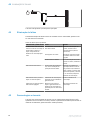
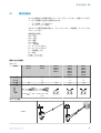
Table 2: Output function
GTB6L
ELECTRICAL INSTALLATION 6
8025391 / 24.06.2020 | SICK
Subject to change without notice
7

-Px1xx
-Px2xx
-Px3xx
-Px4xx
L.ON
, PNP: Q (≤ 100 mA)
+ (L+)
Q
‒
(M)
Load
+ (L+)
Q
‒
(M)
Load
-Px1xx
-Px2xx
-Px5xx
-Px6xx
D.ON
, PNP: Q (≤ 100 mA)
+ (L+)
Q
‒
(M)
Load
+ (L+)
Q
‒
(M)
Load
-Nx1xx
-Nx2xx
-Nx3xx
Nx4xx
L.ON
, NPN Open Collector Q (≤ 100 mA)
+ (L+)
Q
‒
(M)
Load
+ (L+)
Q
‒
(M)
+ (L+)
Q
‒ (M)
Load
-Nx1xx
-Nx2xx
-Nx5xx
-Nx6xx
D.ON
, NPN Open Collector Q (≤ 100 mA)
+ (L+)
Q
‒
(M)
+ (L+)
Q
‒ (M)
Load
+ (L+)
Q
‒
(M)
Load
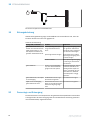
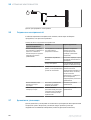
7 Commissioning
7.1 Alignment
Align sensor on object. Select the position so that the red emitted light beam hits the
c
enter of the object. You must ensure that the optical opening (front screen) of the sen‐
sor is completely clear [see figure 0].
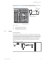
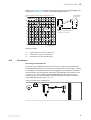
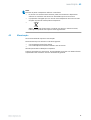
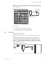
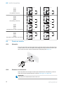
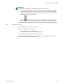
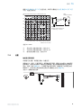
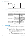
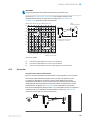
7.2 Sensing range
Adjust the mounting position so that the sensing range and background are within
s
pecification. Refer to see figure 2, page 9.
NOTE
P
lease note the minimum range of 5 mm.
7 COMMISSIONING
8
8025391 / 24.06.2020 | SICK
Subject to change without notice

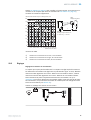
Use see
table 2, page 7 to check the function. If the switching output fails to behave in
accordance with see table 2, page 7, check the application conditions.
6%/90%
18%/90%
90%/90%
1
2
3
GTB6L-xxx1x
yx
Example:
Sensing range on black, 6%,
x = 150 mm, y = 20 mm
white
background (90%)
0
5
1
0
15
25
20
30
50
(1.97)
100
(3.94)
150
(5.91)
200
(7.87)
300
(11.81)
250
(9.84)
0
Distance in mm (inch)
350
(13.78)
400
(15.75)
35
40
Min distance between object to background (mm)
Figure 2: GTB6L
1
Sensing range on black, 6% remission
2
Sensing range on gray, 18% remission
3
Sensing range on white, 90% remission
7.3 Settings
Sensing range setting
Sensor whic
h it is not possible to set: The sensor is adjusted and ready for operation.
The sensing range is adjusted with the potentiometer (type: 5-turn). Clockwise rotation:
sensing range increased; counterclockwise rotation: sensing range reduced. We recom‐
mend placing the object within the sensing range, e.g. see figure 2. Once the sensing
range has been adjusted, the object is removed from the path of the beam, which
causes the background to be suppressed and the switching output to change [see
table 2].
Table 3: Adjustment sensing range
COMMISSIONING 7
8025391 / 24.06.2020 | SICK
Subject to change without notice
9

The sensor is adjusted and ready for operation.
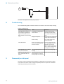
8 Troubleshooting
The Troubleshooting table indicates measures to be taken if the sensor stops working.
Table 4: Troubleshooting
LED indicator/fault pattern Cause Measures
Yellow LED does not light up
e
ven though the light beam is
aligned to the object and the
object is within the set sensing
range
No voltage or voltage below
the limit values
Check the power supply,
check all electrical connec‐
tions (cables and plug connec‐
tions)
Voltage interruptions Ensure there is a stable power
suppl
y without interruptions
Sensor is faulty If the power supply is OK,
replace the sensor
Yellow LED flashes Sensor is still ready for opera‐
tion, but the operating condi‐
tions are not ideal
Check the operating condi‐
tions: Fully align the beam of
light (light spot) with the
object / Clean the optical sur‐
faces / Check sensing range
and adjust if necessary
Yellow LED lights up, no object
in t
he path of the beam
The sensing range distance is
too large
Reduce the sensing range
Object is in the path of the
beam, yellow LED does not
light up
Distance between the sensor
and the object is too long or
sensing range is set too short
Reduce the sensing range
9 Disassembly and disposal
The sensor must be disposed of according to the applicable country-specific regula‐
t
ions. Efforts should be made during the disposal process to recycle the constituent
materials (particularly precious metals).
8 T
ROUBLESHOOTING
10
8025391 / 24.06.2020 | SICK
Subject to change without notice

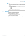
NOTE
Dis
posal of batteries, electric and electronic devices
•
According to international directives, batteries, accumulators and electrical or
electronic devices must not be disposed of in general waste.
•
The owner is obliged by law to return this devices at the end of their life to the
respective public collection points.
•
WEEE:
This symbol on the product, its package or in this document, indi‐
c
ates that a product is subject to these regulations.
10 Maintenance
SICK sensors are maintenance-free.
W
e recommend doing the following regularly:
•
Clean the external lens surfaces
•
Check the screw connections and plug-in connections
No modifications may be made to devices.
Subject to change without notice. Specified product properties and technical data are
not written guarantees.
MAINTENANCE 10
8025391 / 24.06.2020 | SICK
Subject to change without notice
11

11 Technical specifications
Laser class 1
Sensing range 30 ... 400 mm
Sensing range max. 10 ... 400 mm
1)
Light spot diameter/distance 0.4 mm / 150 mm
Supply voltage U
B
DC 10 ... 30 V
2)
Output current I
ma
x.
30 mA
Switching frequency 1,000 Hz
3)
Max. response time 0.625 ms
4)
Enclosure rating IP67
Protection class II
5)
Circuit protection A, B, C
6)
Ambient operating temperature -20 ... +50 °C
1)
Object with 90 % remission (based on standard white DIN 5033)
2)
Limit values. U
B
c
onnections reverse-polarity protected. Residual ripple max 5 V
PP
3)
With light / dark ratio 1:1
4)
Signal transit time with resistive load
5)
Reference voltage DC 50 V
6)
A = U
B
-c
onnections reverse polarity protected
B = inputs and output reverse-polarity protected
C = Interference suppression
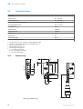
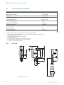
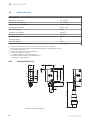
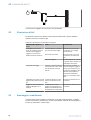
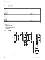
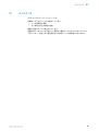
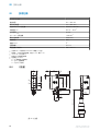
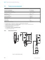
11.1 Dimensional drawing
10.2 (0.4)
6.9 (0.27)
0.5
(0.02)
21
(0.83)
0.5
(0.02)
9.7
(0.38)
3
(0.12)
11.5
(0.45)
31.5 (1.24)
28.5 (1.12)
25.4 (1.00)
2.3
(0.09)
18.3
(0.72)
305 (12.01)
9.7
(0.38)
12
(0.47)
1
2
4
4
3
Figure 3: Dimensional drawing
11 T
ECHNICAL SPECIFICATIONS
12
8025391 / 24.06.2020 | SICK
Subject to change without notice

1
Center of optical axis, sender
2
Center of optical axis, receiver
3
Operating and status indicators
4
M3 threaded mounting hole
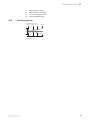
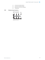
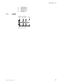
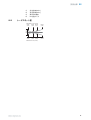
11.2 Light spot diagram
Sensor
Ø 0.4
(0.02)
Ø 2.2
(0.09)
Ø 1.8
(0.07)
Ø 4.6
(0.18)
Distance in mm (inch)
Diameter in mm (inch)
25
(0.98)
150
(5.91)
250
(9.84)
400
(15.75)
TECHNICAL SPECIFICATIONS 11
8025391 / 24.06.2020 | SICK
Subject to change without notice
13
Page is loading ...
Page is loading ...
Page is loading ...
Page is loading ...
Page is loading ...
Page is loading ...
Page is loading ...
Page is loading ...
Page is loading ...
Page is loading ...
Page is loading ...
Page is loading ...
Page is loading ...
Page is loading ...
Page is loading ...
Page is loading ...
Page is loading ...
Page is loading ...
Page is loading ...
Page is loading ...
Page is loading ...
Page is loading ...
Page is loading ...

1
Centre de l’axe optique émetteur
2
Centre de l’axe optique récepteur
3
Éléments de commande et d'affichage
4
Taraudage M3
33.2 Schéma du spot lumineux
Sensor
Ø 0.4
(0.02)
Ø 2.2
(0.09)
Ø 1.8
(0.07)
Ø 4.6
(0.18)
Distance in mm (inch)
Diameter in mm (inch)
25
(0.98)
150
(5.91)
250
(9.84)
400
(15.75)
CARACTÉRISTIQUES TECHNIQUES 33
8025391 / 24.06.2020 | SICK
Subject to change without notice
37

Page is loading ...
Page is loading ...
Page is loading ...
Page is loading ...
Page is loading ...
Page is loading ...
Page is loading ...
Page is loading ...
Page is loading ...
Page is loading ...

1
Centro do eixo do sistema óptico, emissor
2
Centro do eixo do sistema óptico receptor
3
Elementos de comando e indicação
4
Rosca de fixação M3
44.2 Diagrama do ponto de luz
Sensor
Ø 0.4
(0.02)
Ø 2.2
(0.09)
Ø 1.8
(0.07)
Ø 4.6
(0.18)
Distance in mm (inch)
Diameter in mm (inch)
25
(0.98)
150
(5.91)
250
(9.84)
400
(15.75)
DADOS TÉCNICOS 44
8025391 / 24.06.2020 | SICK
Subject to change without notice
49
Page is loading ...
Page is loading ...
Page is loading ...
Page is loading ...
Page is loading ...
Page is loading ...
Page is loading ...
Page is loading ...
Page is loading ...
Page is loading ...
Page is loading ...
Page is loading ...
Page is loading ...
Page is loading ...
Page is loading ...
Page is loading ...
Page is loading ...
Page is loading ...
Page is loading ...
Page is loading ...
Page is loading ...
Page is loading ...
Page is loading ...

1
Centro del eje óptico del emisor
2
Centro del eje óptico del receptor
3
Elementos de mando y visualización
4
Rosca de fijación M3
66.2 Diámetro del spot
Sensor
Ø 0.4
(0.02)
Ø 2.2
(0.09)
Ø 1.8
(0.07)
Ø 4.6
(0.18)
Distance in mm (inch)
Diameter in mm (inch)
25
(0.98)
150
(5.91)
250
(9.84)
400
(15.75)
DATOS TÉCNICOS 66
8025391 / 24.06.2020 | SICK
Subject to change without notice
73
Page is loading ...
Page is loading ...
Page is loading ...
Page is loading ...
Page is loading ...
Page is loading ...
Page is loading ...
Page is loading ...
Page is loading ...
Page is loading ...
Page is loading ...

1
发射器光轴中心
2
接收器光轴中心
3
操作及显示元件
4
紧固螺纹 M3
77.2 光点图
Sensor
Ø 0.4
(0.02)
Ø 2.2
(0.09)
Ø 1.8
(0.07)
Ø 4.6
(0.18)
Distance in mm (inch)
Diameter in mm (inch)
25
(0.98)
150
(5.91)
250
(9.84)
400
(15.75)
技术参数 77
8025391 / 24.06.2020 | SICK
Subject to change without notice
85
Page is loading ...
Page is loading ...
Page is loading ...
Page is loading ...
Page is loading ...
Page is loading ...
Page is loading ...
Page is loading ...
Page is loading ...
Page is loading ...
Page is loading ...

1
投光器光軸の中心
2
受光器光軸の中心
3
操作/表示要素
4
M3 固定ネジ穴
88.2 レーザスポット図
Sensor
Ø 0.4
(0.02)
Ø 2.2
(0.09)
Ø 1.8
(0.07)
Ø 4.6
(0.18)
Distance in mm (inch)
Diameter in mm (inch)
25
(0.98)
150
(5.91)
250
(9.84)
400
(15.75)
技術仕様 88
8025391 / 24.06.2020 | SICK
Subject to change without notice
97
Page is loading ...
Page is loading ...
Page is loading ...
Page is loading ...
Page is loading ...
Page is loading ...
Page is loading ...
Page is loading ...
Page is loading ...
Page is loading ...
Page is loading ...

1
Середина оптической оси передатчика
2
Середина оптической оси приемника
3
Элементы управления и индикаторы
4
Резьбовое крепежное отверстие М3
99.2 Схема светового пятна
Sensor
Ø 0.4
(0.02)
Ø 2.2
(0.09)
Ø 1.8
(0.07)
Ø 4.6
(0.18)
Distance in mm (inch)
Diameter in mm (inch)
25
(0.98)
150
(5.91)
250
(9.84)
400
(15.75)
Detailed addresses and further locations at www.sick.com
Australia
Phone +61 (3) 9457 0600
1800 33 48 02 – tollfree
E-Mail [email protected]
Austria
Phone +43 (0) 2236 62288-0
E-Mail of[email protected]
Belgium/Luxembourg
Phone +32 (0) 2 466 55 66
E-Mail [email protected]
Brazil
Phone +55 11 3215-4900
E-Mail [email protected]
Canada
Phone +1 905.771.1444
E-Mail [email protected]
Czech Republic
Phone +420 234 719 500
E-Mail [email protected]
Chile
Phone +56 (2) 2274 7430
E-Mail [email protected]
China
Phone +86 20 2882 3600
E-Mail info.c[email protected]
Denmark
Phone +45 45 82 64 00
E-Mail [email protected]
Finland
Phone +358-9-25 15 800
E-Mail [email protected]
France
Phone +33 1 64 62 35 00
E-Mail [email protected]
Germany
Phone +49 (0) 2 11 53 010
E-Mail [email protected]
Greece
Phone +30 210 6825100
E-Mail [email protected]
Hong Kong
Phone +852 2153 6300
E-Mail [email protected]
Hungary
Phone +36 1 371 2680
E-Mail ertekesit[email protected]
India
Phone +91-22-6119 8900
E-Mail info@sick-india.com
Israel
Phone +972 97110 11
E-Mail [email protected]
Italy
Phone +39 02 27 43 41
E-Mail [email protected]
Japan
Phone +81 3 5309 2112
E-Mail suppor[email protected]
Malaysia
Phone +603-8080 7425
E-Mail enquiry.m[email protected]
Mexico
Phone +52 (472) 748 9451
E-Mail [email protected]
Netherlands
Phone +31 (0) 30 229 25 44
E-Mail [email protected]
New Zealand
Phone +64 9 415 0459
0800 222 278 – tollfree
E-Mail [email protected]
Norway
Phone +47 67 81 50 00
E-Mail [email protected]
Poland
Phone +48 22 539 41 00
E-Mail [email protected]
Romania
Phone +40 356-17 11 20
E-Mail [email protected]
Russia
Phone +7 495 283 09 90
E-Mail [email protected]
Singapore
Phone +65 6744 3732
E-Mail [email protected]
Slovakia
Phone +421 482 901 201
E-Mail [email protected]
Slovenia
Phone +386 591 78849
E-Mail of[email protected]
South Africa
Phone +27 10 060 0550
E-Mail info@sickautomation.co.za
South Korea
Phone +82 2 786 6321/4
E-Mail infokor[email protected]
Spain
Phone +34 93 480 31 00
E-Mail [email protected]
Sweden
Phone +46 10 110 10 00
E-Mail [email protected]
Switzerland
Phone +41 41 619 29 39
E-Mail [email protected]
Taiwan
Phone +886-2-2375-6288
E-Mail [email protected]
Thailand
Phone +66 2 645 0009
E-Mail [email protected]
Turkey
Phone +90 (216) 528 50 00
E-Mail [email protected]
United Arab Emirates
Phone +971 (0) 4 88 65 878
E-Mail [email protected]
United Kingdom
Phone +44 (0)17278 31121
E-Mail [email protected]
USA
Phone +1 800.325.7425
E-Mail [email protected]
Vietnam
Phone +65 6744 3732
E-Mail sales.g[email protected]
ТЕХНИЧЕСКИЕ ХАРАКТЕРИСТИКИ 99
8025391 / 24.06.2020 | SICK
Subject to change without notice
109
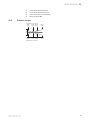
-
 1
1
-
 2
2
-
 3
3
-
 4
4
-
 5
5
-
 6
6
-
 7
7
-
 8
8
-
 9
9
-
 10
10
-
 11
11
-
 12
12
-
 13
13
-
 14
14
-
 15
15
-
 16
16
-
 17
17
-
 18
18
-
 19
19
-
 20
20
-
 21
21
-
 22
22
-
 23
23
-
 24
24
-
 25
25
-
 26
26
-
 27
27
-
 28
28
-
 29
29
-
 30
30
-
 31
31
-
 32
32
-
 33
33
-
 34
34
-
 35
35
-
 36
36
-
 37
37
-
 38
38
-
 39
39
-
 40
40
-
 41
41
-
 42
42
-
 43
43
-
 44
44
-
 45
45
-
 46
46
-
 47
47
-
 48
48
-
 49
49
-
 50
50
-
 51
51
-
 52
52
-
 53
53
-
 54
54
-
 55
55
-
 56
56
-
 57
57
-
 58
58
-
 59
59
-
 60
60
-
 61
61
-
 62
62
-
 63
63
-
 64
64
-
 65
65
-
 66
66
-
 67
67
-
 68
68
-
 69
69
-
 70
70
-
 71
71
-
 72
72
-
 73
73
-
 74
74
-
 75
75
-
 76
76
-
 77
77
-
 78
78
-
 79
79
-
 80
80
-
 81
81
-
 82
82
-
 83
83
-
 84
84
-
 85
85
-
 86
86
-
 87
87
-
 88
88
-
 89
89
-
 90
90
-
 91
91
-
 92
92
-
 93
93
-
 94
94
-
 95
95
-
 96
96
-
 97
97
-
 98
98
-
 99
99
-
 100
100
-
 101
101
-
 102
102
-
 103
103
-
 104
104
-
 105
105
-
 106
106
-
 107
107
-
 108
108
-
 109
109


Ask a question and I''ll find the answer in the document
Finding information in a document is now easier with AI
in other languages
- italiano: SICK GTB6L Istruzioni per l'uso
- français: SICK GTB6L Mode d'emploi
- español: SICK GTB6L Instrucciones de operación
- Deutsch: SICK GTB6L Bedienungsanleitung
- русский: SICK GTB6L Инструкция по эксплуатации
- português: SICK GTB6L Instruções de operação
- 日本語: SICK GTB6L 取扱説明書
Related papers
-
SICK GTE6L Operating instructions
-
-
-
-
SICK GSE6L Operating instructions
-
-
-
-
SICK WT100-2 energetic Operating instructions
-