Page is loading ...

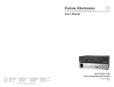
User’s Guide
Direct Digital Transmitter/Direct Digital Receiver
68-545-01 A
Printed in the USA
11 01
DDTX/DDRX DVI
DDTX/DDRX DVI • Installation
Description and Installation
2
Description
The Direct Digital Transmitter (DDTX) half of the DDTX/DDRX
DVI pair accepts a Digital Visual Interface (DVI) signal or a
Digital Flat Panel (DFP) signal (with a DFP-to-DVI adapter) from
any device that outputs digital video. The DDTX creates
proprietary digital signals, and outputs the signals over coaxial
cable to the Direct Digital Receiver (DDRX) half of the pair. The
transmitter also sends and receives the bidirectional Display Data
Channel (DDC) signals on a separate set of connectors. The
receiver converts the digital and DDC signals back to DVI video,
and outputs it for use by a compatible display device. The
maximum separation between the DDTX and DDRX depends on
the cables used:
• Maximum 150’ (45.72 meters) — This limit applies to systems
using cable of the quality of Extron High Resolution cable.
• Maximum 330’ (100.58 meters) — This limit applies to systems
using cable of the quality of Extron Super High Resolution
cable.
The DDTX is rack mountable and has an internal switching
power supply.
The DDRX comes with its own external desktop power supply
and a detachable bracket for mounting the unit to a projector
mount or other convenient surface. The DDRX is also through-
or under-desk mountable with optional mounting kits.
Installation
1. Power off the computer and its local monitor.
2. For optional rack mounting, mount the DDTX on one side
of a 19" 1U Universal Rack Shelf (Extron part #60-190-01)
(figure 1).
False front panel
uses 2 front holes only
4-40 X 1/8 screws
Use 2 mounting holes
on opposite corners
D
D
T
X
D
V
I
D
I
R
E
C
T
D
I
G
I
T
A
L
T
R
A
N
S
M
I
T
T
E
R
Figure 1 — Rack mounting a DDTX

DDTX/DDRX DVI • InstallationDDTX/DDRX DVI • Installation
Installation
43
a. If feet were previously installed on the bottom of the
case, remove them.
b. Mount the DDTX on the rack shelf, using two 4-40 x
1/8 screws in opposite (diagonal) corners to secure the
case to the shelf.
3. For optional bracket mounting, attach the included
mounting bracket to the DDRX using the 3 bracket screws.
The DDRX can then be attached to a projector mount or
some other secure surface by inserting the mounting screw
through the bracket’s slotted hole (figure 2).
Digital projector
DVI cable
DDRX DVI
Ceiling
Figure 2 — Bracket mounting a DDRX
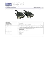
4. Connect the DDTX DVI input cable (figure 3) to the DVI
video output port of the computer (figure 4).
Transmitter
DVI Input Cable
Receiver
50/60 Hz
100-240 V 0.2A
TX0 TX1 TX2 TXC
DDC
OUTPUTS
ABCDE
TX0 TX1 TX2 TXC
DDC
DECBA
DISPLAY
INPUTS
DIRECT DIGITAL RECEIVER
DDRX DVI
9 -12V 1.0A
POWER
Figure 3 — DDTX and DDRX connector panels
5. Connect coax cable between the TX0, TX1, TX2, and TXC
BNC connectors on the rear of the DDTX and those on the
DDRX.
6. Connect a DDC cable between the DDC connectors on the
rear of the DDTX and those on the DDRX, see DDC Cable,
below.
7. Connect the desired DVI/DFP-compatible monitor, LCD
panel, or projector to the Display connector on the rear of
the DDRX.
DDTX DVI
DIRECT DIGITAL TRANSMITTER
DVI cable
or
Direct digital displays
4 BNC cable
Front panel
Rear panel
Rear panel
Comm-Link cable
DDTX DVI DDRX DVI
PC computer
digital video out
HDTV plasma Large screen display
DISPLAY
9 -12V 1.0A
POWER
TX0 TX1 TX2 TXC
DDC
DECBA
INPUTS
DIRECT DIGITAL RECEIVER
DDRX DVI
50/60 Hz
100-240 V 0.3A
TX0 TX1 TX2 TXC
DDC
OUTPUTS
ABCDE
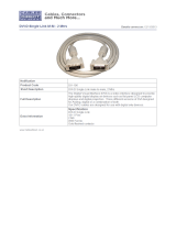
Figure 4 — DDTX/DDRX typical application
The maximum permissible length of the DVI input and
output cables is 16.4 feet (5 meters). Ensure that the
cables do not exceed the maximum permissible length,
otherwise images may be distorted or missing. Extron
does not guarantee signal integrity beyond 16.4 feet.
8. Connect a standard IEC power cord between the DDTX
power connector and a 100 to 240VAC, 50 Hz or 60 Hz
power source.
9. Connect 9-12VDC to the power connector on the DDRX,
either from the included external power supply or from a
source on the projector.
10. Power on the local monitor.
11. Power on the computer.
DDC Cable
The DDTX/DDRX DVI pair requires a DDC cable, up to 330’ in
length. Extron’s Custom Cables on Call can make a DDC cable
made-to-order, or it can be made on-site with Extron’s Plenum

DDTX/DDRX DVI • InstallationDDTX/DDRX DVI • Installation
Installation
43 DDTX/DDRX DVI • OperationDDTX/DDRX DVI • Installation and Operation 65
Paired Set
The DDTX and DDRX are a paired set, sharing a
common serial number. Each half is specifically tailored to
work with the other. Ensure that identically serial-
numbered halves are kept together and are not intermixed
with units from different sets. Units from different sets
are not guaranteed to work together.
When returning a DDTX or DDRX to Extron for service,
ensure that the identically serial-numbered paired half is
also returned.
DVI Connector Pin Assignments
Figure 7 and the table below define the pin assignments for the
DVI protocol.
18
916
17 24
Male connectorFemale connector
Figure 7 — DVI connectors
niP langiS niP langiS niP langiS
1-2ataDSDMT9 -1ataDSDMT71-0ataDSDMT
2+2ataDSDMT01+1ataDSDMT81+0ataDSDMT
3
4/2ataDSDMT
dleihS
11
3/1ataDSDMT
dleihS
91
5/0ataDSDMT
dleihS
4-4ataDSDMT21-3ataDSDMT02-5ataDSDMT
5+4ataDSDMT31+3ataDSDMT12+5ataDSDMT
6kcolCCDD41rewoPV5+22dleihSkcolCSDMT
7ataDCDD51)V5+(dnuorG32+kcolCSDMT
8noitcennoCoN61tceteDgulPtoH42-kcolCSDMT
Comm-Link cable and two 3.5 mm captive screw connectors.
Wire the connectors as shown in figure 5.
Stranded drain wire
Violet — DDC clock
White — DDC data
Black — hot plug detect
Red — logic 5V
Figure 5 — DDC Cable Connector
Indicator
Power LEDs — Located on the front panel (figure 6), these light
to indicate that the DDTX and DDRX are receiving power.
Transmitter
Receiver
DIRECT DIGITAL TRANSMITTER
DDTX DVI
TX0 TX1 TX2 TXC
DDC
DECBA
INPUTS
DIRECT DIGITAL RECEIVER
DDRX DVI
Power LED
Figure 6 — DDTX/DDRX front panels
Operation
After the transmitter, the receiver, and their connected devices are
powered up, the system is fully operational. If any problems are
encountered, ensure all cables are routed and connected properly.
Transmission distance is limited. The distance between
the transmitter and receiver can be up to 150’ if using
Extron High Resolution cable, or up to 330’ with Super
High Resolution cable.
Ensure that the computer and local monitor are properly
connected to the DDTX/DDRX pair, and that the DDTX,
the DDRX, and the monitor have power applied before
power is applied to the computer. If all other devices are
not turned on before the computer is powered on, the
image will not appear.

DDTX/DDRX DVI • InstallationDDTX/DDRX DVI • Installation
Installation
43 DDTX/DDRX DVI • Operation7
Operation
Extron Electronics, USA
1230 South Lewis Street, Anaheim, CA 92805
800.633.9876 714.491.1500 FAX 714.491.1517
USA
Extron Electronics, Europe
Beeldschermweg 6C, 3821 AH Amersfoort
+31.33.453.4040 FAX +31.33.453.4050
The Netherlands
Extron Electronics, Asia
135 Joo Seng Rd. #04-01, PM Industrial Bldg.
+65.383.4400 FAX +65.383.4664
Singapore 368363
Extron Electronics Information
ExtronWEB
™
: www.extron.com
ExtronFAX
™
: 714.491.0192
24-hour access—worldwide!
© 2001 Extron Electronics. All rights reserved.
FCC Class A Notice
Note: This equipment has been tested and found to comply with the limits for a
Class A digital device, pursuant to part 15 of the FCC Rules. These limits are
designed to provide reasonable protection against harmful interference when the
equipment is operated in a commercial environment. This equipment generates, uses
and can radiate radio frequency energy and, if not installed and used in accordance
with the instruction manual, may cause harmful interference to radio
communications. Operation of this equipment in a residential area is likely to cause
harmful interference, in which case the user will be required to correct the interference
at his own expense.
Note: This unit was tested with shielded cables on the peripheral devices. Shielded
cables must be used with the unit to ensure compliance.
Troubleshooting
DVI/DFP signals run at a very high frequency and are especially
susceptible to bad video connections, too many adapters, or too
long cables. To avoid the loss of an image or image jitter, follow
these guidelines:
• Do not exceed 16.4 feet (5 meters) on the output of the DDRX.
• Use only cable designed for DVI signals.
• Limit or avoid the use of adapters.
• Use only approved DVI/DFP connectors.
Specifications
Video input (DDTX)
Number and connectors ............. 1 attached cable with DVI male connector
Minimum input voltage ............. 0.30V p-p
Video throughput (DDTX and DDRX)
Connectors .................................... 4 BNC female connectors
1 female 3.5 mm 5-pole captive screw
connector (DDC channel)
Maximum bit rate ........................ 1.6 gigabits/second/color
Video signal characteristics (DDTX and DDRX)
Rise/fall time................................ 220 pS nominal, maximum 350 pS
Video output (DDRX)
Number and connectors ............. 1 DVI female
Maximum output cable length .. 16.4 feet (5 meters)
Minimum output voltage ........... 0.60V p-p
General
Power ............................................ DDTX ...... 100VAC to 240VAC, 50/60 Hz,
12 watts, internal, auto-
switchable
DDRX ...... 100VAC to 240VAC, 50/60 Hz,
7 watts, external, auto-
switchable
Temperature/humidity .............. Storage -40° to +158°F (-40° to +70°C) /
10% to 90%, non-condensing
Operating +32° to +122°F (0° to +50°C) /
10% to 90%, non-condensing
Mounting options DDTX ...... Rack mountable with optional
rack shelf, part #60-190-01
DDRX...... Bracket mountable with
included mounting bracket
Under/thru-desk mountable
with optional kit, part
#70-077-01 or 70-077-02
Enclosure type .............................. Two metal enclosures
Enclosure dimensions ................. DDTX 1.75" H x 8.75" W x 9.4" D
4.5 cm H x 22.2 cm W x 23.9 cm D
(depth excludes connectors)
DDRX 1.3" H x 5.7" W x 4.5" D
3.3 cm H x 14.5 cm W x 11.4 cm D
(depth excludes connectors)
Product weight ............................. 3.6 lbs (1.6 kg)
Shipping weight (pair) ............... 8 lbs (3.6 kg) total
Vibration ....................................... ISTA 1A in carton (International/National
Safe Transit Association)
Listings .......................................... UL, CUL
Compliances ................................. CE, FCC Class A
MTBF ............................................. 30,000 hours
Warranty ....................................... 3 years parts and labor
Specifications are subject to change without notice.
Optional Cables, Adapters, and Connectors
• 26-497-01 DVI (male) to DFP (female) adapter
• 26-498-01 DVI (female) to DFP (male) adapter
• 26-210-xx SuperFlex BNC-4 Mini HR Cable, up to 150‘
• 26-368-xx SuperFlex SHR 4 Super High Resolution Cable, up to 330’
• 26-378-xx Plenum BNC-5 Cable, up to 150’
• 26-461-xx Plenum Comm-Link Cable, up to 150’
• 10-319-10 3.5 mm captive screw connector
/