
Title:
2011-06-29
Sep. PL anoth.No.
Sep. PL same No. Without separ.PL
0
FG
Revision:
No. sheets:
PSSA-P
EN
Based on: / Replaces: Scale: Doc. type: Format:
NTS DOC A4
Responsible Department:
PSSA-P
UPS Operations and Maintenance Manuals
Take over Department:
ADDC
Language:
0 63
Supplier: Sheet No.:
N 4 2 1 8 R A 8 4 0 0 M 3 2 4 6 0
0 First issue
FG ACh 2011-06-29
DESCRIPTION DRAWN CHECKED DATE
REV.

Primary Switch Mode Inverter
UNV-F
OPERATION MANUAL
BHB.UNV-F.D65-1050.HB001

Primary Switch Mode Inverter
UNV-F
Operation Manual
Page 2 (28)
BHB.UNV-F.D65-1050.HB101
Notes to this manual
ATTENTION! Please read this manual very carefully before in-
stalling and commissioning the inverter.
This manual is part of the delivered device. Knowledge of this
document is obligatory for deals with the specified unit or
puts into operation. All works on the module such as trans-
port, putting into operation, adjustment and maintenance is
to be carried out by qualified personnel only. The rules for
prevention of accidents of the specific country and the uni-
versal safety rules acc. IEC 364 are to be observed!
This manual is equivalent to the technical revision of the in-
verter to the day of its printing. The contents are for infor-
mation purpose only and it is not included in the contract.
Technical changes between this manual and the actual prod-
uct are possible due to technical progress. The producer is
not responsible for uncorrect technical descriptions or data
inside this manual because there is no obligation to a perma-
nent actualization of this documentation.
The switch mode inverter will be manufactured according to
valid DIN- and VDE-standards such as VDE 0106 (part 100)
and VDE 0100 (part 410). The CE-label on the modules con-
firms the compliance with EU-standards for 73/23 EWG low
voltage and 89/339 EWG electromagnetical compatibility if
the installation and operation rules are observed.
All systems and components are delivered according to the
delivery conditions for electrical products and services of e-
lectronic industry and our own sales conditions. Changes of
contents in this manual such as technical data, dimensions,
weight and handling are possible.
In case of reclamation of delivered products please contact
us immediatily after receiving with delivery note number, de-
vice type, device number and fault description.
In case of visible changes on the device caused by the
customer (missing screws, new weldings, unmounted boards
a.s.o.) the customer looses the warranty. At operation under
non-specified conditions (acc. technical specifications), the
customer looses the warranty and there is no liability by the
producer. The responsibility for measurements to prevent ac-
cidents and material damages has the system operator (cus-
tomer), not the producer.

Primary Switch Mode Inverter
UNV-F
Operation Manual
Page 3 (28)
BHB.UNV-F.D65-1050.HB101
Contents
1.General Information..................................................
4
2.Type range...............................................................
6
3.Storage .................................................................... 6
4.Commissioning.........................................................
7
5.Handling................................................................... 9
6.Functions ...............................................................
11
6.1Schematic block diagram ....................................... 11
6.2Functional description............................................ 12
6.2.1 Safe electrical decoupling................................ 12
6.2.2 Input ...........................................................
13
6.2.3 Output ......................................................... 13
6.2.4 Dynamic regulation of output voltage ............... 13
6.2.5 RFI-Suppression ............................................ 13
6.3 Monitoring ......................................................... 13
6.3.1 Input voltage monitoring ................................ 13
6.3.2 Output voltage monitoring ...............................
14
6.3.3 Monitoring of Overheating............................... 14
6.3.4 Signals......................................................... 14
6.3.5 Adjustment of output parameters and monitoring
thresholds................................................... 14
6.3.6 CAN-Interface ............................................... 20
7.Operation in parallel ..............................................
20
8.Connectors............................................................. 21
8.1 Connector F-type................................................. 22
8.2 Connector - CAN-Bus ........................................... 21
9.Maintenance...........................................................
23
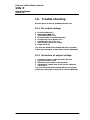
10.Trouble shooting.................................................. 24
10.1No output voltage ...............................................
24
10.2Distortion of output voltage.................................. 24
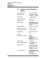
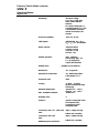
11.Technical specifications UNV-F.......................... 25
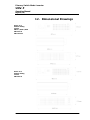
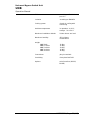
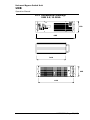
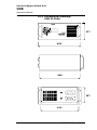
12. Dimensional drawings......................................... 25

Primary Switch Mode Inverter
UNV-F
Operation Manual
Page 4 (28)
BHB.UNV-F.D65-1050.HB101
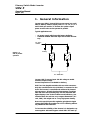
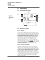
1. General Information
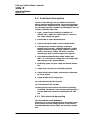
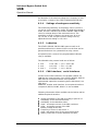
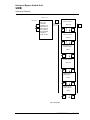
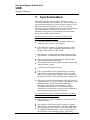
Inverter type UNV-F (named UNV on next pages) are avail-
able for delivery with an output power of 1.2, 1.8, 2.5, 3.3
and 5.0kVA per module. To increase the system output
power several units can be operated in parallel.
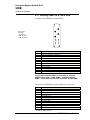
Typical applications are:
- AC power supply with input side battery buffering
- Industrial modular UPS with input side rectifier and bat-
tery
Battery
AC distribution
UNV
UNV
DC-Input
rectifier
Inverter UNV-F converts input side DC voltage to stable
sinewave output voltage.
Several frequencies are available for delivery
UNV-F are hot-plugable modules with rear side connectors.
Only the communication wire (CAN bus) is connected on the
front. The inverter is controlled and monitored by internal
microprocessor. All main functional parameters are adjust-
able with front side operating keys and are indicated with
digital displays. Due to the excellent overall efficiency (see
technical data) the unit has very compact dimensions (19-
rack, 3HU), low weight and so a very high power density.
Due to the special input side regulation principle the ripple
voltage limit fulfils the standard of CCITT-A-filtering without
any additional filter elements.
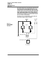
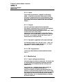
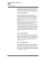
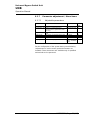
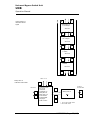
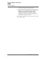
To increase the reliability of the inverter it is designed to op-
erate together with static bypass switch UNB. The static by-
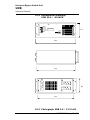
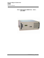
Picture 1.1:
UNV in parallel
operation

Primary Switch Mode Inverter
UNV-F
Operation Manual
Page 5 (28)
BHB.UNV-F.D65-1050.HB101
pass switch monitores the connected bypass mains and syn-
chronises the inverter output with mains frequency. In in-
verter preselection mode the UNB transfers the load supply
to bypass mains in case of inverter faults, high overload, bat-
tery low voltage. The transfer is nearly without voltage inter-
ruption. After problem solving the unit switches back to in-
verter operation automatically. In case of mains preselection
mode the inverter will take over the load if mains is not pre-
sent, out of limits or badly distorted.
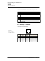
The primary source is programmable on static switch unit.
For the UNB a separate manual is available.
Battery
AC distribution
UNV
UNV
DC-Input
rectifier
UNB
BS
AC-Input
Mains
Manual bypass switch
Static bypass switch
Inverter
Picture 1.2:
Inverter operation
with static bypass
switch UNB

Primary Switch Mode Inverter
UNV-F
Operation Manual
Page 6 (28)
BHB.UNV-F.D65-1050.HB101
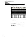
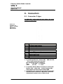
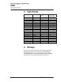
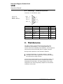
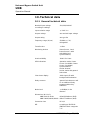
2. Type Range
Type
designation
UNV..
Item-
number
Input-
voltage
in V DC
Output-
voltage
in V AC
Output-
power
in VA
(bei cos =0.8)
Dimensions
W/H/D in mm
48-1.2F C65-1051 48/60 230 1200 483/133/360
48-1.8F C65-1052 48/60 230 1800 483/133/360
48-2.5F C65-1053 48/60 230 2500 483/133/360
48-3.3F C65-1054 48/60 230 3300 483/133/360
48-5.0F C65-1055 48/60 230 5000 483/133/440
108-1.2F C65-1061 108 230 1200 483/133/360
108-1.8F C65-1062 108 230 1800 483/133/360
108-2.5F C65-1063 108 230 2500 483/133/360
108-3.3F C65-1064 108 230 3300 483/133/360
108-5.0F C65-1065 108 230 5000 483/133/440
Available options and accessory parts
Additional connector
19-sliding bar
connector fastening
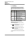
3. Storage
The modules have to be stored in a dry, dustfree room with
the specified storage temperature (observe technical specifi-
cations; chapter 11).

Primary Switch Mode Inverter
UNV-F
Operation Manual
Page 7 (28)
BHB.UNV-F.D65-1050.HB101
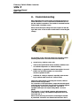
4. Commissioning
After unpacking the module search for damage based on ex-
ternal influences. In case of mechanical deformation do not
put the module in operation. The module is mounted into the
subrack with 4 frontside screws.
Please check the input voltage level and compare it with the
type lable value on the inverter module before connecting DC
voltage.
For mounting of the units and putting into operation onsite.
Following instructions and rules have to be observed:
mount in dry, dustfree rooms only
observe the specifications about ambient conditions such
as ambient temperature or relative humidity
highly dusty or aggressive chemical atmosphere is not al-
lowed; dew and dust together can cause short
circuits on printed circuits
sufficient air cooling is required, especially when mount-
ing in cabinets with several 19 subrack levels
Check DC voltage before connecting the inverter (observe
nominal values on type label).
For connection of DC input and AC output the backside panel
connector have to be used. The DC input is protected against
wrong polarity (unit does not switch on). The UNV is
equipped with input and output fusing (MCB`s on front
panel).
The inverters (1.2 to 5.0kVA) operates with temperature
controlled fan cooling. The ambient temperature has to be
lower than 40 °C.
Please check the load power before connecting the module.
A permanent overload is not allowed and decreases the in-

Primary Switch Mode Inverter
UNV-F
Operation Manual
Page 8 (28)
BHB.UNV-F.D65-1050.HB101
verters lifetime. Especially the inrush currents of loads have
to be observed ( for instance, a usual computer monitor can
have an inrush current of more than 50A! ).
The connection of the non-fused earthed conductor is re-
quired. The electrical connections have to be carried out acc.
pin list in chapter 8. Please use wires acc. VDE 0100 or equal
standard. To decrease voltage losses on cables usage of big-
ger sizes of wire as specified is recommended. For instance,
a high voltage loss on battery wires can decrease the backup
time.
Following installation rules should be observed:
single inverter:
check system wiring ( polarity of DC- supply line )
check that inverter is switched off
connect DC input with open DC bushbar fuses
connect AC loads
close DC bushbar fuses
switch on the unit with front side MCB
switch on load
inverters in parallel:
check system wiring ( polarity of DC- supply line, syn-
chron bus)
check if inverters are switched off
connect DC input with open DC bushbar fuses
check wiring between inverters (synchronization wires)
connect AC loads
close DC busbar fuses
switch on the units with front side MCBs
switch on load

Primary Switch Mode Inverter
UNV-F
Operation Manual
Page 9 (28)
BHB.UNV-F.D65-1050.HB101
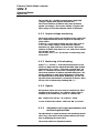
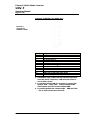
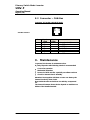
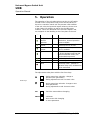
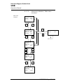
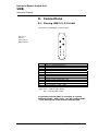
5. Handling
All operating elements are located on the front of the mod-
ule. The input and output side MCB are used as ON/OFF-
switch. The LEDs indicate the operation state of inverter. All
signals and monitorings will be described in the next chap-
ters.
LED Color Meaning
OPERATION green Inverter is switched on and operates
Uo green Inverter output voltage o.k.
(see pt. 6.3.5)
Ui>
red Input voltage high; input voltage >
Adjusted monitoring threshold; inverter
switches off(see pt. 6.3.5)
Ui<
red Input voltage low; input voltage <
Adjusted monitoring threshold; inverter
switches off(see pt. 6.3.5)
Io>
red Output current to high; short circuit or
overload on output
T>
red lights Continously: overheating of in-
verter by overload
light Blinks: poor cooling;
Inverter switches off delayed
ALARM
red Collective failure, delay time of relay
alarm adjustable, relay contact on X1;
all single errors included
Adjustment of the standard values and thresholds
The adjustment takes place with the two up / down keys,
which have following functions:
- during menu item selection: change to previ-
ous item (parameter)
- during adjustment mode: increase value
- during menu item selection: change to next
item (parameter)
- during adjustment mode: increase value
For switching between the menues please press both buttons
for 3 sec.

Primary Switch Mode Inverter
UNV-F
Operation Manual
Page 10 (28)
BHB.UNV-F.D65-1050.HB101
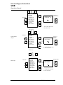
inverters in parallel
One unit operates as master and synchronizes all other units.
ATTENTION! The unit which transmits the synchonization
signal to synchronization bus at first will be the master. If
this master unit is disturbed or switched off, another unit
overtakes the master function. In systems with static bypass
switch (SBS) the inverters will be synchronized by SBS unit.
Picture 5.1:
Front view UNV-F

Primary Switch Mode Inverter
UNV-F
Operation Manual
Page 11 (28)
BHB.UNV-F.D65-1050.HB101
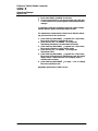
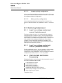
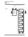
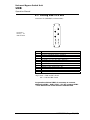
6. Functions
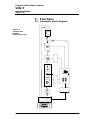
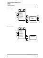
6.1 Schematic block diagram
Picture 6.1:
Schematic Block
Diagramm
Inverter UNV (F type)

Primary Switch Mode Inverter
UNV-F
Operation Manual
Page 12 (28)
BHB.UNV-F.D65-1050.HB101
6.2 Functional description
Inverters of the UNV-type are new switch mode inverters
with an innovate operation principle. The inverter transforms
the input side DC voltage into an AC voltage with high stabil-
ity concerning frequency, amplitude and waveshape. The unit
consists of following main parts:
1. Input / output connector HAN K 4/8 (UNV48-1.2F
UNV108-5.0F) / HAN K 6/6 (UNV48-5.0F) to connect in-
put, output voltage and signals
2. Passive filter to reduce RF interferences
3. Input circuit breaker (MCB) ; used as ON/OFF switch
4. Innovate DC/DC-converter topology consisting of
MOSFET/IGBT-converter , isolation transformer, rectifier
bridge to produce a voltage of appr. 380V DC, capacitor
block to store the DC voltage. The DC/DC-converter
modulates the input current to suppress the input AC.
5. Pulse width modulated inverter bridge (20kHz) with
IGBT`s to convert the DC voltage into an AC voltage with
high frequency and a stable amplitude
6. Monitoring system for input, output and internal parame-
ters
7. Output relay (necessary for paralleling operation)
8. Output circuit breaker (MCB), mechanically coupled with
DC circuit breaker
9. Output AC filter for RFI suppression
10. Control board for DC/DC converter
11. Control board for AC converter
12. Microprocessor based control unit performs controlling,
monitoring, adjustments (value storage) and displaying of
inverters parameter and serial communication via CAN-
Bus
6.2.1 Safe electrical decoupling
The unit fulfills the standard EN60950.
Observance of air and creeping distances, the isolation trans-
former and the separate wiring guarantee a safe electrical
decoupling between primary (input) and secondary (output)
side.

Primary Switch Mode Inverter
UNV-F
Operation Manual
Page 13 (28)
BHB.UNV-F.D65-1050.HB101
6.2.2 Input
The DC input is protected by a magnetic circuit breaker
(MCB) except the inverter with output-power of 5kVA.
The input is equipped with inrush current limitation to limit
the inrush current to the level of nominal input current. The
input voltage and current is visible on the front side digital
displays.
6.2.3 Output
The unit is generally equipped with an output MCB.
The output is continuously short circuit proof and supplies a
short circuit current of 2 to 3xInom for 2,5 sec.
In case of short circuit the unit switch on every 15sec. again
to check if the short circuit is away.
The inverter can be overcharged for a short time without
switching off. The overload alarm is preset to 10% overload
for 30 sec. It is possible to increase the load to 130% of
nominal load for a short period only.
6.2.4 Dynamic regulation of output voltage
For load steps between 10% and 100% Inom / 100% and
10% Inom the dynamic voltage deviation is < 3 % and is
regulated in < 1,5 ms to static accuracy.
6.2.5 RFI-Suppression
Inverter type UNV fulfills the standards EN 55011/55022
class .
6.3 Monitoring
6.3.1 Input voltage monitoring
The input voltage is monitored continuously. The actual value
is compared with the programmed monitoring thresholds.
The thresholds can be adjusted with the front keys (see
chapter 6.3.5).
The red LED "Ui<" signalizes inverter input voltage low
(voltage is lower than adjusted threshold Ui<).
The inverter switches off with an adjustable delay time. It
switches on again if the input voltage is in the correct range.
The switch-on voltage is adjustable. The hysteresis and delay
time protects the unit from an oscillation of the automatic
switch off function, e.g. if a discharged battery is unloaded
by inverter switch off.

Primary Switch Mode Inverter
UNV-F
Operation Manual
Page 14 (28)
BHB.UNV-F.D65-1050.HB101
The red LED "Ui>" signalizes inverter input voltage high
(voltage is higher than adjusted threshold Ui>)
The inverter switches off without delay time (protection
against overvoltage). The inverter switches on again if the
input voltage is lower than adjusted switch off threshold.
6.3.2 Output voltage monitoring
The inverter output voltage is transmitted to the control unit
by a voltage transformer and is compared to internally ad-
justed values.
If there is a correct output voltage the green LED "Uo O.K."
is on. If the output voltage is lower than the adjusted
threshold (e.g. high overload or short circuit), the inverter
switches off with a delay time of 2.5 sec. After 15 sec follows
an automatic restart.
The red LED Error is on. The inverter is continuously short
circuit proof.
6.3.3 Monitoring of Overheating
Signal "T>" ( red LED ) ; if the internal temperature of the
inverter is higher than the adjusted threshold. High ambient
temperature, poor cooling , permanent overload (appr. 20-
25%) or a defective fan can cause overheating of the unit.
The inverter switches off with an adjustable delay time. The
inverter switches on again if the temperature is lower than
the adjusted switch on threshold. Additionally, the fan volt-
age and current characteristic is monitored to detect a defec-
tive fan. This is indicated by a blinking LED T>.
6.3.4 Signals
All operation modes and error-states are indicated by LEDs
situated on the front panel. The collective failure signal is
available by an isolated relay contact on connector X1.
Max. contact load: 60V DC / 1A, 110V DC / 0.45A.
In case of failure the contacts COM and NO are closed.
6.3.5 Adjustment of output parameters and
monitoring thresholds
The adjustment of output parameters and monitoring thresh-
olds is easy. The values can be adjusted with the two front-
keys by displaying the actual value.
The inverter offers two adjustment menus:

Primary Switch Mode Inverter
UNV-F
Operation Manual
Page 15 (28)
BHB.UNV-F.D65-1050.HB101
Basic menu PM1 is available for all users
Service menu PM2 is for service personnel only. PM2 has
a code protection to protect against unallowed parameter
changes.
In operation mode the top display shows the output voltage
and the bottom display shows the output current.
For adjustment of parameters in basic menu PM1 the follow-
ing procedure has to be carried out:
1. press both keys UP/DOWN(
) together for a short time;
the inverter changes to adjustment mode
2. press the key UP( ) or DOWN( ) to change the
adjustment parameter (see also table on bottom)
3. press both keys UP/DOWN( ) together for a short time;
the inverter changes to value change mode
4. press the key UP(
) or DOWN( ) to change the
adjustment value
5. press both keys UP/DOWN( ) together for a short time;
the inverter changes back to adjustment mode (the upper
display shows a horizontal line / the changed value is
stored at this moment)
6. press both keys UP/DOWN(
) for appr. 3 sec. to change
back into operation mode
Adjustable parameters in PM1 (see a)):

Primary Switch Mode Inverter
UNV-F
Operation Manual
Page 16 (28)
BHB.UNV-F.D65-1050.HB101
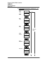
a) Standard display during operation / monitoring of in - / out-
put parameters:
Output-
voltage
Output-
current
Input-
voltage
Input-
current
Output-
frequency
device-
temperature
Restart and
selftest
Input-power

Primary Switch Mode Inverter
UNV-F
Operation Manual
Page 17 (28)
BHB.UNV-F.D65-1050.HB101
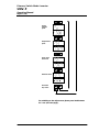
For switching to the adjust menu please press both buttons
for 3 sec (see next page).
Output-
Complex
p
ower
Output-Active
p
ower
Power factor
of the load
Hardware-Reset
Press both
keys short!

Primary Switch Mode Inverter
UNV-F
Operation Manual
Page 18 (28)
BHB.UNV-F.D65-1050.HB101
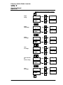
Adjust the values and Thresholds as follows
Output-
voltage
Output-
undervoltage
Output-
overvoltage
Input-
overvoltage
Input undervolta-
ge
(restart) voltage
Input-
overvoltage

Primary Switch Mode Inverter
UNV-F
Operation Manual
Page 19 (28)
BHB.UNV-F.D65-1050.HB101
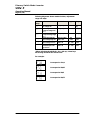
Following diagramm shows standard values, adjustment
range and steps:
Dis-
play1
notice Standard Range Step
nominal value of out-
put voltage Uo*
230 [V AC] 200...255 0,25
[V]
monitoring threshold
of output voltage low
Uo<*
207 [V AC] 180...230 1,0 [V]
Monitoring threshold
of output voltage high
Uo>*
253 [V AC] 230...270 1,0 [V]
switch off threshold
input voltage high Ui>
48V:75 [V DC]
108V: 130
0...80
0...135
0,1 [V]
0,25
switch off threshold
input voltage low Ui<
48V:41 [V DC]
108V: 92
41...80
90...110
0,1 [V]
0,25
switch on again
threshold input volt-
age low Ui<
48V:45 [V DC]
108V: 96
41...80
90...110
0,1 [V]
0,25
*When adjusting thresholds Uo, Uo> with up / down keys
the moving dot shows the actual value:
For example:
Corres
p
ond to 230
,
0
Corres
p
ond to 230
,
25
Corres
p
ond to 230
,
5
Corres
p
ond to 230
,
75
Page is loading ...
Page is loading ...
Page is loading ...
Page is loading ...
Page is loading ...
Page is loading ...
Page is loading ...
Page is loading ...
Page is loading ...
Page is loading ...
Page is loading ...
Page is loading ...
Page is loading ...
Page is loading ...
Page is loading ...
Page is loading ...
Page is loading ...
Page is loading ...
Page is loading ...
Page is loading ...
Page is loading ...
Page is loading ...
Page is loading ...
Page is loading ...
Page is loading ...
Page is loading ...
Page is loading ...
Page is loading ...
Page is loading ...
Page is loading ...
Page is loading ...
Page is loading ...
Page is loading ...
Page is loading ...
Page is loading ...
Page is loading ...
Page is loading ...
Page is loading ...
Page is loading ...
Page is loading ...
Page is loading ...
Page is loading ...
Page is loading ...
-
 1
1
-
 2
2
-
 3
3
-
 4
4
-
 5
5
-
 6
6
-
 7
7
-
 8
8
-
 9
9
-
 10
10
-
 11
11
-
 12
12
-
 13
13
-
 14
14
-
 15
15
-
 16
16
-
 17
17
-
 18
18
-
 19
19
-
 20
20
-
 21
21
-
 22
22
-
 23
23
-
 24
24
-
 25
25
-
 26
26
-
 27
27
-
 28
28
-
 29
29
-
 30
30
-
 31
31
-
 32
32
-
 33
33
-
 34
34
-
 35
35
-
 36
36
-
 37
37
-
 38
38
-
 39
39
-
 40
40
-
 41
41
-
 42
42
-
 43
43
-
 44
44
-
 45
45
-
 46
46
-
 47
47
-
 48
48
-
 49
49
-
 50
50
-
 51
51
-
 52
52
-
 53
53
-
 54
54
-
 55
55
-
 56
56
-
 57
57
-
 58
58
-
 59
59
-
 60
60
-
 61
61
-
 62
62
-
 63
63


Ask a question and I''ll find the answer in the document
Finding information in a document is now easier with AI
Related papers
Other documents
-
Votronic 3183 Installation guide
-
-
-
Telair TE 1500 SI-AC Inverter NVS Sinus User manual
-
Projecta Easy Install RF CH Specification
-
 MPP Solar PIP-MS Series Installation guide
-
-
Sencor SBS 2507 BL User manual
-
LogiLink MP0019 Datasheet
-
NewMar 48-1000RM Installation & Operation Manual
