FreeMotion FLY/REAR DELT F806.0 Owner's manual
- Type
- Owner's manual

OWNERʼS MANUAL
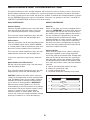
CAUTION
Read all precautions and instruc-
tions in this manual before using
this equipment. Keep this manual
for future reference.
QUESTIONS?
If you have questions, or if parts
are damaged or missing, please
see HOW TO CONTACT
CUSTOMER CARE on the back
cover of this manual.
www.freemotionfitness.com
Model No. F806.0
Serial No.
Write the serial number in the
space above for reference.
Serial Number Decal

2
TABLE OF CONTENTS
IMPORTANT PRECAUTIONS . . . . . . . . . . . . . . . . . . . . . . . . . . . . . . . . . . . . . . . . . . . . . . . . . . . . . . . . . . . . . . . .3
WARNING DECAL PLACEMENT . . . . . . . . . . . . . . . . . . . . . . . . . . . . . . . . . . . . . . . . . . . . . . . . . . . . . . . . . . . . . .4
BEFORE YOU BEGIN . . . . . . . . . . . . . . . . . . . . . . . . . . . . . . . . . . . . . . . . . . . . . . . . . . . . . . . . . . . . . . . . . . . . . .5
P
ART IDENTIFICATION CHART . . . . . . . . . . . . . . . . . . . . . . . . . . . . . . . . . . . . . . . . . . . . . . . . . . . . . . . . . . . . . .6
ASSEMBLY . . . . . . . . . . . . . . . . . . . . . . . . . . . . . . . . . . . . . . . . . . . . . . . . . . . . . . . . . . . . . . . . . . . . . . . . . . . . . . .7
ADJUSTMENT . . . . . . . . . . . . . . . . . . . . . . . . . . . . . . . . . . . . . . . . . . . . . . . . . . . . . . . . . . . . . . . . . . . . . . . . . . .19
MAINTENANCE AND TROUBLESHOOTING . . . . . . . . . . . . . . . . . . . . . . . . . . . . . . . . . . . . . . . . . . . . . . . . . . .21
CABLE DIAGRAM . . . . . . . . . . . . . . . . . . . . . . . . . . . . . . . . . . . . . . . . . . . . . . . . . . . . . . . . . . . . . . . . . . . . . . . . .23
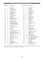
PART LIST . . . . . . . . . . . . . . . . . . . . . . . . . . . . . . . . . . . . . . . . . . . . . . . . . . . . . . . . . . . . . . . . . . . . . . . . . . . . . .25
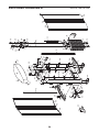
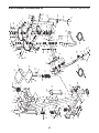
EXPLODED DRAWING . . . . . . . . . . . . . . . . . . . . . . . . . . . . . . . . . . . . . . . . . . . . . . . . . . . . . . . . . . . . . . . . . . . .26
HOW TO CONTACT CUSTOMER CARE . . . . . . . . . . . . . . . . . . . . . . . . . . . . . . . . . . . . . . . . . . . . . . .Back Cover
FREEMOTION is a registered trademark of ICON IP, Inc.

3
IMPORTANT PRECAUTIONS
1. Before beginning any exercise program,
consult your physician. This is especially
important for persons over age 35 or per-
sons with pre-existing health problems.
2. Use the strength equipment only as
described in this manual.
3. It is the responsibility of the owner to
ensure that there is enough space around
the strength equipment for the intended
exercise.
4. Use the strength equipment only on a level
surface. Cover the floor beneath the
strength equipment to protect the floor.
5. Anchor the strength equipment to the floor
with the anchor strap (see page 5) where
required or where possible to provide maxi-
mum stability.
6. It is the responsibility of the owner to
ensure that all users of the strength equip-
ment are adequately informed of all
precautions, have read and understood all
warning and caution labels, and are
informed of how to use the strength equip-
ment properly.
7. All users of the strength equipment should
be instructed to report any injury or
strength equipment irregularity to facility
staff immediately.
8. Keep children under age 12 and pets away
from the strength equipment at all times.
9. The strength equipment is designed to sup-
port a maximum user weight of 350 lbs.
(159 kg).
10. Always wear athletic shoes for foot protec-
tion while exercising.
11. Keep hands and feet away from moving
parts. Do not lean on or rest your hands on
the strength equipment while it is in use.
12. Make sure that the weight pin is completely
inserted into one of the weight plates.
13. Check each cable, each cable connection,
and each pulley before each use of the
strength equipment. Make sure that all parts
are properly tightened. Replace any worn
parts immediately.
14. Make sure that each cable remains on the
pulleys at all times. If a cable binds while
you are exercising, stop immediately and
make sure the cable is on the pulleys and
that nothing is interfering with the cable or
the pulleys.
15. Over exercising may result in serious injury
or death. If you feel faint or if you experi-
ence pain while exercising, stop
immediately and cool down.
WARNING: To reduce the risk of serious injury, read all important precautions and
instructions in this manual and all warnings on your strength equipment before using your strength
e
quipment. FreeMotion Fitness assumes no responsibility for personal injury or property damage
sustained by or through the use of this product.

4
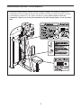
WARNING DECAL PLACEMENT
Refer to the drawings below to identify small parts used for assembly. The number in parentheses by
e
ach drawing is the key number of the part, from the PART LIST near the end of this manual. The num-
ber following the parentheses is the quantity needed for assembly. Note: If a part is not in the
hardware kit, check to see if it has been preattached. To avoid damaging parts, do not use power
tools.

Assembled Dimensions:
Height: 6 ft. 4 in. (193 cm)
Width: 5 ft. 7 in. (170 cm)
Depth: 4 ft. 5 in. (135 cm)
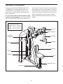
5
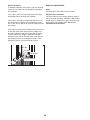
Anchor Strap
Weights
Backrest
Adjustment Lever
Adjustment Knob
Seat
Tower
Handlebar
Handgrip
Weight Pin
BEFORE YOU BEGIN
T
hank you for selecting the FREEMOTION
®
E
PIC™
FLY/REAR DELT strength equipment. With unre-
stricted motion, you can work your bodyʼs muscle
groups the way you do naturally, to train more effec-
t
ively and efficiently.
For your benefit, read this manual carefully before
using the strength equipment. If you have questions
after reading this manual, please see the back cover
o
f this manual. To help us assist you, note the product
model number and serial number before contacting us.
The model number and the location of the serial num-
ber decal are shown on the front cover of this manual.
Before reading further, please review the drawing
below and familiarize yourself with the parts that are
labeled.
Drop-down
Weight/Knob
Cam Arm

6
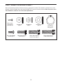
Refer to the drawings below to identify small parts required for assembly. The number in parentheses by each
drawing is the key number of the part, from the PART LIST near the end of this manual. Note: If a part is not in
the hardware kit, check to see if it has been preattached.
PART IDENTIFICATION CHART
M4 x 13mm
Self-tapping
Screw (27)–2
M8 Washer
(80)–7
M10 Washer
(31)–6
25mm Snap
Ring (39)–8
M10 x 35mm Socket
Patch Screw (76)–4
M8 x 25mm Socket
Screw (75)–7
M6 x 15mm Button
Screw (35)–4
M6 Washer
(34)–4
M10 x 30mm Socket
Patch Screw (30)–2

7
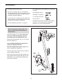
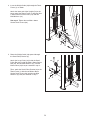
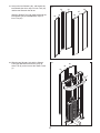
1
1.
Orient the Upright (72) as shown. Have a sec-
ond person hold the Upright to prevent it
from falling until you complete this step.
Remove the indicated parts (24, 31, 32, and 83)
from the Upright (72).
See the CABLE DIAGRAM on page 23 and
identify the Weight Cable (40).
Orient the Weight Cable (40) as shown, and
insert it through the Upright (72).
Set the Large Pulley (24) that you just removed
over the Weight Cable (40).
Attach the Large Pulley (24) to the Upright (72)
with the M10 x 65mm Socket Bolt (83), the two
M10 Washers (31), and the M10 Locknut (32)
that you just removed.
Before beginning assembly, make sure
that you understand the information in
the box above.
24
72
31
32
31
83
40
ASSEMBLY
• Assembly requires two persons.
•
Because of its weight and size, assemble the
strength equipment in the location where it will be
used. Make sure that there is enough clearance
around the strength equipment.
• Place all parts in a cleared area and remove the
packing materials. Do not dispose of the packing
materials until assembly is completed.
• For help identifying small parts, see page 6.
• The following tools (not included) are required for
assembly:
one adjustable wrench
one Phillips screwdriver
a set of metric hex keys
snap ring pliers
Assembly may be more convenient if you have a
socket set, a set of open-end or closed-end
wrenches, or a set of ratchet wrenches.
Large
End
Small
End

8
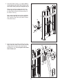
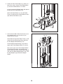
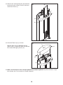
3
3. Attach the upper end of the Upright (72) to the
upper end of the Tower Frame (1) with two M10
x 30mm Socket Patch Screws (30) and two
M10 Washers (31). Do not tighten the Socket
Patch Screws yet.
2
2. Orient the Tower Frame (1) as shown. Have a
second person hold the Tower Frame to pre-
vent it from falling until you complete step 4.
Remove the two M10 x 30mm Socket Patch
S
crews (30), the two M10 Washers (31), and
the Small Pulley Bracket (6) from the back of
the Tower Frame (1).
Next, remove the M10 Locknut (32), the M10 x
50mm Socket Bolt (29), the two M10 Washers
(31), and the Large Pulley (24) from the Small
Pulley Bracket (6).
31
31
31
31
31
29
6
1
1
30
24
32
72
30

9
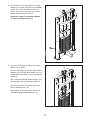
4
4. Insert the Weight Cable (40) through the Tower
Frame (1) as shown.
A
ttach the lower end of the Upright (72) to the
lower end of the Tower Frame (1) with four M10
x
35mm Socket Patch Screws (76) and four
M10 Washers (31).
See step 3. Tighten the two M10 x 30mm
Socket Patch Screws (30).
1
72
31
40
31
76
76
5
5. Route the Weight Cable (40) upward through
the Small Pulley Bracket (6).
Attach the Large Pulley (24) inside the Small
Pulley Bracket (6) with the M10 x 50mm Socket
Bolt (29), the two M10 Washers (31), and the
M10 Locknut (32) that you removed in step 2.
Then, attach the Small Pulley Bracket (6) to the
Tower Frame (1) with the two M10 x 30mm
Socket Patch Screws (30) and the two M10
Washers (31) that you removed in step 2.
31
31
31
29
6
1
30
24
40
32

10
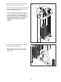
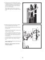
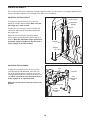
7
7. Loosen the two M8 x 35mm Set Screws (19) a
few complete turns; it is not necessary to
remove the Set Screws.
Look under the top of the Tower Frame (1) and
remove the two 25mm Snap Rings (39) from
the two Weight Guide Bushings (18).
Lift the Weight Guide Bushings (18) until the
upper ends of the Weight Guides (7) are free.
Next, tip the upper ends of the Weight Guides
(7) forward or backward, and slide the two
25mm Snap Rings (39), the Drop-down Weight
(10), the two Upper Weight Bumpers (16), and
the Top Weight (9) upward off the Weight
Guides.
10
16
9
19
18
18
19
7
1
6
6. Identify the Rear Shroud Base (3), which has a
hole in the center, and the Front Shroud Base
(4). Orient the Shroud Bases as shown.
Insert the end of the Weight Cable (40) upward
t
hrough the Rear Shroud Base (3).
Attach the Shroud Bases (3, 4) to the Tower
Frame (1) with four M6 x 15mm Button Screws
(35) and four M6 Washers (34).
4
1
3
40
34
35
34
35
39
16

11
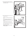
9
9. Orient the Top Weight (9) and the Drop-down
Weight (10) as shown.
Slide the Top Weight (9), the two Upper Weight
Bumpers (16), the Drop-down Weight (10), and
the two 25mm Snap Rings (39) onto the Weight
Guides (7).
Next, slide the two Weight Guide Bushings (18)
onto the upper ends of the Weight Guides (7).
Attach the two 25mm Snap Rings (39) to the
Weight Guide Bushings (18).
Then, tighten the two M8 x 35mm Set Screws
(19) into the Weight Guide Bushings (18).
19
19
18
18
9
8
8. Look at the decals on the eighteen 10-pound
Weights (8). Find the decal that has the largest
number on it. Orient that Weight so that the
d
ecal is facing the Upright (72), and slide the
Weight onto the Weight Guides (7).
Repeat this step until all eighteen Weights
(8) are on the Weight Guides (7).
8
72
8
7
7
39
16
10

12
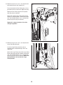
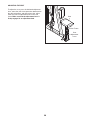
10
10. Remove all parts (23, 29, 31, and 32) from the
pulley bracket on the Tower Frame (1).
R
oute the Weight Cable (40) through the pulley
bracket and downward through the hole in the
c
enter of the Tower Frame (1).
Attach the Small Pulley (23) inside the pulley
bracket with the M10 x 50mm Socket Bolt (29),
the two M10 Washers (31), and the M10
Locknut (32) that you just removed. Make sure
that the Weight Cable (40) is between the
Small Pulley and the rod on the pulley
bracket.
32
1
31
23
Rod
31
29
4
0
11
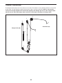
11. Tighten the end of the Weight Cable (40) into
the Large Pulley Bracket (60).
Then, tighten the jam nut on the end of the
Weight Cable (40) against the Large Pulley
Bracket (60).
40
60
Jam Nut

13
13
45
56
56
52
51
56
39
39
72
13. Identify the Cam Axles (52), which are longer
than the Handlebar Axles (not shown).
Attach a 25mm Snap Ring (39) to one end of a
Cam Axle (52).
Identify the Left Cam (45) and a Cam Arm (51)
and orient them as shown.
Have a second person hold the Left Cam (45),
the round tube on the Cam Arm (51), and three
Plastic Washers (56) inside the left bracket on
the Upright (72).
Insert the Cam Axle (52) into the Left Cam (45),
the Plastic Washers (56), and the Cam Arm
(51).
Attach a 25mm Snap Ring (39) to the other end
of the Cam Axle (52).
Repeat this step on the other side of the
strength equipment.
12
12. Tighten the end of the Weight Cable (40) into
the Weight Selector (11) until the Top Weight (9)
is lifted off the Weights (8). Then, loosen the
e
nd of the Weight Cable until the Top Weight
just rests on the Weights.
Then, tighten the jam nut on the end of the
Weight Cable (40) against the Weight Selector
(11).
11
9
40
8
Jam Nut

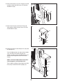
14
15
15. Attach a 25mm Snap Ring (39) to one end of a
Handlebar Axle (53).
Identify the Left Handlebar (48) and orient it as
shown.
Have a second person hold the round tube on
the Left Handlebar (48) and two Plastic
Washers (56) inside the bracket on the left Cam
Arm (51).
Insert the Handlebar Axle (53) into the Left
Handlebar (48) and the Plastic Washers (56).
Attach a 25mm Snap Ring (39) to the other end
of the Handlebar Axle (53).
Repeat this step on the other side of the
strength equipment.
48
56
56
51
53
39
39
14
7
5
72
50
80
14. Attach the Head Pad (50) to the Upright (72)
with three M8 x 25mm Socket Screws (75) and
three M8 Washers (80).

15
17. Remove all parts (24, 29, 31, and 32) from the
Large Pulley Bracket (60).
Insert the Large Pulley (24) that you just
removed into the indicated loop in the Cam
Cable (44).
Attach the Large Pulley (24) to the Large Pulley
Bracket (60) with the M10 x 50mm Socket Bolt
(29), the two M10 Washers (31), and the M10
Locknut (32) that you just removed. Make sure
that the Washers are outside the Large
Pulley Bracket.
31
31
24
60
29
44
40
32
17
Jam
Nut
16
16. Remove all parts (31, 32, 41, and 42) from the
indicated bracket on the Upright (72).
P
ress the end of the Cam Cable (44) as far as
possible into the socket on the Right Cam (38).
Route the Cam Cable (44) over the V-pulley
(42) that you just removed.
Attach the V-pulley (42) to the bracket on the
Upright (72) with the M10 x 70mm Socket Bolt
(41), the two M10 Washers (31), and the M10
Locknut (32) that you just removed.
Repeat this step on the other side of the
strength equipment.
31
38
42
72
41
44
3
1
32

16
19
19. Attach the Seat (62) to the Seat Frame (59)
with two M8 x 25mm Socket Screws (75) and
two M8 Washers (80).
62
59
80
75
80
75
20. Remove the M10 x 18mm Stop Screw (70) from
the Upright (72).
Press the Adjustment Lever (66) on the Upright
(72), insert the Seat Frame (59) into the
Upright, and then release the Adjustment Lever
into one of the adjustment holes in the Seat
Frame.
Make sure that the Adjustment Lever (66) is
firmly engaged in an adjustment hole.
Then, tighten the M10 x 18mm Stop Screw (70)
that you just removed into the Upright (72).
59
Holes
66
70
72
20
18. Attach the Backrest (61) to the Upright (72) with
two M8 x 25mm Socket Screws (75) and two
M8 Washers (80).
6
1
72
75
80
80
75
1
8

17
21
21. Look at the four Shrouds (36), and identify the
two Shrouds that have strips of Inner Trim (37)
and the two Shrouds that do not.
Slide the Shroud Panel (46) downward onto the
t
wo Shrouds (36) that do not have strips of
Inner Trim (37).
46
36
36
37
36
36
22
22. Slide the two Shrouds (36) with the Shroud
Panel (46) downward into the two strips of
Outer Trim (5) on the back of the Tower Frame
(1).
36
36
5
5
1
46

18
2
3
24
24. Orient the Tower Cap (2) as shown.
Slide the Tower Cap (2) downward onto the
Tower Frame (1). Attach the Tower Cap with two
M4 x 13mm Self-tapping Screws (27).
25. Make sure that all parts of the strength equipment are properly tightened. To protect the floor or carpet
from damage, place a mat under the strength equipment.
23. Slide the two remaining Shrouds (36) downward
into the two strips of Outer Trim (5) on the front
of the Tower Frame (1).
36
36
5
5
1
2
27
27
1

19
ADJUSTMENT
T
his section explains how to adjust the strength equipment. Make sure all that parts are properly tightened each
time the strength equipment is used. Replace any worn parts immediately.
ADJUSTING THE RESISTANCE
To change the amount of resistance, insert the
weight pin into the desired weight. Make sure that
the weight pin is fully inserted.
To add 5 lbs. (2.25 kg) of resistance, pull the indi-
cated knob and lower the drop-down weight onto
the weight stack.
When you are not using the drop-down weight,
slide it upward and engage the knob into the latch
bracket. Move the drop-down weight upward and
downward slightly to make sure that the knob is
firmly engaged in the latch bracket.
Cam Arm
Cam Arm
Cam
Cam
Adjustment
Knob
ADJUSTING THE CAM ARMS
To adjust the position of each cam arm, pull the
cam adjustment knob downward, move the cam
arm to the desired position, and then release the
cam adjustment knob into an adjustment hole in the
cam. Make sure that the cam adjustment knob is
firmly engaged in an adjustment hole.
Make sure to adjust both cam arms to the same
position.
Knob
Drop-down
Weight
L
atch Bracket
Weights
Weight
Pin
Cam
Adjustment
Knob

20
ADJUSTING THE SEAT
To adjust the seat, press the indicated adjustment
l
ever, move the seat frame upward or downward to
the desired position, and then release the adjust-
m
ent lever into an adjustment hole in the seat
frame. Make sure that the adjustment lever is
firmly engaged in an adjustment hole.
Seat
Adjustment
Lever
Seat Frame
S
eat
Page is loading ...
Page is loading ...
Page is loading ...
Page is loading ...
Page is loading ...
Page is loading ...
Page is loading ...
Page is loading ...
-
 1
1
-
 2
2
-
 3
3
-
 4
4
-
 5
5
-
 6
6
-
 7
7
-
 8
8
-
 9
9
-
 10
10
-
 11
11
-
 12
12
-
 13
13
-
 14
14
-
 15
15
-
 16
16
-
 17
17
-
 18
18
-
 19
19
-
 20
20
-
 21
21
-
 22
22
-
 23
23
-
 24
24
-
 25
25
-
 26
26
-
 27
27
-
 28
28


FreeMotion FLY/REAR DELT F806.0 Owner's manual
- Type
- Owner's manual
Ask a question and I''ll find the answer in the document
Finding information in a document is now easier with AI
Related papers
-
FreeMotion EPIC F801.0 Owner's manual
-
-
-
-
-
-
-
-
-
Other documents
-
Titan Fitness Linebacker Squat Landmine Attachment v2 User manual
-
 Firesense 62110 User manual
-
Weider WEEVSY1909 User manual
-
NordicTrack NTSY24918F.0 User manual
-
Star Trac Inspiration Strenght IP-S1316 Installation guide
-
-
-
Epic 700 Vx User manual
-
Life Fitness Ab Crunch User manual
-
Gold's Gym XRS 50 User manual
