Invacare R110 User manual

Category
Kitchen scales
Type
User manual
This manual MUST be given to the user of the product.
BEFORE using this product, read this manual and save for future reference.
User Manual EN
Invacare
®
Reliant™ 450 RPL450-2
Invacare
®
Reliant 600 RPL600-2
Electric Mobile Patient Lift
Electric Portable Patient Lift 2 Part No. 1145810
© 2013 Invacare Corporation. All rights reserved. Republication, duplication or modification in whole or in part is prohibited without prior
written permission from Invacare. Trademarks are identified by ™ and ®. All trademarks are owned by or licensed to Invacare Corporation
or its subsidiaries unless otherwise noted.
Part No. 1145810 3 Electric Portable Patient Lift
1 GENERAL 5
Symbols ........................................................................................................5
Warnings................................................................................................5
Limited Warranty ......................................................................................6
2SAFETY 7
General Guidelines ....................................................................................7
Operating Information..............................................................................7
General...................................................................................................7
Pinch Points and Positioning..............................................................8
Assembling the Lift ..............................................................................8
Operating the Lift ................................................................................8
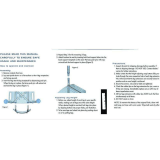
Using the Sling ......................................................................................9
Lifting the Patient.................................................................................9
Transferring the Patient .................................................................. 10
Performing Maintenance.................................................................. 10
Electrical and Grounding................................................................. 11
Disposal............................................................................................... 11
Radio Frequency Interference.............................................................. 11
3 PRODUCT LABELING 12
4 TECHNICAL DATA 13
Patient Lift................................................................................................. 13
Full Body, Divided Leg and Toileting Slings....................................... 14
Reliant Scale RLS6................................................................................... 14
5 ASSEMBLY 15
Introduction..............................................................................................15
Unpacking the Patient Lift .....................................................................15
Assembling the Mast to the Base.........................................................16
Assembling the Boom Actuator...........................................................17
Installing the Leg Actuator to the Base..............................................18
Mounting the Battery Charger.............................................................19
6OPERATION 20
Introduction..............................................................................................20
Using the Hand Control Buttons ........................................................20
Raising/Lowering the Boom............................................................20
Opening/Closing the Legs ...............................................................20
Activating a Mechanical Emergency Release .....................................21
Performing an Emergency Stop............................................................22
Charging the Battery ..............................................................................23
7 LIFTING THE PATIENT 24
Introduction..............................................................................................24
Positioning the Patient Lift ....................................................................24
Attaching a Sling.......................................................................................25
Lifting/Moving the Patient......................................................................26
User Manual
DEALER: This manual MUST be given to the user of the product.
USER:
BEFORE using this product, read this manual and save for future reference.
Electric Mobile Patient Lift
CONTENTS
Electric Portable Patient Lift
4 Part No. 1145810
8 TRANSFERRING THE PATIENT 28
Introduction ............................................................................................. 28
Transferring to a Commode Chair..................................................... 29
Transferring to a Standard Commode............................................... 30
Transferring to a Bathing Unit ............................................................. 30
Transferring to a Wheelchair............................................................... 31
9 TROUBLESHOOTING 32
10 MAINTENANCE 33
Maintenance Safety Inspection Checklist........................................... 33
Lubricating the Lift.................................................................................. 35
Detecting Wear and Damage............................................................... 36
Cleaning the Sling and the Lift.............................................................. 36
Replacing the Boom Actuator.............................................................. 36
Checking and Tightening Mast Pivot Bolt.......................................... 37
Replacing the Hanger bar...................................................................... 38
Maintaining the Base Adjustment........................................................ 39
Replacing Casters/Forks........................................................................ 40
Replacing Rear Casters.................................................................... 40
Replacing Front Casters.................................................................. 41
Replacing Forks ................................................................................. 41
11 ACCESSORIES 42
Reliant Scale RLS6...................................................................................42
Removing the Hanger bar ...............................................................42
Installing the Reliant Scale ...............................................................44
Operating the Scale ................................................................................46
Keypad Functions..............................................................................46
Weighing the Patient ..............................................................................47
Replacing the Battery .............................................................................48
Calibrating the Reliant Scale ...........................................................49
Troubleshooting ......................................................................................50
Display Codes....................................................................................50
1 GENERAL
Part No. 1145810
5 Electric Portable Patient Lift
1 General
1.1 Symbols
Warnings
Signal words are used in this manual and apply to hazards or unsafe practices which could result in personal injury or property damage. See the
information below for definitions of the signal words.
DANGER
Danger indicates an imminently hazardous situation which, if not avoided, will result in death or serious injury.
WARNING
Warning indicates a potentially hazardous situation which, if not avoided, could result in death or serious injury.
CAUTION
Caution indicates a potentially hazardous situation which, if not avoided, may result in property damage or minor injury or
both.
!
IMPORTANT
Indicates a hazardous situation that could result in damage to property if it is not avoided.
Gives useful tips, recommendations and information for efficient, trouble-free use.
1 GENERAL
Electric Portable Patient Lift
6 Part No. 1145810
1.2 Limited Warranty
This warranty is extended only to the original purchaser/user of our products.
This warranty gives you specific legal rights and you may also have other legal rights which vary from state to state.
Invacare warrants the products manufactured to be free from defects in materials and workmanship for a period of three years on the lift and one year
on the slings and electric components from the date of purchase. If within such warranty period any such product shall be proven to be defective, such
product shall be repaired or replaced, at Invacare’s option. This warranty does not include any labor or shipping charges incurred in replacement part
installation or repair of any such product. Invacare’s sole obligation and your exclusive remedy under this warranty shall be limited to such repair and/or
replacement.
For warranty service, please contact the dealer from whom you purchased your Invacare product. In the event you do not receive satisfactory warranty
service, please write directly to Invacare at the address on the back cover, provide dealer’s name, address, date of purchase, indicate nature of the
defect.
Invacare Corporation will issue a serialized return authorization. The defective unit or parts MUST be returned for warranty inspection using the serial
number, when applicable as identification within 30 days of return authorization date. Do not return products to our factory without our prior consent.
C.O.D. shipments will be refused; please prepay shipping charges.
LIMITATIONS AND EXCLUSIONS: THE FOREGOING WARRANTY SHALL NOT APPLY TO SERIAL NUMBERED PRODUCTS IF THE SERIAL
NUMBER HAS BEEN REMOVED OR DEFACED, PRODUCTS SUBJECTED TO NEGLIGENCE, ACCIDENT, IMPROPER OPERATION,
MAINTENANCE OR STORAGE, PRODUCTS MODIFIED WITHOUT INVACARE’S EXPRESS WRITTEN CONSENT (INCLUDING, BUT NOT
LIMITED TO, MODIFICATION THROUGH THE USE OF UNAUTHORIZED PARTS OR ATTACHMENTS; PRODUCTS DAMAGED BY REASON
OF REPAIRS MADE TO ANY COMPONENT WITHOUT THE SPECIFIC CONSENT OF INVACARE, OR TO A PRODUCT DAMAGED BY
CIRCUMSTANCES BEYOND INVACARE’S CONTROL, AND SUCH EVALUATION WILL BE SOLELY DETERMINED BY INVACARE. THE
WARRANTY SHALL NOT APPLY TO PROBLEMS ARISING FROM NORMAL WEAR OR FAILURE TO ADHERE TO THE INSTRUCTIONS IN
THIS MANUAL.
THE FOREGOING WARRANTY IS EXCLUSIVE AND IN LIEU OF ANY OTHER EXPRESS WARRANTIES. IMPLIED WARRANTIES, IF ANY,
INCLUDING THE IMPLIED WARRANTIES OF MERCHANTABILITY AND FITNESS FOR A PARTICULAR PURPOSE, SHALL NOT EXTEND
BEYOND THE DURATION OF THE EXPRESSED WARRANTY PROVIDED HEREIN AND THE REMEDY FOR VIOLATIONS OF ANY IMPLIED
WARRANTY SHALL BE LIMITED TO REPAIR OR REPLACEMENT OF THE DEFECTIVE PRODUCT PURSUANT TO THE TERMS CONTAINED
HEREIN. INVACARE SHALL NOT BE LIABLE FOR ANY CONSEQUENTIAL OR INCIDENTAL DAMAGES WHATSOEVER.
SOME STATES DO NOT ALLOW EXCLUSION OR LIMITATION OF INCIDENTAL OR CONSEQUENTIAL DAMAGE, OR LIMITATION ON
HOW LONG AN IMPLIED WARRANTY LASTS, SO THE ABOVE EXCLUSIONS AND LIMITATIONS MAY NOT APPLY TO YOU.
THIS WARRANTY SHALL BE EXTENDED TO COMPLY WITH STATE OR PROVINCIAL LAWS AND REQUIREMENTS.
PLEASE NOTE: THE WARRANTY BELOW HAS BEEN DRAFTED TO COMPLY WITH FEDERAL LAW
APPLICABLE TO PRODUCTS MANUFACTURED AFTER JULY 4, 1975.
2 SAFETY
Part No. 1145810
7 Electric Portable Patient Lift
2 Safety
The Safety section contains important information for the safe operation and use of this product.
2.1 General Guidelines
Check all parts for shipping damage before using. In case of damage, DO NOT use the equipment. Contact the Dealer for further instructions.
2.2 Operating Information
General
WARNING
DO NOT use this product or any available optional equipment without first completely reading and understanding these instructions and
any additional instructional material such as owner’s manuals, service manuals or instruction sheets supplied with this product or optional
equipment. If you are unable to understand the warnings, cautions or instructions, contact a healthcare professional, dealer or technical
personnel before attempting to use this equipment - otherwise, injury or damage may occur.
ACCESSORIES WARNING
Invacare products are specifically designed and manufactured for use in conjunction with Invacare accessories. Accessories designed by
other manufacturers have not been tested by Invacare and are not recommended for use with Invacare products.
!
NOTICE
THE INFORMATION CONTAINED IN THIS DOCUMENT IS SUBJECT TO CHANGE WITHOUT NOTICE.
WARNING
The Invacare patient lift is NOT a transport device. It is intended to transfer an individual from one resting surface to another (such as a bed
to a wheelchair). Otherwise injury or damage may occur.
DO NOT attempt any transfer without approval of the patient’s physician, nurse or medical assistant. Thoroughly read the instructions in
this Owner’s Manual, observe a trained team of experts perform the lifting procedures and then perform the entire lift procedure several
times with proper supervision and a capable individual acting as a patient.
Use common sense in all lifts. Special care MUST BE taken with people with disabilities who cannot cooperate while being lifted.
Invacare slings and patient lift accessories are specifically designed to be used in conjunction with Invacare patient lifts. Slings and accessories
designed by other manufacturers are not to be utilized as a component of Invacare’s patient lift system.
If the patient lift is exposed to extreme temperature (above 100°F or below 32°F), high humidity and/or becomes wet, prior to use, ensure
handgrips do not twist on patient lift handle - otherwise damage or injury may occur.
2 SAFETY
Electric Portable Patient Lift
8 Part No. 1145810
Pinch Points and Positioning
Assembling the Lift
Operating the Lift
WARNING
Pinch points exist between boom and hanger bar. Pinch
points also exist at base of lift. When positioning lift, be
aware of the position of the hanger bar and the patient.
Injury could occur.
Between Boom
and hanger bar
Base of Lift
WARNING
DO NOT overtighten mounting hardware. This will damage mounting brackets.
WARNING
Although Invacare recommends that two assistants be used for all lifting preparation, transferring from and transferring to procedures, our
equipment will permit proper operation by one assistant. The use of one assistant is based on the evaluation of the health care professional
for each individual case.
Make sure there is an audible click when mounting battery on the battery charger to confirm proper mounting. Otherwise, injury or
damage may occur.
DO NOT exceed maximum weight limitation of the patient lift. The weight limitation for the RPL450-2 is 450 lbs. The weight limitation for
the RPL600-2 is 600 lbs.
ALWAYS keep hands and fingers clear of moving parts to avoid injury.
2 SAFETY
Part No. 1145810
9 Electric Portable Patient Lift
Using the Sling
Lifting the Patient
WARNING
Use an Invacare approved sling that is recommended by the individual’s doctor, nurse or medical assistant for the comfort and safety of the
individual being lifted.
DO NOT use any kind of plastic back incontinence pad or seating cushion between patient and sling material that may cause the patient to
slide out of the sling during transfer.
After each laundering (in accordance with instructions on the sling), inspect sling(s) for wear, tears, and loose stitching.
Bleached, torn, cut, frayed, or broken slings are unsafe and could result in injury. Discard immediately.
DO NOT alter slings.
Be sure to check the sling attachments each time the sling is removed and replaced, to ensure that it is properly attached before the patient
is removed from a stationary object (bed, chair or commode).
If the patient is in a wheelchair, secure the wheel locks in place to prevent the chair from moving forwards or backwards.
When connecting slings equipped with color coded straps to the patient lift, the shortest of the straps MUST be at the back of patient for
support. Using long section will leave little or no support for patient's back. The loops of the sling are color coded and can be used to place
patient in various positions. The colors make it easy to connect both sides of the sling equally. Make sure that there is sufficient head
support when lifting a patient.
WARNING
When using an adjustable base lift, the legs MUST be in the maximum Opened/Locked position before lifting the patient.
When elevated a few inches off the surface of the stationary object (wheelchair, commode, or bed) and before moving the patient, check
again to make sure that the sling is properly connected to the hooks of the hanger bar. If any attachments are not properly in place, lower
the patient back onto the stationary object (wheelchair, commode, or bed) and correct this problem.
Adjustments for safety and comfort should be made before moving the patient. Patient's arms should be inside of the straps.
Invacare slings are made specifically for use with Invacare Patient Lifts. For the safety of the patient, DO NOT intermix slings and patient
lifts of different manufacturers. Warranty will be voided.
During transfer, with patient suspended in a sling attached to the lift, DO NOT roll caster base over uneven surfaces that could cause the
patient lift to tip over. Use steering handle on the mast at all times to push or pull the patient lift.
Invacare does not recommend locking of the rear casters of the patient lift when lifting an individual. Doing so could cause the lift to tip and
endanger the patient and assistants. Invacare does recommend that the rear casters be left unlocked during lifting procedures to allow the
patient lift to stabilize itself when the patient is initially lifted from a chair, bed or any stationary object.
2 SAFETY
Electric Portable Patient Lift
10 Part No. 1145810
Transferring the Patient
Performing Maintenance
WARNING
When elevated a few inches off the surface of the stationary object (wheelchair, commode, or bed) and before moving the patient, check
again to make sure that the sling is properly connected to the hooks of the hanger bar. If any attachments are not properly in place, lower
the patient back onto the stationary object (wheelchair, commode, or bed) and correct this problem.
Wheelchair wheel locks MUST be in a locked position before lowering the patient into the wheelchair for transport.
Before transferring, check that the wheelchair weight capacity can withstand the patient's weight.
Be sure to check the sling attachments each time the sling is removed and replaced, to ensure that it is properly attached before the patient
is removed from the bed or chair.
Mast pivot under the rubber boot must be tight to ensure safe use of the patient lift. Bolt must be checked at least every six months in
conjunction with periodic maintenance.
WARNING
Maintenance MUST be performed ONLY by qualified personnel.
After the first year of use, the hooks of the hanger bar and the mounting brackets of the boom should be inspected every three months to
determine the extent of wear. If these parts become worn, replacement must be made.
Casters and axle bolts require inspections every six months to check for tightness and wear.
After the first twelve months of operation, inspect the hanger bar and the eye of the boom (to which it attaches) for wear. If the metal is
worn, the parts MUST be replaced. Make this inspection every six months thereafter.
Regular maintenance of patient lifts and accessories is necessary to assure proper operation.
DO NOT overtighten mounting hardware. This will damage mounting brackets.
After the first six months of operation, inspect all pivot points and fasteners for wear. If the metal is worn, the parts MUST be replaced.
Make this inspection every six months.
2 SAFETY
Part No. 1145810
11 Electric Portable Patient Lift
Electrical and Grounding
Disposal
2.3 Radio Frequency Interference
WARNING
GROUNDING INSTRUCTIONS
DO NOT, under any circumstances, cut or remove the round grounding prong from any plug used with or for Invacare products. Some
devices are equipped with three-prong (grounding) plugs for protection against possible shock hazards. Where a two-prong wall receptacle
is encountered, it is the personal responsibility and obligation of the customer to contact a qualified electrician and have the two-prong
receptacle replaced with a properly grounded three-prong wall receptacle in accordance with the National Electrical Code. If you must use
an extension cord, use ONLY a three-wire extension cord having the same or higher electrical rating as the device being connected. In
addition, Invacare has placed RED/ORANGE warning tags on some equipment. DO NOT remove these tags.
Carefully read battery/battery charger information prior to installing, servicing or operating your patient lift.
WARNING
This product has been supplied from an environmentally aware manufacturer that complies with the Waste Electrical and Electronic
Equipment (WEEE) Directive 2002/96/CE.
DO NOT dispose of batteries in normal household waste. Device contains lead acid batteries. They MUST be taken to a proper disposal
site. Contact your local waste management company for information.
This product may contain substances that could be harmful to the environment if disposed of in places (landfills) that are not appropriate
according to legislation.
Please be environmentally responsible and recycle this product through your recycling facility at its end of life.
WARNING
Most electronic equipment is influenced by Radio Frequency Interference (RFI). CAUTION should be exercised with regard to the use of
portable communication equipment in the area around such equipment. If RFI causes erratic behavior, PUSH the Red Power Switch OFF
IMMEDIATELY. DO NOT turn the Power Switch ON while transmission is in progress.
3 PRODUCT LABELING
Electric Portable Patient Lift
12 Part No. 1145810
3 Product Labeling
BEFORE using the Patient
Lift, READ and
UNDERSTAND the Owner’s
Manual for proper
operation and safety
procedures.
WEIGHT LIMITATION 600 lbs.
The Invacare Patient lift is
NOT a transport device.
DO NOT roll casterbase over
uneven surfaces that may
cause the Patient Lift to tip
over.
DO NOT lock the casters of
the Patient Lift when lifting an
individual. Casters MUST be
left unlocked to allow Patient
Lift to stabilize during lifting
procedures.
USE ONLY Invacare slings
and lift accessories.
For maintenance and
replacement, use only
components designed for this
patient lift model. See the
product label for model
information.
Customer Service
1-800-333-6900
1070965 Rev B
4 TECHNICAL DATA
Part No. 1145810
13 Electric Portable Patient Lift
4 Technical Data
4.1 Patient Lift
450 LB. ELECTRIC 600 LB. ELECTRIC
LOW PROFILE
RPL450-2
LOW PROFILE
RPL600-2
Height at Sling Hook-up - MAX.: 74 inches 68 inches
Height at Sling Hook-up - MIN.: 24 inches 28 inches
Base Width OPEN: 41.0 inches
Base Width CLOSED: 26.5 inches
Base Height (Clearance): 4.5 inches
Base Length: 48.0 inches
Caster Size (FRONT/REAR): 3.0/5.0 inches
Sling Options: 3 Styles 1 Style
Weight Capacity: 450 lbs 600 lbs
Weight IN Carton: 136 lbs 141 lbs
Weight OUT of Carton: 109 lbs 115 lbs
Battery: 24V DC (RCHBL)
Charger Input: 100-240V AC
Charger Output/Charging Time: 29.5V DC Max 6 hrs
Accessories: Digital Scale
Audio Low Battery Alarm: Yes
Motor Safety Devices: Anti-Entrapment
Approx. Lifts per Charge
(Varies depending upon load and stroke):
100-200 Cycles per charge
Warranty Electronics: 1 Year
4 TECHNICAL DATA
Electric Portable Patient Lift
14 Part No. 1145810
4.2 Full Body, Divided Leg and Toileting Slings
4.3 Reliant Scale RLS6
FULL BODY FULL BODY
W/COMMODE
DIVIDED LEG TOILETING HEAVY
DUTY W/O
COMMODE
HEAVY
DUTY W/
COMMODE
R110
R112*
R111
R113*
R114 R115 R116 R117* R100P R100 R101 R102 R121 R140* R141*
Size: M LXLM LXLP M LXL L N/A N/A
Width: 41.5 45.5 45.5 41.5 45.4 45.5 33 37.5 41 44.5 36 45 45
Commode Opening: N/A N/A N/A 8 8 9 N/A N/A N/A N/A N/A N/A 7
Length: 54.760.565.354.760.565.359.862.867.872.3 37 55 55
Commode Opening: N/A N/A N/A 11 11 13 N/A N/A N/A N/A N/A N/A 13
Back: N/A N/A N/A N/A N/A N/A 29.2 35.7 41.7 43.2 N/A N/A N/A
Weight Capacity
(lbs):
450 450 450 450 450 450 450 450 450 450 450 600 600
*Slings made of a mesh material.
All dimensions are in inches except where noted.
Weight Range: Up to 600 Lbs. (272.7 Kg)
Resolution: +/- 0.2 Lbs (.1 Kg)
Display: Liquid Crystal Digital
Automatic Power Down: Two (2) minutes
Size: 5-3/4 L X 3-5/8 W X 4 H
Weight: .55 Lbs
Power: Nine (9) Volt Alkaline battery (included)
Battery Life: Approximately 1500 readings
Temperature Range: 50° To 104°F (10° To 40°C)
5 ASSEMBLY
Part No. 1145810
15 Electric Portable Patient Lift
5 Assembly
5.1 Introduction
5.2 Unpacking the Patient Lift
1. Unpack the components from the shipping carton.
WARNING
Use only Invacare parts in the assembly of this patient lift. The base legs, mast, boom assembly and the hanger bar are manufactured to
specifications that assure correct alignment of all parts for safe functional operation.
DO NOT remove the plastic wrap that secures the
boom to the mast. The plastic wrap will be removed in
Assembling the Boom Actuator
on page 17.
DO NOT remove
plastic wrap at this time
5 ASSEMBLY
Electric Portable Patient Lift
16 Part No. 1145810
5.3 Assembling the Mast to the Base
1. If locking-type casters are on the patient lift, lock them.
2. Remove the shoulder bolt, nut and washer, that secures the mast
in the U-shape cut-out of the base.
3. Position the mast in an upright position and place the mast into the
U-shaped cut-out of the base.
4. Insert shoulder bolt with washers through the base and mast.
5. Secure with nut.
WARNING
The mast may be removed from the base for storage or
transporting. Each time the mast is removed and
returned to the base, the mast MUST be properly
secured to the base assembly.
Step here to
LOCK.
Step here to UNLOCK.
Locking
Lever
Washers
Shoulder Bolt
Nut
U-shaped
Cutout
Mast
Mast
Base
5 ASSEMBLY
Part No. 1145810
17 Electric Portable Patient Lift
5.4 Assembling the Boom Actuator
1. Remove the shoulder bolt, washer and nut from the mounting
bracket on the boom assembly.
2. Unpack the pinch guard from the patient lift carton.
3. Cut the plastic-wrap that secures the boom and mast together.
4. Lift-up on the boom and place it on your left shoulder.
5. Let the boom actuator rest on your shoulder and rotate the shaft
extension of the actuator assembly until it lines-up with the
mounting holes in the boom assembly.
6. Place the pinch guard over the shaft extension of the boom
actuator.
7. Align the holes of the boom assembly mounting bracket with those
of the boom actuator and insert the bolt. Secure with nut.
CAUTION
DO NOT overtighten the nut and bolt. This damages
the mounting bracket.
The bottom of the boom actuator assembly will already
be assembled to the mast mounting bracket.
Be sure that the bolt is completely through the holes of
the boom assembly mounting bracket and the actuator
assembly. The boom assembly will pivot easily if the
mounting hardware is aligned properly when the boom
assembly is secured to the mast.
Pinch Guard
Mounting Bracket
Turn 90°
Boom Actuator
Shoulder Bolt
Washer
Nut
Mast Mounting Bracket
Boom Actuator
Shaft Extension
Boom
Assembly
5 ASSEMBLY
Electric Portable Patient Lift
18 Part No. 1145810
5.5 Installing the Leg Actuator to the Base
1. Slide the leg actuator into the slot in the base of the patient lift
(Detail B).
2. Perform the following to secure the leg actuator to the pivot
bracket (Detail A):
A. Turn the patient lift on its side.
B. Position slot in leg actuator over the pivot bracket.
C. Install the pin through the leg actuator and pivot bracket and
secure with hitch pin.
D. Return the patient lift to the upright position.
3. Perform the following to secure the leg actuator to the mast
bracket:
A. Position leg actuator between mast brackets.
B. Move the legs to align the holes in the leg actuator with the
holes in the mast bracket.
C. Install the pin through the holes of the leg actuator and mast
bracket and secure with hitch pin.
4. Plug the hand control control (not shown) into the bottom of the
control box.
WARNING
Ensure that there is sufficient room to turn patient lift
on its side and that floor area is clear of debris.
Otherwise, injury to personnel or damage to patient lift
may occur.
DETAIL “A” - SIDE VIEW OF PATIENT LIFT
Pin
Pivot
Bracket
Leg
Actuator
Base
Leg
Mast Bracket
Pin
Boom Assembly
Leg Actuator
Boom Actuator
Slot in Base
Mast
Battery
Hitch Pin
Control Box
DETAIL “B”
Hitch
Pin
5 ASSEMBLY
Part No. 1145810
19 Electric Portable Patient Lift
5.6 Mounting the Battery Charger
1. Place the battery charger with mounting bracket on the wall at the desired position.
2. With a pencil, mark the middle hole position.
3. Measure down 6½ inches from the pencil mark and drill one mounting hole.
4. Install the bottom mounting screw until there is an approximate 1/8-inch gap between the screw head and the wall.
5. Install the battery charger with mounting bracket onto the bottom mounting screw.
6. Drill the remaining two mounting holes.
7. Install the two remaining mounting screws through the mounting bracket and into the wall. Tighten securely.
8. Plug the battery charger into the wall electrical outlet.
9. Verify that ON is illuminated.
Refer to your local regulations concerning proper mounting procedures.
Mounting Bracket
Mounting Screws
Battery Charger with
Mounting Bracket (STEP 5)
BOTTOM Mounting Screw (STEP 4)
6 OPERATION
Electric Portable Patient Lift
20 Part No. 1145810
6 Operation
6.1 Introduction
6.2 Using the Hand Control Buttons
The hand control is used to raise/lower the boom or to open/close the
legs of the base for stability when lifting a patient
Raising/Lowering the Boom
To raise the patient lift, press the boom up button (up arrow) to raise
the boom and the patient.
To lower the patient lift, press the boom down button (down arrow) to
lower the boom and the patient.
Opening/Closing the Legs
To open the legs, press the legs open button.
To close the legs, press the legs closed button.
WARNING
DO NOT attempt any transfer without approval of the patient's physician, nurse or medical assistant. Thoroughly read the instructions in
this Owner's Manual, observe a trained team of experts performing the lifting procedures and then perform the entire lift procedure
several times with proper supervision and a capable individual acting as a patient.
The legs of the lift must be in the maximum open position for optimum stability and safety. If it is necessary to close the legs of the lift to
maneuver the lift under a bed, close the legs of the lift only as long as it takes to position the lift over the patient and lift the patient off the
surface of the bed. When the legs of the lift are no longer under the bed, return the legs of the lift to the maximum open position.
Invacare recommends that two assistants be used for all lifting preparation and transferring to/from procedures; however, the patient lift can
be operated with one assistant. The use of one assistant is based on the evaluation of the health care professional for each individual case.
WARNING
DO NOT lock the rear casters of the patient lift when lifting an individual. Locking the rear casters could cause the patient lift to tip and
endanger the patient and assistants.
  • Page 1 1
  • Page 2 2
  • Page 3 3
  • Page 4 4
  • Page 5 5
  • Page 6 6
  • Page 7 7
  • Page 8 8
  • Page 9 9
  • Page 10 10
  • Page 11 11
  • Page 12 12
  • Page 13 13
  • Page 14 14
  • Page 15 15
  • Page 16 16
  • Page 17 17
  • Page 18 18
  • Page 19 19
  • Page 20 20
  • Page 21 21
  • Page 22 22
  • Page 23 23
  • Page 24 24
  • Page 25 25
  • Page 26 26
  • Page 27 27
  • Page 28 28
  • Page 29 29
  • Page 30 30
  • Page 31 31
  • Page 32 32
  • Page 33 33
  • Page 34 34
  • Page 35 35
  • Page 36 36
  • Page 37 37
  • Page 38 38
  • Page 39 39
  • Page 40 40
  • Page 41 41
  • Page 42 42
  • Page 43 43
  • Page 44 44
  • Page 45 45
  • Page 46 46
  • Page 47 47
  • Page 48 48
  • Page 49 49
  • Page 50 50
  • Page 51 51
  • Page 52 52

Invacare R110 User manual

Category
Kitchen scales
Type
User manual

Ask a question and I''ll find the answer in the document

Finding information in a document is now easier with AI