CADDX RANGER 7600 Installation guide
- Category
- Security access control systems
- Type
- Installation guide

TABLE OF CONTENTS
PAGE
GENERAL DESCRIPTION ............................................... 2
STANDARD AND OPTIONAL PARTS LIST .................................. 2
FEATURE DEFINITIONS ................................................ 3
TERMINAL DRAWING AND SPECIAL NOTES ............................... 4
TERMINAL DESCRIPTION ............................................... 5
HOW TO PROGRAM THE RANGER 7600 ..................................6
KEYPAD PROGRAMMING EXAMPLES ..................................... 7
OPTIONAL #8950 PROGRAMMER EXAMPLE ............................... 7
PROGRAMMING INSTRUCTIONS ...................................... 8-28
PROGRAMMING WORKSHEETS ..................................... 29-32
APPENDIX 1 .........................................................33
APPENDIX 2 .........................................................34
LOCAL TELEPHONE COMPANY INTERFACE INFORMATION .................35
NOTES ....................................................... 36
SPECIFICATIONS & WARRANTY ........................................38
RANGER 7600
DOWNLOADABLE CONTROL COMMUNICATOR
INSTALLATION MANUAL
CADDX CONTROLS, INC.
GLADEWATER, TEXAS
800-727-2339

2
RANGER 7600
INSTALLATION MANUAL
General Description
The Ranger 7600 is a versatile up/downloadable security control with four EOL supervised zones and two non-
supervised normally closed zones. Its microcomputer design provides some of the most versatile, yet easy to use
features available for most security applications today. Each of the four supervised zones can be programmed to
be one of ten different types including 24 Hour, Interior Follower, and Day zone. The two non-supervised zones can
be programmed for any of the available zone types excluding "FIRE". Each zone is individually annunciated and can
be bypassed from the keypad. See page 11 for a description of all zone types.
Read the USER’S MANUAL before you begin the installation for the best overall description of how the Ranger 7600
functions. After installation of the security system, complete the information on page 1 of the user’s manual and
explain the system operation to all security system owners/operators.
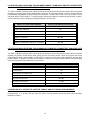
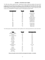
Standard Parts List
The Ranger 7600 is shipped with the parts listed below.
QUANTITY PART DESCRIPTION PART NO.
1 MASTER CONTROL PANEL W / O Keypad 7605
6 3.3K, ½ WATT E.O.L. RESISTORS EOL-33
1 INSTALLATION MANUAL IM-7600
1 USER’S MANUAL OM-7600
Optional Parts List.
The following parts are available for use with the Ranger 7600.
OPTIONAL PARTS DESCRIPTION PART NO.
LED REMOTE KEYPAD 8001, 8002, 8601
LCD ALPHA NUMERIC DISPLAY KEYPAD 9050
AC POWER SUPPLY 16.5V 25 VA T-16.5-25
PROGRAMMER WITH DIGITAL NUMERIC DISPLAY 8950
SMART PROGRAMMER WITH LCD DISPLAY 9075
DOWNLOADING SOFTWARE PACKAGE DL900

3
FEATURE DEFINITIONS
ALARM HISTORY - Five seconds after pressing the [0] key, the keypad will annunciate “Freeze Frame” alarm
history. The zone LED’s will indicate which zone(s) caused the last alarm, regardless of the number of times the
Ranger 7600 has been armed or disarmed since that alarm. It annunciates by blinking the zone LED(s) that caused
the alarm, and lighting steady those that were bypassed when that alarm occurred. The annunciation will continue
for 5 seconds. Alarm History is erased when the Ranger 7600 is put into the program mode. A burglary zone that
has been bypassed due to “Swinger Shutdown” will alternate between steady and blinking.
AUTOMATIC ARMING - The Ranger 7600 can be programmed to Automatically Arm at a predesignated time of day,
if it has not already been armed. (Page 22, Location 202.)
AUTOMATIC BYPASS/INSTANT ARMING - When enabled, the control panel can automatically bypass interior follower
zones if an exit is not detected during the delay time, and delayed zones can be made instant. (Page 16, Location 131.)
AUXILIARY OUTPUT - The 7600 has one auxiliary output that can be activated by up to four different events from a
pool of 16 different options. (Page 17, Locations 145-148.)
CHIME - If so programmed, this feature can be turned on and off by pressing [1]. When the system is in the disarmed
state, the violation of selected zones will create a one second tone through the keypad sounder. Chime is disabled
on all zones from factory. (Page 22 for Locations 186-191.)
CROSS ZONING - When enabled, the 7600 can be programmed for "Cross Zoning" (Page 25, Locations 244-249)
which is a feature that requires a trip on more than one zone during a specific time frame (Page 25, Location 255) to
verify an alarm condition.
DUAL/SPLIT REPORTING - The Ranger 7600 can be programmed for dual and/or split reporting.
DYNAMIC BATTERY TEST - When enabled, the Ranger 7600 can be programmed to perform a dynamic battery test
for a selected duration, at 6:00 AM. (Page 22, Location 203.)
ENTRY-GUARD - This unique low level arming mode has been developed to reduce the most common source of false
alarms. When armed in this mode, the opening of any zones designated as "Entry Guard zones" will initiate the keypad
sounder and start a delay before creating an alarm. This arming mode will encourage system owners to use their
system more frequently when the premises is occupied. (Page 25, Locations 244-249.)
FIRE ALARM VERIFICATION - When enabled, the Ranger 7600 has the ability to verify a Fire alarm by requiring more
than one trip on a smoke detector before creating an alarm. (Page 17, Location 143.)
FORCE ARMING - When enabled, the Ranger 7600 can be armed with zones violated, lacking a green "Ready" light
on the keypad. Under this condition, all zones that are not secure at the end of the exit delay will become bypassed.
All zones that become secured before the end of the exit delay will become active in the system. (Page 22, Location
197.)
GROUP BYPASS - Zones can be programmed to bypass as a group when the [rr][9][rr] keys are pressed while system
is disarmed. (Page 25, Locations 244-249.)
INTERNAL EVENT LOG - Up to 80 events can be stored in memory along with the date and time of the event. These
events can later be viewed through downloading.
KEYSWITCH ARMING - Keyswitch arming/disarming can be accomplished by using the remote arming input on the
PC board, and the auxiliary outputs. It is not necessary to waste a hardwire zone to accommodate Keyswitch
arming/disarming.
LCD KEYPAD - The 7600 will accommodate the Ranger 9050 custom English Language Keypad.
PAGER AND HIGH SPEED FORMATS - The 7600 has SIA and Contact ID high speed communicator formats. A
pager format is also available for reporting to a pager. (Page 9).
QUICK ARM FEATURE - The Ranger 7600 has a one button "Quick Arm" code which can be used to arm the system
by pressing one digit at the keypad. (Page 17, Location 139.)
SECONDARY EXIT DELAY - Used most often for garage doors, this zone type is a second entry/exit delay that has
its own delay times, independent of the standard entry/exit delay zone. (Page 20, Locations 178-179)

4
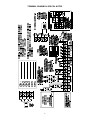
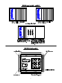
TERMINAL DRAWING & SPECIAL NOTES

5
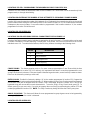
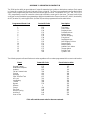
TERMINAL DESCRIPTION
DESCRIPTION
1
Connect one side of zone 1 loop. The other side of loop to common terminal 3. Open
or short causes alarm.
2
Connect one side of zone 2 loop. The other side of loop to common terminal 3. Open
or short causes alarm.
3
Loop Common For zones 1-3
4
Connect one side of zone 3 loop. The other side of loop to common terminal 3. Open
or short causes alarm.
5
Connect one side of zone 4 loop. The other side of loop to common terminal 6. Open
or short causes alarm.
6
Loop Common for zones 4-6.
7
Connect one side of zone 5 loop. The other side of loop to common terminal 6. Open
only causes alarm. (DO NOT USE 3.3K EOL RESISTOR ON THIS LOOP.)
8
Connect one side of zone 6 loop. The other side of loop to common terminal 6. Open
only causes alarm. (DO NOT USE 3.3K EOL RESISTOR ON THIS LOOP.)
9(-)&10(+)
Auxiliary power, regulated 12VDC, 500 mA maximum.
11
Programmable output current limited at 20 mA when switched negative.
12,13,14,15
Connect keypad wires as follows; yellow to terminal 12, green to terminal 13, black to
terminal 14, red to terminal 15. Wire run 200 feet maximum with 22 gauge, 500 feet
maximum with 18 gauge. Home run cable to each keypad.
16
Earth Ground, connect to a cold water pipe or 6 to 10 foot driven rod.
17 & 18
AC input; connect a 16.5V 25 VA, approved transformer.
19(+)&20(-)
Siren/Bell voltage output, 12VDC, 1 Amp maximum load.
T1 & R1
House Telephones Connection.
T & R
Incoming Telephone Line Connection.
FUSE DESCRIPTION
FUSE NO. DESCRIPTION
F1
1 AMP / Keypad & AUX Power
F2
2 AMP / Siren Voltage Output

6
PROGRAMMING
The 7600 can be placed into the "Program" mode by use of the new 9075 Smart Programmer, or the
original 8950 programmer, or for Keypad programming, by utilizing the 9050 LCD Keypad or the 8601 LED
Keypad. These methods are described below.
Using a Programmer
Plug the optional 8950 Programmer into the 4-pin male outlet marked “PROGRAMMER” on the Ranger
7600 PC Board and the control will enter the program mode. The 8950 will program locations “000"
through “255" of the 7600 control (See using the LED Keypad below.) When using a 9075 Smart
Programmer, please refer to the 9075 Manual.
Using The LCD Keypad
The most straightforward method of Keypad programming is to utilize the 9050 LCD Keypad in the
programming mode. To access the programming mode enter [C]-[0]-[0], followed by the four digit "Go To
Program" access code which is factory default [9]-[0]-[5]-[0] (this code can be reprogrammed), and follow
the Keypad prompts. (See using the LED Keypad below.)
Using The LED Keypad
The 7600 can also be programmed by the standard binary method of Keypad programming described
below. When the 8601 LED Keypad is used for programming, enter the factory default four digit "Go To
Program" access code of [9]-[7]-[1]-[3]. NOTE: The 7600 must be disarmed to gain access to programming
with this code. After entry of this code, the 7600 will be in the "Program" mode, and the yellow LED's will
display the data in location 000. The data is displayed using a Binary system. With this system the yellow
zone 1 LED equals "1" when illuminated. The zone 2 LED equals "2" when illuminated. The zone 3 LED
equals "4" when illuminated. The zone 4 LED equals "8" when illuminated. Thus if the data in location 000
is "9", the LED for zone 1 (=1) and zone 4 (=8) would be illuminated. By adding the two values together,
(1+8=9) you would determine that the data in location 000 is "9". If the data in location 000 is "6", the LEDs
for zone 2 (=2) and zone 3 (=4) would be added (2+4=6) indicating the data in that location to be "6". If no
LED's are illuminated, the location contains a "0". To advance from location 000 through 255, press the
[#] key. To go to a specific location, press the location number followed by the [#] key. The yellow LED's
will then display the data in that location. Data is changed by entering a number 0 to 15 followed by [r]
(r = data enter). Review the examples in figure 1 on the following page.
Important Function Codes
[9]-[1]-[0]-[#] When in the program mode, this function code can be used to write original factory
default codes into the 7600.
[9]-[3]-[0]-[#] This function code is used to exit the programming mode after it was accessed via the
Keypad.

7

8
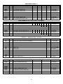
PROGRAMMING THE COMMUNICATOR
PAGES 8 & 9 DESCRIBE ALL THE LOCATIONS WHICH MUST BE PROGRAMMED IN ORDER FOR
THE RANGER 7600 TO FUNCTION AND REPORT TO A CENTRAL STATION. OTHER OPTIONS
MAY BE SELECTED BY FOLLOWING THE ADDITIONAL PROGRAMMING INSTRUCTIONS.
LOCATIONS 032-047: PROGRAMMING THE PRIMARY TELEPHONE NUMBER
The primary telephone number is programmed in successive locations beginning with location 032. Any zero (0)
within the telephone number, must be programmed as a "10".Programming a "0" will indicate the end of the phone
number. Four second delays can be programmed at any point in the phone number by programming a "13" in the
location where a delay is desired. If a "r" or "#" are required in the phone number, an "11" = "r" and "12" = "#". If
tone dialing is desired, program a "15" in the location where tone dialing should begin. If the entire number should
be tone dialing, program a "15" in location 032.
LOCATIONS 048-051: PROGRAMMING THE ACCOUNT CODE FOR THE PRIMARY PHONE NUMBER
The account code sent when the PRIMARY phone number is dialed is programmed in locations 048-051. Any zero
(0) within the account code must be programmed as a "10", and the communicator will report a zero (0). If the
account code is three digits long, use locations 048, 049, and 050. Program a "0" to indicate the end of the account
code.
LOCATION 052: PROGRAMMING COMMUNICATOR FORMAT FOR THE PRIMARY PHONE NUMBER
Location 052 contains the communicator format used to transmit to the receiver connected to the primary phone
number. Consult the instructions for your central station receiver to determine which format is compatible. To
select Universal 4 + 2, program a "1" in location 052. Contact ID requires a "13" in this location. If you need
another format, choose from those listed in the format table located on the following page, and program the data
in location 052. If this location contains a "0", the built-in communicator will be disabled, and the Ranger 7600 will
function as a local only control.
LOCATION 053: SECONDARY TELEPHONE NUMBER SEQUENCE CONTROL
Location 53 is used to control the secondary telephone number. If location 53 contains a" "0 the secondary phone
number is used as a backup to the primary number. Programming a "1" in location 53 will cause the secondary
number to be used only with dual and split reporting (no backup reporting enabled). Programming a "3" in location
53 will cause the control to alternate between the primary and secondary number (2 calls each) for the number of
attempts programmed in location 134.
LOCATIONS 054-069: PROGRAMMING THE SECONDARY TELEPHONE NUMBER
Locations 054-069 contain the secondary telephone number. This number allows certain communicator reports to
go to another number, or to cause the communicator to dial a second number if the primary number does not
respond after the number of attempts programmed into location 134 have been tried unsuccessfully. The same
number of attempts are made with the back-up number. Tone dialing and delay instructions are the same as for the
primary number.
LOCATIONS 070-073: PROGRAMMING THE ACCOUNT CODE FOR THE SECONDARY PHONE NUMBER
The account code sent when the Secondary phone number is dialed is programmed in locations 070-073. Any
zero (0) within the account code must be programmed as a "10", and the communicator will report a zero (0). If
the account code is three digits long, use locations 070, 071, and 072. Program a "0" to indicate the end of the
account code.

9
LOCATION 074: PROGRAMMING COMMUNICATOR FORMAT FOR THE SECONDARY TELEPHONE NUMBER
Location 074 contains the communicator format for the secondary phone number. Consult the instructions for your
central station receiver to determine which format is compatible. To select Ademco/Silent Knight Fast, program
a "2" in this location. Sescoa/Franklin Fast requires a"4" in this location, and Radionics 1800HZ/2300HZ Fast with
Parity and Hex Capability requires a "9" in this location. For a Pager format, program a "15" in this location, along
with the appropriate data in locations 208 and 209. If you need another format, choose from those listed in the
format table below, and program the appropriate data in this location. If location 074 is "0", the format programmed
in location 052 will be used.
COMMUNICATOR TABLE
DATA FORMAT DESCRIPTION
"0" LOCAL ONLY THE COMMUNICATOR IS DISABLED
"1" UNIVERSAL 4 + 2 1800HZ TRANSMIT 2300HZ HANDSHAKE DOUBLE
ROUND PARITY 40 PPS.
"2" ADEMCO/SILENT KNIGHT FAST 1900HZ TRANSMIT 1400HZ HANDSHAKE DOUBLE
ROUND PARITY 20 PPS.
"3" CADDX MODEM PROPRIETARY
"4" SESCOA / FRANKLIN FAST 1800HZ TRANSMIT 2300HZ 20PPS
"5" EXTENDED RADIONICS SLOW 1800HZ TRANSMIT 2300HZ HANDSHAKE DOUBLE
ROUND PARITY 20 PPS EXTENDED HEX CAPABILITY
"6" EXTENDED RADIONICS SLOW 1800HZ TRANSMIT 1400HZ HANDSHAKE DOUBLE
ROUND PARITY 20 PPS EXTENDED HEX CAPABILITY
"7" EXTENDED RADIONICS FAST 1800HZ TRANSMIT 2300HZ HANDSHAKE DOUBLE
ROUND PARITY 40 PPS EXTENDED HEX CAPABILITY
"8" EXTENDED RADIONICS FAST 1800HZ TRANSMIT 1400HZ HANDSHAKE DOUBLE
ROUND PARITY 40 PPS EXTENDED HEX CAPABILITY
"9" EXTENDED RADIONICS FAST
WITH PARITY
1800HZ TRANSMIT 2300HZ HANDSHAKE SINGLE
ROUND W/PARITY 40 PPS EXTENDED HEX
CAPABILITY
A= "10" EXTENDED RADIONICS FAST
WITH PARITY
1800HZ TRANSMIT 1400HZ HANDSHAKE SINGLE
ROUND W/PARITY 40 PPS EXTENDED HEX
CAPABILITY
B= "11" ADEMCO 4 + 2 EXPRESS DTMF
C= "12" SILENT KNIGHT 4 + 2 1900HZ TRANSMIT 1400 HANDSHAKE DOUBLE
ROUND 20PPS
D= "13" ADEMCO CONTACT ID DTMF (SEE APPENDIX 2)
E= "14" SIA FSK (SEE APPENDIX 1)
F= "15" PAGER/CUSTOM FORMAT SEE OVER-RIDE LOCATIONS 182, 183, 208, 209.
When using the 4+2 format, you must program the Alarm Code in reverse. The Zone number will go in the
first Location, and the event will be the second Location.
Example: To send a code 31 for Zone 1 program “1" in location 104 and program “3" in location 105. The
central station will receive the code 31.

10
LOCATIONS 000-003: PROGRAMMING THE MASTER ARM/DISARM CODE
Locations 000-003 contain master arm/disarm code (user number 1). Location 000 contains the first digit of the
code; location 003 contains the fourth digit of the code. THE CODE MUST CONTAIN FOUR (4) DIGITS. The master
code can then be used in the run mode to enter arm/disarm codes 1-7. The factory default code is [1][2][3][4].
LOCATIONS 004-023: PROGRAMMING THE ARM/DISARM CODE FOR USERS 2 THRU 6
Locations 004-023 contain the arm/disarm codes for user numbers 2 thru 6. Location 004 contains the first digit of
the code #2, and location 007 contains the fourth digit of code #2. THESE CODES MUST CONTAIN FOUR (4)
DIGITS. To disable a code, PROGRAM a "15" as the first digit of the code. These codes can be changed in the RUN
mode using the master code. User codes 8 thru 14 (locations 212-239) can be accessed from the program mode
only.
LOCATIONS 024-027: PROGRAMMING THE DURESS CODE OR USER 7
Locations 024-027 contain the arm/disarm code for Duress or for user number 7. Duress capability is enabled by
programming a communicator code in locations 086-087. If locations 086-087 are left unprogrammed, user number
7 will act as a standard user code.
LOCATIONS 028-031: PROGRAMMING THE "GO TO PROGRAM" ACCESS CODE
Locations 028-031 contain the "Go To Program" access code. Location 028 contains the first digit of the code and
location 031 contains the fourth digit of the code. THE CODE MUST CONTAIN FOUR (4) DIGITS. With the Ranger
7600 disarmed, the "Go To Program" access code can be used to enter the program mode. To disable the "Go To
Program" access code, program a "15" in location 028. The factory default setting is [9][7][1][3].
LOCATIONS 032-074: SEE PAGES 8 & 9
LOCATION 075: PROGRAMMING THE ENTRY DELAY TIME
Location 075 contains the number of 10 second increments in the entry delay. The entry delay can be programmed
in 10 second increments from 10 to 150 seconds ("1" = 10 seconds through "15" = 150 seconds). For example,
programming a "2" in this location will produce an entry delay of 20 seconds. (Note: A "0" entry is treated as 0
seconds). Programming a "6" in this location will produce an entry delay of 60 seconds. Factory default is 30
seconds.
LOCATION 076: PROGRAMMING THE EXIT DELAY TIME
Location 076 contains the number of 10 second increments in the exit delay. The exit delay can be programmed in
10 second increments from 10 to 150 seconds ("1" = 10 seconds through "15" =150 seconds). For example,
programming a "2" in this location will produce an exit delay of 20 seconds. (Note: A "0" entry is treated as 0
seconds). Programming a "6" in this location will produce an exit delay of 60 seconds. Factory default is 60 seconds.
LOCATION 077: PROGRAMMING THE SIREN SHUTDOWN/RECYCLE TIMEOUT
Location 077 contains the number of 2 minute increments in the automatic cutoff time. The automatic cutoff time can
be programmed in 2 minute increments from 2 to 30 minutes ("1" = 2 min thru "15" = 30 min). For example,
programming a "2" in this location will produce an automatic cutoff time of 4 minutes. Programming a "6" in this
location will produce an automatic cutoff time of 12 minutes. Factory default is 8 minutes.

11
LOCATIONS 078-083: PROGRAMMING THE ZONE TYPES
Locations 078 through 083 contain a number identifying the characteristics of each of the 6 zones. Location 078
corresponds to zone 1 and location 083 corresponds to zone 6. Each zone will factory default according to the
programming worksheet. To program zone characteristics other than the default values, program a number from "1"
to "10" based on the characteristics in the list below. NOTE: Zones 5 and 6 cannot be Priority (FIRE) zones.
NUMBER ZONE CHARACTERISTICS DESCRIPTION
"1"
DAY ZONE - A trip on a Day zone will produce an instant alarm when armed, and activate the keypad
sounder when disarmed.
"2"
24 HOUR - A trip on a 24 Hour zone will produce an instant alarm when armed or disarmed.
"3"
ENTRY/EXIT - A trip will start entry delay. The lack of a trip during exit delay will enable the "Automatic
Bypass" or "Instant" mode if so programmed.
"4"
INTERIOR DELAY - A trip on Interior Delay zone will initiate an entry delay. It will be ignored during exit
delay and when disarmed .
"5"
INTERIOR FOLLOWER - Interior zone that follows delay zones. It can be bypassed before arming, or
automatically bypassed in the "Automatic Bypass/Instant" mode if so programmed. When bypassed, it can
be reactivated by entering first digit of User 1 code then pressing [r].
"6"
INSTANT - Produces an instant alarm when tripped in the armed mode, ignored when disarmed.
"7"
24 HOUR SILENT - A trip on a 24 hour silent zone will communicate to the central station when the Ranger
7600 is armed or disarmed.
"8"
PRIORITY - A short on a Priority zone (non-bypassable) will communicate to the central station when the
Ranger 7600 is armed or disarmed. An open will create a Trouble condition. Keypad LED will be steady
for FIRE, and flashing for Trouble. Only Zones 1-4 can be used as Priority.
“9"
SECONDARY DELAY - A secondary delay zone works like an entry/exit zone but has its own
independent delay time (see locations 178-179).
“10"
24 HOUR - A trip on a 24 Hour zone will produce a beeping keypad when armed or disarmed.
LOCATION 084: PROGRAMMING THE ZONE 1-4 SIREN SELECT
Location 84 is used to select the Siren for zones 1-4. Refer to the chart below to choose the zone(s) for siren
activation. Add the values of the zones selected and program the sum in location 084.
VALUE DESCRIPTION
1 Zone 1
2 Zone 2
4 Zone 3
8 Zone 4
Example: If zones 2 & 3 are to sound the siren for an alarm, program a "6". Factory default is “15", all zones initiate
a siren.
LOCATION 085: PROGRAMMING THE ZONE 5-6 SIREN SELECT
Location 85 is used to select the Siren for zones 5-6. Refer to the chart below to choose the zone(s) for siren
activation. Add the values of the zones selected and program the sum in location 085. Default is “3".
VALUE DESCRIPTION
1 Zone 5
2 Zone 6

12
!!!! IMPORTANT NOTE !!!!
WHEN PROGRAMMING THE FOLLOWING COMMUNICATOR CODES,
A "10" MUST BE PROGRAMMED IN ORDER TO REPORT A ZERO (0).
LOCATION 086-087: PROGRAMMING THE RANGER 7600 FOR DURESS CODE CAPABILITY
The Ranger 7600 has the ability to report a duress code when the system is armed or disarmed with user code
number 7 and a duress communicator code is programmed in locations 086-087. If both locations are "0", the duress
capability is disabled and user code number 7 can only be used as a standard arm/disarm code. Location 086
contains the standard digit, and location 087 contains the extended digit. When Contact ID is selected, program the
extended or the second location with the required event code from Appendix 2 to enable this report event.
LOCATION 088-089: PROGRAMMING FOR AUXILIARY 1, [1] & [3] DOUBLE KEYPRESS
The Ranger 7600 has the ability to report an Auxiliary 1 code and activate the Priority siren each time the [1] and
[3] keys are pressed simultaneously on the keypad. The desired reporting code is programmed in locations 088-089.
If both locations are "0", the Auxiliary 1 double keypress is disabled. Location 088 contains the standard digit, and
location 089 contains the extended digit. If activated, the siren can be silenced by entering any arm/disarm code.
When Contact ID is selected, program the extended or the second location with the required event code from
Appendix 2 to enable this report event.
LOCATION 090-091: PROGRAMMING FOR AUXILIARY 2, [4] & [6] DOUBLE KEYPRESS
The Ranger 7600 has the ability to report an Auxiliary 2 code and activate the pulsing buzzer each time the [4] and
[6] keys are pressed simultaneously on the keypad. The desired Auxiliary 2 code is programmed in locations
090-091. If both locations are "0", the Auxiliary 2 double keypress is disabled. Location 090 contains the standard
digit, and location 091 contains the extended digit. If activated, the keypad sounder can be silenced by entering any
Arm/Disarm code. When Contact ID is selected, program the extended or the second location with the required event
code from Appendix 2 to enable this report event.
LOCATION 092-093: PROGRAMMING FOR KEYPAD PANIC, [rr] & [#] DOUBLE KEYPRESS
The Ranger 7600 has the ability to report a Keypad panic code and activate the Burg siren each time the [r] and
[#] keys are pressed simultaneously on the keypad. The desired Keypad panic code is programmed in locations
092-093. If both locations are "0", the Keypad panic double keypress is disabled. Location 092 contains the standard
digit, and location 093 contains the extended digit. If activated, the siren can be silenced by entering any Arm/Disarm
code. (Can also be silent - see Loc. 129) When Contact ID is selected, program the extended or the second location
with the required event code from appendix 2 to enable this report event.
LOCATION 094-095: PROGRAMMING THE KEYPAD TAMPER FEATURE
The Ranger 7600 has an optional tamper feature that, when enabled, will lock out the keypads for 1 minute if 30
random keypresses are made without producing a valid code. The desired tamper code should be programmed in
locations 094-095. If the control is not programmed for local only, the tamper will be communicated. If both locations
are "0", the tamper feature will not be enabled or reported. Location 094 contains the standard digit, and location
095 contains the extended digit. When Contact ID is selected, program the extended or the second location with any
number to activate this report.

13
LOCATION 096-097: PROGRAMMING TO REPORT DOWNLOADING COMPLETE
Locations 096-097 contain the communicator codes sent each time a download session has been completed. The
report will come in after a disconnect has been made from a downloading session. Location 096 contains the
standard communicator code, and location 097 contains the extended communicator code. If locations 096-097 are
"0", this report is disabled. When Contact ID is selected, program the extended or the second location with any
number to activate.
LOCATION 098-099: PROGRAMMING FOR AUTOTEST REPORTS
The Ranger 7600 has the ability to send autotest reports at intervals from 1 to 15 days. Locations 098-099 contain
the communicator codes sent for autotest. Location 098 contains the standard communicator code, and location 099
contains the extended code. If locations 098-099 are "0", autotest is disabled. When Contact ID is selected, program
the extended, or second location with any number to activate.
(NOTE: WHEN USING AUTOTEST, LOCATIONS 152-166 MUST BE PROGRAMMED.)
LOCATION 100-101: PROGRAMMING THE 7600 TO REPORT FAIL TO COMMUNICATE
The 7600 has the ability to send a failure to communicate report each time communication is re-established after
a signal has been unable the report. The data that failed to communicate will not be sent but it can be recovered from
the log. The desired Fail to communicate code is programmed in locations 100-101. If both locations are "0", Fail
to Communicate will not be reported. Location 100 contains the standard digit, and location 101 contains the
extended digit. When Contact ID is selected, program the extended, or second location with any number to activate.
LOCATION 102: PROGRAMMING TO REPORT CLOSING
The Ranger 7600 has the ability to report a closing code each time the control is armed. Program the desired
closing-code in Location 102. If this location contains a "0", closing will not be reported. When using a one button
"Quick Arm" code or the Remote Arming input, the man number is 1. When using the Auto Arm feature, the man
number is 9. The closing report will not be initiated until the end of the exit delay. When Contact ID is selected,
program with any number to activate this report..
LOCATION 103: PROGRAMMING TO REPORT OPENINGS
The Ranger 7600 has the ability to report an opening code each time the control is disarmed. Program the desired
opening code in Location 103. If this location contains "0", openings will not be reported. When using the remote
arming input, the man number is 1. When Contact ID is selected, program with any number to activate this report..
LOCATION 104-105: PROGRAMMING THE COMMUNICATOR CODE FOR ZONE 1
Locations 104-105 contains the communicator code to be reported each time zone 1 creates an alarm. Location 104
contains the standard digit, and location 105 contains the extended digit. When using Contact ID format, the number
programmed in location 104 is sent as the Zone ID. On location 105 Refer to Appendix 2. If left unprogrammed, it
will follow the Zone type.
LOCATION 106-107: PROGRAMMING THE COMMUNICATOR CODE FOR ZONE 2
Locations 106-107 contain the communicator code to be reported each time zone 2 creates an alarm. Location 106
contains the standard digit, and location 107 contains the extended digit. When using the Contact ID format, the
number programmed in location 106 is sent as the Zone ID. On location 107 refer to Appendix 2. If left
unprogrammed, it will follow the Zone type.
LOCATION 108-109: PROGRAMMING THE COMMUNICATOR CODE FOR ZONE 3
Locations 108-109 contain the communicator code to be reported each time zone 3 creates an alarm. Location 108
contains the standard digit, and location 109 contains the extended digit. When using the Contact ID format, the
number programmed in location 108 is sent as the Zone ID. On location 109 refer to Appendix 2. If left
unprogrammed, it will follow the Zone type.

14
.LOCATION 110-111: PROGRAMMING THE COMMUNICATOR CODE FOR ZONE 4
Locations 110-111 contain the communicator code to be reported each time zone 4 creates an alarm. Location 110
contains the standard digit, and location 111 contains the extended digit. When using the Contact ID format, the
number programmed in location 110 is sent as the Zone ID. On location 111 refer to Appendix 2. If left
unprogrammed, it will follow the Zone type.
.
LOCATION 112-113: PROGRAMMING THE COMMUNICATOR CODE FOR ZONE 5
Locations 112-113 contain the communicator code to be reported each time zone 5 creates an alarm. Location 112
contains the standard digit, and location 113 contains the extended digit. When using the Contact ID format, the
number programmed in location 112 is sent as the Zone ID. On location 113 refer to Appendix 2. If left
unprogrammed, it will follow the Zone type.
LOCATION 114-115: PROGRAMMING THE COMMUNICATOR CODE FOR ZONE 6
Locations 114-115 contain the communicator code to be reported each time zone 6 creates an alarm. Location 114
contains the standard digit, and location 115 contains the extended digit. When using the Contact ID format, the
number programmed in location 114 is sent as the Zone ID. On location 115 refer to Appendix 2. If left
unprogrammed, it will follow the Zone type.
.
LOCATION 116-117: PROGRAMMING TO REPORT START OF TEST MODE
The Ranger 7600 has the ability to signal the central station that a test mode has begun. This test mode can be used
to alert the central station not to dispatch alarms sent during the test. The test mode is entered by pressing[r]-[9]-[0]-
[#] (followed by the master code). Locations 116-117 contain the communicator code sent when the control is in the
test mode. Location 116 contains the standard digit and location 117 contains the extended digit. When Contact ID
is selected, program the extended or the second location with any number to activate.
LOCATION 118-119: PROGRAMMING TO REPORT END OF TEST MODE
The 7600 has the ability to signal the central station that a test mode has ended. This test mode can be used to alert
the central station that the test mode has ended. The test mode is exited by pressing[r]-[9]-[0]-[#] (followed by the
master code). The test mode will automatically expire after 1 hour. Locations 118-119 contain the communicator
code sent when the control exits the test mode. Location 118 contains the standard digit and location 119 contains
the extended digit. When Contact ID is selected, program the extended or the second location with any number to
activate.
LOCATION 120-121: PROGRAMMING TO REPORT AC POWER LOSS
The Ranger 7600 has the ability to report an AC power failure code when AC power is lost. This report can be
immediate, or delayed depending on the information programmed in location 150 (AC POWER LOSS DELAY). The
desired AC failure mode should be programmed in locations 120-121. If both locations are "0", AC power failures
will not be reported. Location 120 contains the standard digit, and location 121 contains the extended digit. When
Contact ID is selected, program the extended or the second location with any number to activate this report.
LOCATION 122-123: PROGRAMMING TO REPORT LOW BATTERY
The Ranger 7600 has the ability to report a low battery code when AC power has been lost and the battery has
discharged down to 10.3 volts. The desired low battery code is programmed in locations 122-123. If both locations
are "0", low battery will not be reported. Location 122 contains the standard digit, and, location 123 contains the
extended digit. When Contact ID is selected, program the extended or the second location with any number to
activate this report.

15
LOCATION 124: PROGRAMMING FOR PRIORITY ZONE TROUBLE REPORTING
The Ranger 7600 has the ability to report a trouble code each time a Priority zone opens. The desired trouble code
is programmed in location 124. If this location contains a "0", the Priority Trouble will not be reported. When Contact
ID is selected, program the location with any number to activate this report.
LOCATION 125: PROGRAMMING FOR ZONE BYPASS REPORTING
The Ranger 7600 has the ability to report a bypass on zones 1-6. The desired bypass code is programmed in
location 125. If this location contains a "0", zone bypass will not be reported. The bypass will be reported at the end
of the exit delay for non-24 hour zones. 24 hour zones will report a bypass immediately. When a bypass is removed,
a restore will be reported if "Restore" is enabled in location 126. When Contact ID is selected, program with any
number to activate this report.
LOCATION 126: PROGRAMMING THE COMMUNICATOR CODE FOR RESTORAL
Location 126 contains the communicator code that will be sent for restoral of a zone. If this location contains a "0",
no restorals will be reported. If a restoral code is programmed and an extended format is selected, the restorals will
be reported by zone. If a restoral code is programmed and an extended format is not selected, a restoral code will
be sent when all of the previously reported conditions have restored. When Contact ID is selected, program with
any number to activate this report.
LOCATION 127: PROGRAMMING THE COMMUNICATOR CODE FOR CANCEL (EXCEPTION OPENING)
Location 127 contains the communicator code that will be sent for cancel. The cancel code programmed in this
location will be sent if an arm/disarm code is entered after a trip on zones 1 through 6 has been reported (excluding
24 hour zones). After a cancel has been reported, no loop restorals will be transmitted on non-24 Hour zones. If this
location contains a "0", cancel is disabled. When Contact ID is selected, program with any number to activate this
report.
LOCATION 128: PROGRAMMING ABORT DELAY BEFORE DIAL TIME
Location 128 is used to enable the communicator abort. The number programmed in location 128 is the number of
2 second increments the communicator will delay before dial of a burglary alarm. If an arm/disarm code is entered
during this delay the 7600 will abort the transmission. If this location contains a "0", the Ranger 7600 will not abort
any reports.
(24 hour Zone will not abort)
LOCATION 129: PROGRAMMING FOR SILENT PANIC/HOLD-UP
Location 129 is used to silence the audible output for a panic/hold-up alarm. Programming a "1" in this location will
silence the audible output during a panic/hold-up alarm. If this location contains a "0", the Ranger 7600 will have an
audible panic/hold-up output.
LOCATION 130: LIMITED SIREN AND/OR COMMUNICATOR OUTPUTS
Location 130 is used to limit the sirens or the communicator, or both, to one output per zone during a single arming
cycle. The following table will indicate the value to be programmed in location 130 to give the 7600 the desired
characteristics. Factory default is "0", unlimited siren, and unlimited reports for the communicator.
VALUE DESCRIPTION
0 SIRENS AND COMMUNICATOR NOT LIMITED
1 SIREN ONCE PER ZONE, COMMUNICATOR NOT LIMITED
2 COMMUNICATOR ONE REPORT PER ZONE, SIREN NOT LIMITED
3 SIREN AND COMMUNICATOR LIMITED TO ONCE PER ZONE

16
LOCATION 131: AUTOMATIC BYPASS / INSTANT ARMING
Location 131 is used to enable "Automatic Bypass/Instant Arming". Programming a "1" in this location will cause
the control to automatically enter the "Instant" mode and bypass interior follower zones if a fault is not detected on
an entry/exit zone during the exit delay. Programming a "3" in this location, will cause the interior follower zones to
become bypassed if a fault is not detected on an entry/exit zone, yet will not change the status of the entry/exit zone.
If this location contains a "0", these features are disabled. Pressing the [r] key when the system is armed, will cause
the "Instant" light to toggle. When the "Instant" light is on, the entry/exit zone is instant; when off, the entry/exit zone
is delayed. The [r] key will toggle the "Instant" mode regardless of the programming data in this location. When the
system is armed, bypassed interior follower zones can be reactivated by entering [first digit of master code] followed
by [r]. Once the interior is reactivated they cannot be bypassed again without disarming the control.
LOCATION 132: ENABLE KEYPAD SIREN SOUNDER
The built-in keypad siren of the 8001 is enabled in location 132 by programming a "1" in location 132 to enable.
LOCATION 133: L.E.D. EXTINGUISH FEATURE
Keypad LEDs (with the exception of the A.C. LED) will be extinguished after 60 seconds of keypad inactivity if a "1"
is programmed in location 133. The LEDs will become illuminated immediately upon a keypress or alarm condition.
LOCATION 134: ENTERING THE NUMBER OF DIAL ATTEMPTS
Location 134 is used to enter the number of dial attempts (1 to 15 attempts) the communicator will try for the
appropriate phone number(s) before ending the notification process. If this location contains an "8", the
communicator will make 8 attempts to the first number, and then eight attempts to a second number, if a second
number is programmed as backup.
LOCATION 135: POWER UP CONDITION
If a "1" is programmed in location 135, the Ranger 7600 will power-up disarmed if there is a total power shutdown
and battery failure. If a "2" is programmed in this location, it will power up armed. If this location contains a "0", the
Ranger 7600 will maintain the condition it was in at power down. A watchdog circuit reset will cause the Ranger 7600
to reset to the selected condition.
LOCATION 136: POWER UP DELAY
If a "1" is programmed in location 136, the Ranger 7600 will not delay 60 seconds before accepting open or short
inputs from any zone. If a "0" is programmed, sensors on all zones are allowed 60 seconds to stabilize at power-up,
or after exiting the program mode. After 60 seconds, the Ranger will once again accept loop opens or shorts as an
alarm condition. This 60 second period will also be initiated after a watchdog circuit reset condition.
LOCATION 137: IMMEDIATE RESTORE BY ZONE
If a "1" is programmed in location 137, restoral signals will follow the restore condition and report restores
immediately after the condition has unfaulted. A non-extended format will not send a restore message until all zones
and trouble conditions have restored. If this location contains a "0", the restore signal or signals will be reported only
after siren timeout.
LOCATION 138: NO ARMING WITH A ZONE BYPASSED
If a "1" is programmed in location 138, the Ranger 7600 will not arm with any zone bypassed.
LOCATION 139: ENABLING QUICK ARM
The Ranger 7600 can be programmed to "Quick Arm" with the 3 key by programming a "1" in location 139. A "0" in
this location will disable this feature. If the "Quick Arm" digit is the same as the first digit of the "Go To Program
Code", the "Quick Arm" code will not function.

17
LOCATION 140: PRIORITY SIREN CUTOFF INHIBIT
If a “1" is programmed in location 140, a Priority zone type siren will sound continuously until an arm/disarm code
is entered. If this location contains a “0", the Priority zone type siren will shutdown after the amount of time
programmed in location 077 has elapsed. Programming in this location does not affect the burglary siren.
LOCATION 141: PROGRAMMING LOCAL SYSTEM FUNCTIONS
Location 141 is used to enable the exit warning tone and the missing battery test. The exit warning tone sounds a
long beep followed by 3 short beeps, 10 seconds before the exit delay expires. To enable the exit warning, program
a "1" in location 141. Location 141 is also used to enable the missing battery test. When enabled this feature will
cause the system to test the standby battery once every 40 seconds to see if it is present. If it is not, a low battery
will be detected. To enable missing battery detection program a "2" in location 141. To enable both exit warning and
missing battery detection program a "3".
LOCATION 142: SIREN/BELL TEST FEATURE
The siren/bell can be programmed to activate upon different conditions. Using the chart below, add the values of
the desired condition(s) and program the sum of those values in location 142. When the siren/bell is activated by
pressing the [1] and [7] keys simultaneously, the communicator will not report a message, the siren/bell will be
activated and a 1 minute battery test will begin. The bell/siren can be silenced by entering an arm/disarm code.
VALUE DESCRIPTION
1 Activation by pressing [1] and [7] keys simultaneously
2 Momentary activation at arming
4 Momentary at end of exit delay
8 Momentary at kiss off ringback
LOCATION 143: SMOKE POWER RESET AND/OR FIRE ALARM VERIFICATION
Programming a "1" in location 143 will cause the 7600 (when in the disarmed state) to interrupt the smoke detector
power each time the [#] button is pressed. If this location contains a "0", the smoke detector power will reset only
after the [#] button is pressed when the corresponding LED(s) for zones designated as "Priority" are on steady for
alarm or blinking for trouble. Programming a "2" in this location will enable the "Fire Alarm Verification" feature. When
the "Fire Alarm Verification" feature is enabled, a smoke detector will be powered down and reset automatically after
the first trip, waiting for a second trip within a 2 minute time frame (thus verifying a fire alarm condition) before
creating an alarm and communicating a message.
LOCATION 144: RESERVED

18
LOCATION 145-148: PROGRAMMING THE AUXILIARY OUTPUT
The 7600 has one auxiliary output located on terminal 11 on the control PC board. This output can be activated by
four different conditions selected from the 16 options in the following table. To utilize this output, program locations
145-148 with a number from "0" to "15" in accordance with the desired characteristics listed below. The output will
trigger for any of the activations programmed in any of these locations.
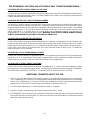
AUXILIARY OUTPUT TABLE
PROGRAM DIGIT ACTIVATION ON NOTES
“0" DISABLED DISABLED
“1" BURGLAR ALARM MOMENTARY OUTPUT
"2" FIRE ALARM MOMENTARY OUTPUT
"3" PANIC ALARM/DURESS MOMENTARY OUTPUT
"4" ARMED STATE LATCHED OUTPUT
"5" AC POWER LATCHED OUTPUT
"6" LOW BATTERY LATCHED OUTPUT
"7" LINE SEIZURE MOMENTARY OUTPUT
"8" TAMPER ALARM LATCHED OUTPUT
"9" AUTOTEST MOMENTARY OUTPUT
"10" RESERVED NOT USED
"11" ALARM MEMORY LATCHED OUTPUT
"12" ENTRY LATCHED OUTPUT
"13" EXIT LATCHED OUTPUT
"14" SMOKE DETECTOR POWER LATCHED OUTPUT
"15" GROUND START MOMENTARY OUTPUT
LOCATIONS 149: INVERTING THE AUXILIARY OUTPUT
The auxiliary output of the 7600 is normally POSITIVE (+) going NEGATIVE (-). It can be changed to a normally
NEGATIVE (-) going POSITIVE (+) by programming a 1 in location 149. {NOTE: CURRENT LIMITED TO 250
MICRO AMPS POSITIVE AND 20 mA NEGATIVE).
LOCATION 150: AC POWER LOSS DELAY FEATURE
Location 150 contains the number of 2 minute delays (2 to 30 minutes) the communicator will wait before reporting
an AC power failure. A "1" programmed in this location will create a two minute delay, and a "15" will create a 30
minute delay. If a "0" is programmed in this location, AC power failures will be reported WITHIN 30 SECONDS if AC
power loss reporting is enabled in locations 120-121.

19
LOCATION 151: PROGRAMMING THE NUMBER OF RINGS TO ANSWER DOWNLOAD CALL
Location 151 contains the number of rings the 7600 must detect before answering the telephone when initiating a
download. If a number from "1" to "15" is programmed in this location, the control will answer after THIS number of
rings has been detected. If a "0" is programmed in this location, the 7600 will not answer the download call.
LOCATION 152: PROGRAMMING THE NUMBER OF DAYS LEFT UNTIL AUTOTEST REPORT
Location 152 contains the number of days left until the next autotest report. If this location contains a "0", an autotest
signal will be reported the first time the current time equals the autotest time programmed in locations 162-165.
Locations 098-099 must be programmed to enable autotest reporting.
LOCATION 153: PROGRAMMING THE CLOCK, CURRENT MONTH
Location 153 contains the current month. The month must be programmed using a number from "1" to "12".
LOCATION 154: PROGRAMMING THE CLOCK, CURRENT YEAR - TENS DIGIT
Location 154 contains the current year - tens digit. If the current year is 1996, this location should contain a "9", which
is the tens digit of the current year.
LOCATION 155: PROGRAMMING THE CLOCK, CURRENT YEAR - ONES DIGIT
Location 155 contains the current year - ones digit. If the current year is 1996, this location should contain a "6",
which is the ones digit of the current year.
LOCATION 156: PROGRAMMING THE CLOCK, CURRENT DAY OF THE MONTH - TENS DIGIT
Location 156 contains the current day of the month - tens digit. If the current day of the month is the 5th (05), this
location should contain a "0", which is the current day of the month - tens digit. If the current day of the month is the
26th, this location should contain a "2".
LOCATION 157: PROGRAMMING THE CLOCK, CURRENT DAY OF THE MONTH - ONES DIGIT
Location 157 contains the current day of the month - ones digit. If the current day of the month is the 5th (05), this
location should contain a "5", which is the current day of the month - ones digit. If the current day of the month is the
26th, this location should contain a "6".
LOCATION 158: PROGRAMMING THE CLOCK, CURRENT HOUR - TENS DIGIT
Location 158 contains the current hour - tens digit. The time is entered in 24 hour time. If the current time is 5:25 PM,
the 24 hour time is 17:25, so this location should contain a "1", which is the current hour - tens digit. If the current
time is 9:36 AM, the 24 hour time is 09:36, so this location should contain a "0".
LOCATION 159: PROGRAMMING THE CLOCK, CURRENT HOUR - ONES DIGIT
Location 159 contains the current hour - ones digit. The time is entered in 24 hour time. If the current time is 5:25
PM, the 24 hour time is 17:25, so this location should contain a "7", which is the current hour - ones digit. If the
current time is 9:36 AM, the 24 hour time is 09:36, and this location should contain a "9".

20
LOCATION 160: PROGRAMMING THE CLOCK, CURRENT MINUTES - TENS DIGIT
Location 160 contains the current minutes - tens digit. The time is entered in 24 hour time. If the current time is 5:25
PM, the 24 hour time is 17:25, so location 160 should contain a "2", which is the current minutes - tens digit. If the
current time is 9:36 AM, the 24 hour time is 09:36, and this location should contain a "3".
LOCATION 161: PROGRAMMING THE CLOCK, CURRENT MINUTES - ONES DIGIT
Location 161 contains the current minutes - ones digit. The time is entered in 24 hour time. If the current time is 5:25
PM, the 24 hour time is 17:25, so this location should contain a "5", which is the current minutes - ones digit. If the
current time is 9:36 AM, the 24 hour time is 09:36, and this location should contain a "6".
LOCATION 162: PROGRAMMING THE AUTOTEST TIME, HOUR - TENS DIGIT
Location 162 contains the tens digit of the hour that the autotest report is initiated. The time is entered in 24 hour
time. If the desired autotest time is 5:25 PM, the 24 hour time is 17:25, so this location should contain a "1", which
is the tens digit of the desired hour for autotest. If the desired autotest time is 9:36 AM, the 24 hour time is 09:36,
and this location should contain a "0".
LOCATION 163: PROGRAMMING THE AUTOTEST TIME, HOUR - ONES DIGIT
Location 163 contains the ones digit of the hour that the autotest report is desired. The time is entered in 24 hour
time. If the desired autotest time is 5:25 PM, the 24 hour time is 17:25, so this location should contain a "7", which
is the ones digit of the hour for autotest. If the desired autotest time is 9:36 AM, the 24 hour time is 09:36, and this
location should contain a "9".
LOCATION 164: PROGRAMMING THE AUTOTEST TIME, MINUTES - TENS DIGIT
Location 164 contains the tens digit, of the minutes after the hour that the autotest is desired. The time is entered
in 24 hour time. If the desired autotest time is 5:25 PM, the 24 hour time is 17:25, so this location should contain a
"2", which is the tens digit of the minutes for autotest time. If the desired autotest time is 9:36 AM, the 24 hour time
is 09:36, this location should contain a "3".
LOCATION 165: PROGRAMMING THE AUTOTEST TIME, MINUTES - ONES DIGIT
Location 165 contains the ones digit, of the minutes after the hour that the autotest is desired. The time is entered
in 24 hour time. If the desired autotest time is 5:25 PM, the 24 hour time is 17:25, so this location should contain a
"5", which is the ones digit of the minutes for autotest time. If the desired autotest time is 9:36 AM, the 24 hour time
is 09:36, and this location should contain a "6".
LOCATION 166: PROGRAMMING THE AUTOTEST REPORTING INTERVALS
Location 166 contains the number of days between automatic test reports. If a report is desired every 7 days, this
location should contain a "7". Valid entries are "1" to "15" days.
LOCATION 167: PROGRAMMING USER 14 AS A SIREN SILENCE CODE
Programming an “8" in location 167 will cause the user 14 code to be a siren silence code. Entering this code when
the siren is on will cause the 7600 to silence the siren but will not change the armed state. Entering the code when
the siren is not on will restart the exit delay. When location 167 is programmed with an" 8", user 14 can never be
used to disarm the control. Programming a “4" in Location 167 is for 50Hz AC Supply.
LOCATION 168-175: RESERVED
Page is loading ...
Page is loading ...
Page is loading ...
Page is loading ...
Page is loading ...
Page is loading ...
Page is loading ...
Page is loading ...
Page is loading ...
Page is loading ...
Page is loading ...
Page is loading ...
Page is loading ...
Page is loading ...
Page is loading ...
Page is loading ...
Page is loading ...
Page is loading ...
-
 1
1
-
 2
2
-
 3
3
-
 4
4
-
 5
5
-
 6
6
-
 7
7
-
 8
8
-
 9
9
-
 10
10
-
 11
11
-
 12
12
-
 13
13
-
 14
14
-
 15
15
-
 16
16
-
 17
17
-
 18
18
-
 19
19
-
 20
20
-
 21
21
-
 22
22
-
 23
23
-
 24
24
-
 25
25
-
 26
26
-
 27
27
-
 28
28
-
 29
29
-
 30
30
-
 31
31
-
 32
32
-
 33
33
-
 34
34
-
 35
35
-
 36
36
-
 37
37
-
 38
38


CADDX RANGER 7600 Installation guide
- Category
- Security access control systems
- Type
- Installation guide
Ask a question and I''ll find the answer in the document
Finding information in a document is now easier with AI
Related papers


Other documents
-
Bull Power6 Troubleshooting guide
-
 GE Interlogix NetworX NX-8 Installation guide
-
Crow RUNNER Series User guide
-
Bulldog Security 727 Owner's manual
-
Micron Scorpion Z4120C Features & Operation
-
 Orbit Manufacturing RP-206 User manual
-
ADEMCO 4160-12 C-COM Installation Instructions Manual
-
Radionics D7024 Operating instructions
-
 AutoTest Euro Trailer Socket Tester User manual
-
GE NX-8V2 User manual


