ADEMCO 4160-12 C-COM Installation Instructions Manual
- Category
- Fire protection
- Type
- Installation Instructions Manual

.
@ IZ~PEMCOI
EXTENSIVELY REVISED! Margin Ilnes indicate ptlnclpal changes In this 6/67 Issue.
INDEX:
PAGE
General Information . . . . . . . . . . . . . . . . . . . . . . . . . . . . . . . . . . . . . . . . . . . . . .
1
1. Introduction.. . . . . . . . . . . . . . . . . . . . . . . . . . . . . . . . . . . . . . . . . . . . . . . . . .
1
A. System Characterrstics
. . , . . . . . . . . . . . . . . . . . . . . . . . . . . . . . . . . . 1.2
8. Zone Inputs . . . . . . . . . . . . . . . . . . . . .:. . . . . . . . . . . . . . . . . . . . . . . . . . .
2
C.SystemOptions............................................. 2
a Control Options . . . . . . . . . . . . . . . . . . . . . . . . . , . . . . . . . . . . . . . . , 2.3
l
Communicator Options.. . . . . . . . . . . . . . . . . . . . . . . . . . . . . . . . . . . .
3
II. Functtonal Descriptton
. . . . . . . . . . . . . . . . . . . . . . . . . . . . . . . . . . . . . . . . . 3
A. Functional Description, NO. 4160-12 C-COM.. . . . . . . . . . . . . . . . . . .
3
1. Switches
. . . . . . . . . . . . . . . . . . . . . . . . . . . . . . . . . . . . . . . . . . . . . . . . .
3
2. LED Indicators
. . . . . . . . . . . . . . . . . . . . . . . . . . . . . . . . . . . . . . . . . .
3.4
B. Functional Description, No. 4165 Siren Driver . . . . . . . . . . . . . . . . . . . 4
C. Functional Description, No. 5321 Security Console . . . . . . . . . . . . . . 4
1. Keypad. LEDs and Message Displays.. . . . . . . . . . . . . . . . . . . . . . .
4
2. Audible Signals . . . . . . . . . . . . . . . . . . . . . . . . . . . . . . . , . . . . . . . . . 4.5
D. Functional Description. No. 5314 Remote Keypad . . . . . . . . . . . . . . . 5
1. Keypad and LEDs . . . . . . . . . . . . . . . . . . . . . . . . . . . . . . . . . . . . . . . . .
5
2. Audible Signals . . . . . . . . . . . . . . . . . . . . . . . . . . . . . , . . . . . . . . . . . . .
5
E. Functional Description.
No. 9767/9789 Remote Key Arming Station.. . . . . . . . . . . . . . . . . . . . 5
III. Communtcator Operation. . . . . . . . . . . . .,.,...... . . . . . . . . . . . . . . . . .
5
A.LlneSeizure . . . . . . . . . . . . . . . . . . . . . . . . . . . . . . . . . . . . . . . . . . . . . . . .
5
B.Antr-Jam...........................;....................... 5
C. Dial Tone Detection . . . . . . . . . . . . . . . . . . . . . . . . . . . . . . . . . . . . . . . . .
5
D. PROM Calling Options . . . . . . . . , . . . . . . . . . . . . . . . . . . . . . . . . . . . . . .
6
E. Acknowledge Wait PROM Options.. . . . . . . . . . . . . . . . . . . . . . . . . . . .
6
F. Transmission Format PROM Options.. . . . . . . . . . . . . . . . . . . . . . , . , .
6
GENERAL INFORMATION:
No. 4160-l 2 Control/Communicator is a micrccomputer based product
which conveniently combines the control panel and digital communicator
into one package. This commercial-residential system provides every
important feature required for a UL certified household fire/burglary alarm
installation.
A typical system installation includes a No. 4160-12 C-COM. an optional
No. 4165 Plug-In Siren Driver, one or two No. 5321 Security Consoles.
optionally (up to four) No. 5314 Remote Keypads, and optionally (up to
four) No. 9787/9789 Remote Key Arming Stations.
lho No. 4160-12 C-COM monitors all inputs and generates appropriate
output signals for interior and exterior audible warning as well as for
remote communication to a central alarm monitoring service.
ma No. 4166 Slren Drlvar is an optional plug-in modute that provides the
capability to drive an 6 ohm siren speaker with up to 25 watts of sound
power with separate sound outputs for fife and burgtarylemergency. In
addition, two saparate fonat pair combinations are programmable for this
driver.
The (optional) No. 6321 Sacurlty ConsoIe(8) provide full system and
individual zone status indication as well as system control. With the NO.
5321, the system may be completely armed or just perimeter armed or
disarmed. The entry delay may be tumed off, zones may be shunted. and
user security codes may be changed. Threa typas of emergency alarms
may be triggered (fire, silent or audible potica atam?. and optional audible
emergency). A b&in speaker provides audible alarm. trouble. and
annunciator functions. The keypad is illuminated for nighttime
convenience.
lho (optIonal) No.
5214 Rmoto Keypad(8) pamit most of the keypad
functions of the No. 5321 tc be pertormed except for the panic atarm
triggers, as well as providing limited diiptay and audible annunciation for
modes, trouble. atarms, and shunts.
The (opuond) No. S7S7/97SB Ronwe Kmy Arming St&Ions permit
remote complete (AWAY) arming and disarming of the system as welt as
providing arming/disarming status indication. The system may also be
force armed from these locations it one or more zones are fauttad.
G. Message Verification PROM Options.. . . . . . . . . . . . . . . . . . . . . . . . . 6
H. Ademco Low Speed Reporting Format . . . . . . . . . . . . . . . . . . . . . . . . 6
I. Ademco High Speed Reportmg Format . . . . . . . . . . . . . . . . . . . . . . 6. 7
J. SESCOA/Radionics Reporting Formats . . . . . . . . . . . . . . . . . . . . . . . 8
IV. Installer PROM Programming . . . . . . . . . . . . . . . . . . . . . . . . . . . . . . . . . . .
8
A. Control PROM . . . . . . . . . . . . . . . . . . . . . . . . . . . . . . . . . . . . . . . . . . . 8-l 0
8. Communicalion PROM.. . . . . . . . . . . . . . . . . . . . . . . . . . . . . . . . . . 1 O-l 4
V. Installation and Wiring.. . . . . . . . . . . . . . . . . . . . . . . . . . . . . . . . . . . . . . . .
14
A. Installation and WinnQ. No. 4160-12 C-COM . . . . . . . . . . . . . . . . . . . 14
l.Termmals . . . . . . . . . :. . . . . . . . . . . . . . . . . . . . . . . . . . . . . . . . . . 14-16
2. Additional Connection Posts
. . . . . . . . . . . . . . . . . . . . . . . . . . . . . . . 16
B. Installabon. No. 4165 Siren Driver . . . . . . . . . . . . . . . . . . . . . . . . . . . . 16
C. Installation and Wiring. No. 5321 Security Console(s) . . . . . . . . 16. 17
0. lnstallabon and Wiring, No. 5314 Remote Keypad(s) . . . . . . . . . . . . 17
Vi. System Checkout.. . . . . . . . . . . . . . . . . . . . . . . . . . . . . . . . . . . . . . . . 16.19
VII. Operation . . . . . . . . . . . . . . . . . . . . . . . . . . . . . . . . . . . . . . . . . . . . . . . 19.20
VIII. Turning The System Over to User . . . . . . . . . . . . . . . . . . . . . . . . . . . . . 20
IX. General Specifications . . . . . , . . . . . . . . . . . . . . . . . . . . . . . . . . . . . . 20.21
Diagram 1: Siren Speaker Configurations . . . . . . . . . . . . . . . . . . . . . , . . . . .
16
Diagram 2: Console Connections
. . . . . . . . . . . . . . . . . . . . . . . . . . . . . . . . . .
17
Diagram 3: Keypad Connections . . . . . . . . . . . . . . . . . . . . . . . . . . . . . . . . . .
16
Oiagram 4: No. 4160-12 Control/Communicator.. . . . . . . . . . . . . . . . . . . . 21
Diagram 5: No. 4165 Siren Driver.. . . . . . . . . . . . . . . . . . . . . . . . . . . . . . . . . 21
Diagram 6: No. 5321 Security Console . , . . . . . . . . . . . . . . . . . . . . . . . . . . . 22
Diagram 7: No. 5314 Remote Digital Keypad . , . . _ , . . . . . . . . . . . . . . . . . . 22
Diagram 8: No. 9787/g Keyswltch Arming Station . . . . . . . . . . . . . . . . . . . 22
Diagram 9: Summary of ConnectIons . . . . . . . . . . . . . . . . . . . . . . . . . . . . . .
23
I. INTRODUCTION
A SYS7EY CHARAClERlSTlCS
1. Six independent zones which may be configured in a variety of
ways.
2. Up to five burglaty zones (including one day trouble zone), two
panic zones. and one fire zone.
3. Console digital numeric display of the zone identification for alarms.
alarm memory, and trouble conditions.
4. Eight Keypad arm/disarm codes: one master code (PROM
selectable) and seven secondary codes (user changeable trom
keypad) each uniquely reported lo central station with open/close
reports.
5. Individual Zone bypass from the keypad.
6. Chime mode, duress code, forced arming - additional keypad
functions.
7. PROM variable entry/exit and alan sounder activation delay. alarm
sounder timeout, and delayed AC supervision reporting.
8. Alarm Relay and optional Plug-in siren driver outputs for audible
alarms.
9. Am\ing status output with programmable polarity for controt of
motion detectors.
10. Zone LEDs at the C-COM to indicate (he status of each zone.
11. AC Power LEt% at the C-COM and Security Console to indicate
that AC power is availabte and the battery is being charged.
12. Fire Test Switch to check the fire system functions.
13. Mu&-format communicator (Ademco Low Speed, Ademco High
Speed. SESCOA. Radionics. Radionics Superfast and Radionics
“BFSK”).
14. Touchtone or pulse dial call placement.
f 5. Touchtone or pulse tone data transmission.
16. Dual phone number calling with separate independent subscriber
IO.
17. Double transmission verification or single transmission with check
sum verification.

.
16. All reporting by zone for alarms, troubles. restores. shunts.
19. Low battery and AC power fail reporting.
20. Interface to serial data version (No. 76ZOSE) of Ademco 900 MHz
Long Range Radio Transmttter.
6. ZONE tNPUlS
1. Zones l-3: Burglary
Zone 1 and 2: Instant or Entry/Exit Delay - PROM selacta~e
zone 3:
tntenor with or without EntrylExft delay - PROM
salactable
2. Zone 4: Fire. Day Trouble/Night Alarm Instant Burglary, or
Standard Instant Burglary - PROM selectable
3. Zone 5: Police Panic (Audible or Silent) - PROM
seiectabie
4. tons 6:
Instant Burglary or Audible Emergency Panic - PROM
setectable.
C. SYSTEM OPTIONS
The system can be configured in a number of ways. This allows the
user to customize the system for his own particular needs. Before
actually making the choices which affect how the system operates
(see Section IV. INSTALLER PROM PROGRAMMING), it is important
to understand the options. The discussion that follows broadly divides
those options into two categories: control options andcommunicator
options.
pntrol Odfonaz
1:Entry ‘hay, Eatt Dalay
The entry delay is the time between entering the premises and when
the system must be disarmed to avoid activating an alarm. The exit
delay is the time between arming the system and when the premises
must be exited to avoid activating an alarm. The entry and exit delays
may be independently PROM setected to be between 0 and 135
seconds in 15 second increments.
NOTE: 60 seconds is the maximum exit delay and 45 seconds is the
maximum entry delay allowed in a Listed U.L. household
burglary installation by U.L. Standard 1023.
2ExtehrSoundartprtmaryCanmunk8torDatay
The system may be set up to delay the activation of the exterior bell
and/or siren (optional plug-in 4165 siren driver module required) and
the triggering of the communicator. This feature may be used to
reduce false alarms due to operator errors. The delay may be set in
PROM between 0 and 135 seconds in 15 second increments, but
applies only to those zones that have the delay feature enabled (see
No. 15). See Communicator Option tf2 for delay just to the communi-
cator triggering.
h~klmbnnwout
Bell/Siren audiile indication may be PROM selected to last between 0
and 36 minutes in 4 minute increments, after which it “times out”.
Indefinite sounding may also be PROM sefected for zone 4.
NOTE: 4 minutes is the minimum timeout allowed in a Listed U.L.
household instaltatii tor bu@aty sounding (per U.L. Stan-
dard 1023). Ftra sounding shall be present until the system is
reset (per U.L. Standard 865).
4.AcPowwLonnmor
To ekminate nuisance power failure central station and local audible
reports. the system may be PROM programmed to ignore short
duration outages. This delay in reporting an AC loss condition may be
set between 0 and 36 minutes in 4 minute increments (As an example,
if a timeout period ot 16 minutes was selected. power outages of less
than 16 minutes will be ignored - the POWER LED will extinguish
immediately. however). -
s.Entry/Exttzonesobctkm
The avstem altows a choice of zones that may be set up with
-,
entry/exit delay. Zones 1.2, and 3. individually or in any combination,
may be set
UD
in PROM as entry/exit zones (For exampte. tf the inte-
riorzone were set up with space protection, choosing an entry/exit
delay on this zone would allow space protection devices to include the
entry door in their area of protection which is to say, they could be
held off during the normal entry/exit period).
6.F~RWPOltMZOttOSOhdh
Fast (15 msec) reswnse
is used for certain devices (such as glass
break detectors and some photoetectrics) that cannot be used with a
normal (250 maec) response zone. Fast response can be PROM
designated for zones 2; 3 and 4. individually or in any combination.
7.Zone4fypaSdwUon
As shipped, zone 4 is configured as a standard burglary zone. How-
ever, it can also be configured in PROM as either a fully supervised
.
fire zone or a day/night burglary zone (during disarmed period. a trou-
Me indication is communicated and audibly sounded ff the loop iS
opened or shorted; a burglary alarm is triggered if the loop iS opened
or shorted during amred period).
8.2oneSond6Optlons
As shipped. zone 5 is configured as a silent panic zone. zone 6 as a
burglary zone. Optionally, zone 5 and/or 6 may be configdred in
PROM as audible panic zones. In addition, if zone 5 is set up as a
Silent Panic Zone, console display of both the panic condition as well
as the activity of the communicator may be inhibiied. (For example. if
zone 5 is set up as a silent personal emergency zone, the user would
want an indication that the alarm has been
trlQQered.
however. 11 zone 5
is intended for hold-up use, the display would not be desirable).
0. Ytacdfaneoua PROM Salectabk Control Options
a. Altemate Siren Soundaz
As shipped, the system will give the following sounds: Steady rapid
two-tone (Electronic bell) for Burglary/Panic; interrupted rapid two-
tone for fire. Optionally, steady slow two-tone for Burglary/Panic
may be PROM selected.
b. Atarm Sounder ‘Ding” Contlmutlon ot Arming:
When PROM selected, this option will cause a K second “Ding” of
the exterior bell and/or siren at the end of the arming sequence. If
me communicator has been set up to send opening and clostng
repot%. the “Ding” will occur when the communicator has received
a kissoff on a closing report. If opening/closing reports are not
used. the “Ding” will occur when the exit delay period has expired.
c Armlng Status Polarity:
The system has an output at TBl -1 that may be used to indicate
the arm/disarm status of the system to other devices (for example,
space protection). As shipped, the system will give the following
output:
+12 volts when armed,
0 volts when disarmed
Optionally, the polarity can be PROM reversed to give:
0 vats when armed,
Suitable for Ademco 12 voft and
+12 volts when disarmed.
AC powered space protection
devices.
10. Dwaaa Dlglt
The duress digit is an increase of 1 to the last digit of the security
code. Its purpose is to allow someone to initiate a silent panic
condition but still give the impression that the control is working
normally. For example, if the security code is 1234. the duress digit is
5. Entering 1234 + OFF wrll cause the system to disarm, but entering
1235 + OFF (assuming one is in a hostage situation) will cause the
system to disarm and also trigger the communicator to send a silent
panic message.
NOTES: 1. If the last digit of the security code is 9. there is no
duress capability for that code.
2. The user must make certain to avoid assigning
secondary codes that could be equivalent to another code
(secondary or master) modified by its duress digit so as to
not
transmit false alarms to the central monitoring service.
A simple caution to the user is to always have at least a
numeric diierence of 2 between security codes used.
11. Sacurlty coda
This 4 digit cede restricts the use of the system to only those who
know the code. Any digits. including repetitions, may be chosen.
There are eight such codes. One (master code) is PROM pro-
. grammed at rnstallatton and seven others (secondary codes) are user
changeable from a keypad at any time,
USI~Q
the master code to
enable the change.
12 Feraed Annhg Enabta
Forced arming allows a user to arm the system even though certain
zones are in a taulted condition. Such faulted zones will be shunted
by depressing BYPASS to override fail safe arming during arming.
Forced arming must be PROM enabled for each zone in which it is
desired (with critical zones. such as sates for instance, arming of the
system should be prevented when a faulted condition exists).
13. Bypaaa Enabte
Zones in the system may be individually bypassed from the Security
Console or Remote Keypad dunng the drsarmed or armed period.
This option allows the user to bypass zones that should be ignored.
whether or not they are faulted at arming time (In this manner,
“Swingers” may be ignored or a loading dock door that must be later
opened can be left unsecured). To allow individual zone bypass, each
such zone must be PROM enabled for this option.
2

14. Zone Restore Enable
As shipped. the system has all zones set up as non-restore zones.
Non-restore means that once a zone has gone into alarm during the
armed period, subsequent faults of that zone will not trigger a new
ahrm. The zone is effectively “locked-out”, preventing multiple false
alarms in the event of a “Swinger”.
Zones that have been PROM selected as restore zones will allow the
bell/siren to sound more than once if the zone returns to normal and
faults again after the bell/siren has timed out.
15. Alarm Sounder/Primary Communlutor Dohy Enable
1.
The “Exterior Sounder/f&&y Communicator belay” was explained
as option #2. above. PROM option 15 is simply the choice of burglary
zones for which exterior sounder and primary communicator delay IS
desired. It should be noted thal the delay does not apply to zone 4 if it
is set up as a fire zone nor to zones 5 or 6 if set up as panic.
Communicator Options:
Communicator Enabler
The system may be PROM programmed to transmit any combination
of the followtng messages:
a open/claw tIepotts
A closing report, if enabled, will be sent whenever the system is put
in the AWAY mode. The STAY mode will not generate a closing
report.
b. Zone Shunt Reporb
If PROM enabled, the system will report all shunted zones to the
central statron. These shunt reports will take place at the following
times.
1) Whenever a 24 hour zone (fire, panic, etc.) is shunted.
2) Burglary zones will report Shunting at the time of arming.
3) When the zone shunt is removed, a shunt restore message will
be sent for 24 hour zones (burglary zones will not send shunt
restore reports as an open repot-l automatically signifies shunt
restore for these zones).
c. ZOM 4 Trouble Reports
The system will transmit a trouble report. if PROM enabled.
whenever a trouble condition is sensed in zone 4. When the trouble
condition has restored for 16 seconds, a restore message will be
sent (if PROM enabled).
d. Cancel Code
If PROM enabled, the cancel code may be used for systems not
utilizing opening/closing reports. The cancel code will be sent if a
bUrQla~
alarm is turned off (cancelled) betore the bell/siren times
out. The cancel code does not apply for fire or panic reports.
however.
- 16Second
Sewnduy Conununkator Delay
An additional 16 second delay may be added 10 the communicator
trigger to reduce the possibility of false alarms. This timing begins
after any delay already provided by the Exterior Sounder/Primary
Communicator Delay optii (described above). The trigger detay
option might be chosen, for example. on zones not utiliiing the exte-
rior sounder delay. In addition to zones l-6, trigger delays are
available for both trouble and closing reports.
3. Report to Secondary phone Number Only
The system allows for the various communicator reports to be divided
between two central stations (or two receivers). This option is chosen
in some situations. where. for example. all alarms may be routed to a
primary alarm receiver while non-critical items, such as troubles or
open and closing reports, might be routed to a secondary receiver.
4. YlueUaneous Communlwtor OptMu.
rAllMws86osOnOneCall
As shipped. the system is set up with a feature that gives alarm
messages priority over trouble messages and other non-alarm
messages. when sending in a format other than Ademco High Speed.
For example. if an alarm message tor the primary receiver occurs
while the communicator is reporting shunt conditions to the secon-
dary receiver, the communicator will abort the shunt reports.
It will then call the primary receiver to report an alarm. After the
alarm has been reported. the commumcator will resume reporting
the shunts.
Optionally. the system may be made to finish all messages to the
active phone number before switching to the other phone number.
b. Duress Mewage to Second Phone Number
When PROM selected. this option routes duress messages to the
secondary receiver.
o. AC Fait/last/Low Battery to Sooond Phone Number
When PROM selected, this option routes AC Failure and
Restore, Low Battery. and Test reports to the secondary receiver.
d. Low Battery Report Format Select
.
AS shipped. when using Ademco High Speed Format. the System
will report Low Battery messages as follows:
ACCT 5555 5555 6 Low Banery
A PROM option is available that enables battery failure reporting In
a different manner (See Section on Hiah Speed Format). This for-
mat also allows battery restore reportsto 6e transmit@&
l
. Dual Report
When PROM selected, this option causes all communicator mes-
sages to be sent to both a primary receiver and a secondary
receiver.
1. ALT by 2’s (Alternate by Pairs)
This option, when PROM selected, will cause the communicator to
alternate between the primary receiver and the secondary receiver
while it is attempting to get through. It will first make two attempts to
the primary receiver, then two attempts to the secondary receiver,
and so on until it either receives a kissofi signal from one receiver
or exhausts the niaximum number of attempts.
5. Central Statton Restore Repoti Enable
If a zone is set up as a restore zone (see control option t14) and
it is desired to communicate restore, the reporting can be PROM
enabled for any such zone or zones.
6. Communlc8tor Channel Aulgnment
On the system, each alarm zone, as wetI as the duress report. may be
assigned a communicator channel. How the zones are assigned to
channels affects the tvoes of rewrts that will be sent. As an example,
each zone could be gl’;en a different communicator code for unique
zone reporting. Or the zones could be grOUped by function with
duress and silent panic zones as Channel for Code) 1. the fire zone
as Channel (or Cdde) 2. and the burglary z&es as~i=hannel (or Code)
3 (this would allow the system to be compatible with an existing
central station alarm code scheme).
7. Communltrtor Format
Individually selectable for primary and secondary telephone numbers-
Ademco Low Speed and/or Ademco High Speed, SESCOA.
Radionics. Radionics Superfast. and Radionics “BFSK’:
5. Long Range Radio
See instructions accompanying No. 7621SE for all PROM
PROGRAMMING OPTIONS. the most slonificant of which is the
selection of which reports will and will not be transmitted via Long
Range Radio.
3
II. FUNCTIONAL DESCRIPTION
A. FUNCTIONAL DESCRIPTION, NO. H66-12 C-COY (See
Dkgmm 4).
1. swtlchwz
FIRE TEST/RESET Swltchz Rightward movement of this
momentary action. center off switch shorts the fire loon to
initiate an glarm. causing the alarm sounder to a&a& In
addition. the Charging current to the battery is interrupted while
lhis switch is held, giving an indication of battery condition. The
test is reported to the central station using the Test code. The fire
test is reset by Sliding the switch to the RESET position.
Leftward movement of this switch resets the fire circuit. In
addition, the power to the smoke detectors is interrupted
resetting any detectors that were activated. Clearino of the
fire alarm memory indication on the console and on-the
C-COM requires entry of the security code and OFF at a console
or keypad.
In addition. the ftre circuit may be bypassed (if PROM selected) by
holding the switch to the left for 5 seconds. A fire trouble indica-
tion will be prowded when the fire circuit is bypassed.
Z LED lndlcators:
ZONE LEDS FOR ZONES 1.2,3,4,6 (RED): These LEDs indicate
the status of their respective zones:
ON STEADY - Existing Zone Fault
SLOWLY FLASHING - Shunted
RAPIDLY FLASHlNG - Memory of Alarm
ZONE 4 TROUBLE LED (RED): This LED indicates the trouble
status of zone 4 whether it is operating as a supervised fire zone or as
a day trouble burglary zone:
ON STEADY - Existing Trouble
RAPIDLY FLASHING - Memory of Trouble

POWER LED (GREEN): This LED indicates the presence of AC
power to operate the system. This LED will turn off immediately when
AC power is k?st.
B. FUNCTIONAL DESCRIPTlON, NO. 616S $lRENtDRlVM (&e
-5)
cell*
PITCH ADJUSYMENY: The small potentiometer permits the adjust-
ment of the pitch of sound produced by the siren driver. Clockwise
adjustment (as viewed from the right side of the cabinet) increases the
pitch and counterclockwise adjustment decreases the pitch.
C. FUNCflONAL DESCRIPTION, NO. S32l SECURlTY CONSOLE
(6.e Dironm 6)
1. Koy~ad, LEDs and Youage Dl8@ayc
NOTE: The interval between consecutive key depressions must
not
be greater than 2
seconds
for acceptance of the entry.
Keys 09: These are used to enter the security code and the
duress digit.
OFF Kay and LED (arun): When depressed subsequent to entry
of the security code, silences alarms, memory and trouble audibles
and disarms the system. The Off LED is lii when the system’s
burglary protection is turned off.
AWAY Kay and LED (Rod): When depressed subsequent to entry
of the security code, arms the entire burglary system ff there are no
faulted zones. The AWAY LED is lif when the system is armed in
thismode.
STAY Kay and LED (Rad): When depressed subsequent to entry
Of the security code. arms all of the burglary zones except Zone 3
(Interior Protection) if there are no faulted zones (other than Zone
3). The STAY LED is lii when the system is armed fn this mode.
POWER LED @run): This LED indicates the presence of AC
power to operate the system. This LED will turn off immediately
when AC power is lost.
BWASS
KEY and LED (Yeltow): When depressed subsequent to
entry of the security code and tollowed by one or more zone
number(s) (1 to 6) while in the armed or disarmed state, will individ-
ually shunt the zone(s) designated [assuming that the program-
ming ot the system permits the shunting of the particular zone(s)].
When depressed subsequent to entry of the security code and
either the AWAY or STAY keys, the burglary system will arm with
any taufted zones Shunted [assuming that the programming of the
system permits the torced automatic shunting of the particular
ZO~S)l.
The BYPASS LED is lii when one or more zones are shunted either
by force arming or by individual shunt selection. All shunts are
automatically removed when the system is turned off.
INSTANT Kay and LED (Yellow): When depressed subsequent to
entry of the security code and either the AWAY or STAY keys, the
burglary system will arm with the entry delay died on any zones
designated as entry/exit zones, making them instant alarm zones
tar subsequent entry. The INSTANT LED is lii when the system is in
thii mode. The entry delay tor these zones is restored subsequent
to the system be@ turned off.
CODE Kay and LED (Yellow): When depressed subsequent to
entry of the master security code, will permit the entry of a second-
ary code designator (2-6) tollowed by a user changeable 4 digit
secondary security code. A secondary code permits the peftor-
mance of all of the functions permitted by the PROM programmed
master code except change of it&f or other secondary codes to a
new code. ln addition, a secondary code can be blocked from
performance of any of its functions when the system is armed with
me master code. as an added security feature (if so programmed).
Repeating digits are permitted in code entries. ff a SecondarY code
entered happens to be similar to the master code (or another
secondary code) except for the lest digit being 1 hlghw, the duress
silent panic capability will be triggemd. causing a needless w
drnrr to be reported to the central alarm monitoring service. The
zz LED is lit
whenever a secondary code is capable of being
CHIME Kay and LED (Yeltow): When depressed subsequent to
entry of the security code during the disarmed state. will enable a
mode in which any fault in Zones 1 or 2 will cause a brief loud tone
to be heard at each security console and remote keypad. The mode
can be disabled by subsequent reentry of the code and redepres-
sion of the CHIME key. The CHIME LED is lit
wtwnwer the CHIME
mode is in effect. The CHIME mode is never in effect during the
armed state.
R WY Kay and LED (Groan): When depressed at any time.
permits the Zone Identification Display to identify any Presently
-taufted zones. Subsequent entry of the security code tollowed by
depression of the OFF Key turns off the zone display. The READY
LED is lit whenever all zones are intact (ready for arming) during the
disarmed state. It is off at other times.
.
ENTER Koyz When depressed subsequent to security code and
hmction or mode entry, eliminates the 2 second keying delay that
exists prior to acting on the function or mode request (use of this
key is optional).
FIRE and FIRE Km and LED (Rod): Simultaneous deDression of
both keys causes Gnual activaiion dt the fire alarm (if fire is
programmed for Zone 4). The FIRE LED is lii when a fire alarm has
beei caused by this means or by a short in the fire zone and
remains as a memory of alarm after timeout.
POLICE md POLICE Keys and LED (Red): Simuftaneous
depression of both keys causes manual activation of a Zone 5
alarm (audible of silent as a function of zone proarammina). The
POLICE LED is lit when a Zone 5 Police alarrh has been &used by
this means or by a fault in Zone 5 AND Zone 5 has been
programmed Ah the console display enabled. It remains lit as a
memory ol alarm after timeout.
f-7
\
._ .:
EMERG and EYERG Keys end LED (Rod): Simultaneous
depression of both keys causes manual activation of a Zone 6
audible alarm (if Zone 6 was programmed as a 24 hour alarm zone):
The EMERG LED is lit when a Zone 6 Emergency Alarm has been
caused by this means or by a tault in Zone 6 AND Zone 6 has been
programmed for 24 hour emergency alarms. It remains lii as a
memory of alarm after timeout.
ZONE IDENTlFlCATlON DISPLAY (Red): This one digit display
provides the zone identification for each zone programmed as a
burglary zone during the disarmed and armed states, for both
current faults as well as for memory of alarm.
BURGLARY Mesaage Otsplay (Red): This message is displayed
subsequent to intrusion in one of the burglary zones when the
system is armed and remains, along with the Zone I.D. Display, as a
memory of alarm after the alarm condition is removed.
CHECK Message Db~lay (Rsd): This message is displayed
subsequent to a trouble condition being detected in Zone 4, when
c--J
this zone is programmed as either a fire zone or a day trouble
‘.
:
burglary zone, and remains as a memory of the trouble after the
trouble condition is removed.
PHONE Messags Display (Red): This message lights steadily
while any phone transmission (except a silent alarm where the
system is programmed for console inhibit) of an alarm, trouble.
open/close. cancel, or restore is in process. When the central
alarm monitoring service receiver acknowtedges the transmission
with a kissoff, the message will flash for 30 seconds.
2. Audible Signals:
Fire Alarm: Interrupted. rapidly alternating two-tone sound
accompanied by lighting of FIRE LED.
Bu@wyAudlbb PolicatIEmergmwy Alarm:
Either contmuous rapidly alternating two-tone sound or continuous
slowly alternating two-tone sound (dependent upon system
programming) accompanied by lighting of BURGLARY message,
POLICE LED, or EMERGENCY LED.
System Tumed OFF pr Fallure to Arm: Single briif tone
System Amnd AWAYz
Two brief tones
Systsm Armed STAY:
Three brief tones
TrouM Rapidly pulsing tones for a Zone 4 trouble or for a loss
of AC power beyond the programmed time period.
Pmlonged AC Power Outage: After a protongod AC power
outage beyond the programmed time period, the
Control/Communicator may eventually go into a shutdown condi-
tion. The No. 5321 will emit a low tone and its Zone I.D. Display
will indicate a “c”. The tone can be silenced by depressing a 4
(or 7 for early production) on the keypad.
Entry Wwnlng: Slowly pulsing tones activated during the entry
delay period.
Chtmct Annunclatlon: Single tone each time Zone 1 or 2 is faulted
when in this mode.
Memory 01 A&m: Rapidly pulsing tones activated during the entry
delay period subsequent to an alarm or alter disarming
subsequent to an alarm that has timed out.
Kay DepressIon Fdbactc Brief buzz tone for each key
depressed.
4

0
e
I
Note: Keying of the first digit ?f the security code will immediately
Silence any pulsating tones or alarm sounds that the Console
may be emitting (any alarms from external sounders will continue,
however). This will allow the confirmation tone emMed by the
Console lo be heard as each key on the keypad is depressed. If
the entlre security code, plus OFF, are not keyed within 10
seconds, the pulsating
tOneS
or alarm sounds will resume at the
Console.
0. FUNCTlONM DESCRIPTION, NO. 5314 REMOTE KEYPAD
(as DwPm 7)
1. Keypad end LEDs:
Keys 9-D: These are used 10 enter the security code and duress.
digit.
OFF Key: When depressed subsequent lo entry of the security
code. silences alarms, memory, and trouble audibles and disarms
the system.
AWAY Key end LED (Red): When depressed subsequent
entry of the security code. arms the entire burglary system if
there are no faulted zones. The AWAY LED is Id when the system
is armed in this mode.
STAY Key and IJED (Red): When depressed subsequent to
entry ot the security code, arms all of the burglary zones except
for Zone 3 (Interior Protection) if there are no faufted zones (other
than Zone 3). The STAY LED is 111 when the system is armed in
this mode.
CHK.SYP LED (Ydlow): This LED lights steadily if a zone has
been shunted by either force arming or individual zone shunting.
II flashes if a trouble condition In Zone 4 has been detected. The
trouble indication overrides the shunt indication if both are pre-
sent simultaneously.
BYPASS Key: When depressed subsequent to entry of the
security code and followed by one or more zone number(s) (1 to
6) while in the armed or disarmed state. will individually shunl the
zone(s) designated [provided that the programming of the system
permits the shunting of the particular zone(s)].
When depressed subsequent to entry of the security code and
either the AWAY or STAY keys, the burglary system will arm with
any faulted zones shunted [provided that the programming of the
system permits the forced automatic shunting of the faulted
zone(s)].
INSTANT Key: When depressed subsequent to entry of the
security code and either the AWAY or STAY keys, the burglary
system will arm with the entry delay disabled on any zones
designated as entry/exit zones making them instant alarm zones
for subsequent entry. The entry delay is restored subsequent to
the system being turned off.
CODE Key: When depressed subsequent to entry of the master
security code, will permit the entry of a secondary code des-
ignator (2-B) followed by a user changeable 4 digit secondary
security code. A secondary code permits the performance of all
of the functions permitted by the PROM programmed master
code except change of itself or other secondary codes to a new
code. In addition, a secondary code can be blocked from perfor-
mance of any of its functions when the system is armed with the
master code. as an added security teature (ii so programmed).
Repeating dlgits are permitted in code entries. If a secondary
code entered happens to be the same code as the master code
(or another secondary code) except for the last digit bemg higher
by 1, the duress silent panic capability will be triggered causing a
needless false alarm to be reported to the central alarm monitor-
ing service.
CHIME Key: When depressed subsequent to entry of the secur-
ity code during the disarmed state, will enable a mode where any
fault in Zones 1 or 2 will cause a brief loud tone lo be heard at
each security console and remote keypad. The mode can be
disabled by subsequent reentry of the code and depression Of
the OFF key.
READY LED (Groan): This LED is lit whenever all zones are
intact (ready for arming) during the disarmed state. It is off at
other times.
ENTER Key: When depressed subsequent to security code and
function or mode entry, eliminates the 2 second keying delay that
exists prior to acting dn the function or mode request (use of the
key is optional).
READY Kay + ENTER Kay (’ + (I): Simultaneous depression of
both keys causes manual activation of a Zone 5 alarm (audible
or silent, as programmed) on tata producUon untts (identifiable
by an “EN” label affixed to the back of the unit).
III.
2 Audlbb Slgnalr:
System Turned OFF or Failure to Am\: Single brcef buzz
Svstsm Armed AWAY:
Two brief buzzes
-I--~ ~-- ~-~---
System Armed STAV:
Three brief buzzes
Trouble/Atarm: Rapidly pulsing buzz tar a Zone
4
lroubfe or
f0r.a l&s of AC power beyond the programmec
time penod or for any audible alarm.
Entry Warning: Slowly pulsing buzz actlvaled during the entry
delay period.
Memory of Alarm: Rapidly pulstng buzz activated during the
entry delay period subsequent to an alarm or
after disarming subsequent to an alarm that
has timed out.
Key DepressIon Feedback Brief buzz for each key depressed.
E. FUNCTIONAL DESCRIPflON, NO. 9797/9799 REMOTE KEY
ARMING STATION (See Diagram 8)
Arm/Dlsen Momentary clockwise timing of the key causes
Keyrwitch: AWAY arming, dlsarmmg. trouble and memory of
alarm audible cleartng.
Holding the keyswitch in the clockwise turned
position tor a period of 5 seconds when attempting tc
arm AWAY with a taufted zone, causes torced arming
with automatic shunting of the faulted zones (if
permitted by zone programming).
Red LED: When lit steady. this LED indicates thal the burglary
system is armed.
This LED flashes to provide a memory of alarm
indlcatlon.
Green LED: When lit. this LED indicates that all zones are Intact
and ready for arming. This LED is only lil during the
disarmed state.
COMMUNICATOR OPERATION
The communications capability of the system links it with a momtoring
central station using the telephone switched network. When alarm,
trouble, or status information is lo be communicated. it is translated
into a message appropriate lo the format selected via the various
PROM options described prewously. The system then seizes the
phone line.
A. LINE SEIZURE
A Double Pole Double Throw relay disconnects all extension
phones on this telephone line so that the communicator cannot be
blocked by outgoing calls or by a phone left off hook. The system
then executes a shorf 1.6 second hang-up. to insure a disconnect
in case an outgoing call was being made, and attempts to establish
a communtcation Imk. Al lhls lime the PHONE message on lhe
console will lighl for alarms not programmed lo inhibit this aclion. If
the syslem is unsuccesstul in establishing the link, an ant+lam
procedure is executed if the telco network used features “called
party disconnect.”
6. ANTI-JAM
Many U.S. telephone nelworks will automatically disconnect the
callino oartv if the called oarlv hanos
UD tor
a oeriod of lime. The
system’autbmatcally ex&ut& a 3i &on&a&i-jam (hang up)
AFTER the first call attempl and each successive call to prevent
any incoming calls from blockmg transmission
NOW Only it PROM selected.
The communicator link IS established in the tollowing manner. The system
checks for a dial tone.
C. DIAL TONE DETECTION
In order lo reduce response time, the system senses both local
(PBX) and external (telco) dial tones. If a dial tone is detected. the
system dials usng the PROM selected Touchtone or rotary dial
format. It a dial tone is not detected within a PROM programmed
waiting period. the system will dial anyway, as it assumes that
a good connection has been made and that the dial lone IS not
clear.
The PROM selectable waiting periods are:
l
5 seconds - for quick disconnect Telco systems
0 11 seconds - lor normal telco systems
l
30 seconds - for slow response telco systems
NO= PABX System waiting period
IS
fixed at 5 seconds.
The system dials up lo two separate 16 digit telephone numbers. II may be
programmed to do this in a number 01 ways.

0. PROM CALLING OPTIONS
0 -mate by P&s - Call the second number upon failing to
receive Kissoff after two attempts to the primary number, then
alternate every two calls between the primary and second
number until K~ssotf is received from one or until the maximum
number of attempts is reached.
*-Dual Report - Always call the second number even after Kissofi
from or havmg reached the maximum number of attempts to the
frrst number.
l
Sacond Number Only - Having selected alarm code/channels
reporf only to the second number (e.g. open/close reports)
Successful connections are veriiied when the system receives an
acknowledgment tone from the central station receiver. If this tone is not
received wdhin a deftned period. the system will disconnect from the lme
and wait 30 seconds before trying again. The calling procedure will be
repeated in varying combinations. as programmed, until a successful !tnk is
established or until the maximum number of anempts is reached.
E. ACKNOWLEOtiE WAIT PROM OPTIONS
l
30 seconds - standard
l
60 seconds - slow response telephone switching systems
Message transmission will begin when the acknowledgment is recemd.
The system will transmit in the Ademco LOW or HIGH SPEED formats
depending upon which acknowledgment tone has been received from the
central station. The latter is not true for SESCOA. Radioncs. Radlonlcs
Superfast. or Radionics “BFSK” formats which are specifically
programmed for proper response to their acknowledge and acknowledge-
hold receiver signals.
F. TRANSMISSION FORMAT PROM OPTIONS
l
Ademco High Speed Only (DTMF)
l
Ademco High or Low Speed (10 pps) (depends on C.S. receiver
tone received)
. SESCOA (20 pps)
l
Radiomcs (20 pps)
l
Radionics “Superfast” (40 pps)
l
Radionics “BFSK”
NOTE: Extended reporting from each of the above formats, except
Ademco High Speed, is separately PROM selectable.
Ademco High Speed is aulomalically extended.
TO ensure proper transmission. each message is sent up to four times. As
Soon as the central station receiver verifies the message, it sends a
“Kissoff” tone to the system. This causes the PHONE display on the
console to flash for 30 seconds.
G. MESSAGE VERIFICATION PROM OPTIONS
l
Two successive identical messages - Ademco No. 673 and
665 receivers as well as Adcor, Franklin. Radionics, SESCOA.
Silent Knight. and Vertex receivers.
0 Single message transmission with check sum verification -
Ademco High Speed, Radionics and Radionics Superfast formats.
0 Single message transmission with checksum verification -
Ademco Low Speed format.
If the system does not receive the “Kissoff” tone. it will disconnect and dial
again. It will make as many attempts to obtain kissoff vra the primary and
secondary phone numbers as is PROM programmed.
NOTES: 1. Use single message transmission with checksum verlfl-
cation onfy if the receiver used can accommodate it.
2. Radionics BFSK fonat automatically uses single
message transmission with verification independent of
any PROM selection.
H. AOEMCO LOW SPEEO REPORTING FORMAT
This message consists of 3 or 4 digits of the subscriber identifi-
catton numbers and a single digit alarm code. PROM asslgned to
that alarm/trouble/status report. Use 4 digit subscriber ID only if
the receiver used can accommodate it.
If more than one alarm is triggered, the alarms will repon In PriOrltY
.order (i.e.
low
alarm code first) unless the subsequent alarms
trigger while one or more alarm messages have already
mm trans mission. Each message must receive “kissoff”
before the next is sent.
Example: If codes 3 and 6 of Subscriber 1690 are to be reported. the
system will respond as follows:
690 3
890 3
“Kisson”
6906
890 6
Final “kissoff” (system hang-up)
*Assumes. in this exampI& that two identical messages verification and
three digit subscriber identification number are used.
Expanded Reportlng Optionsl Capabllltks.
l
AlumKroubk Reporling by Zone
Each zone within the C-COM can be assigned its own alarm Code or .
multiple zones can be grouped on a common code. installer choice
However, other types 01 reports can be uniquely identified by using
extended reporting. Extended reporting operates as follows for each of the
below cned examples:
Akrm Restoml
Message Senl = 890 R1
RIRIRI Z
Where: RI= Numeric alarm restoral code selected
Z=Channel code asslgned to the zone.
690 =Sample Subscriber Account Number
Trouble Tmnsmission
Message Sent = 690 T
Tl-f z
Where: T = Numeric trouble code selected
Z = Channel code assigned to the zone
Trouble Restoml
Message Sent = 690 A2
WV% Z
Where: Rq = Numeric trouble restoral code selected
Z = Channel code for the zone that restored
Shunt Report
Message Sent = 690 S
sss z
Where: S = Numeric shunt code selected
Z = Channel code for the zone shunted
Shunt Rertoml
Message Se?! = 690 R3
WV% Z
Where: R3 = Numeric shunt restoral code selected
Z = Channel code of the zone for which shunt was removed
User Identification at Open/Close
Message Sent = 690 C Where: C = Numeric closing code selected
ccc u
U = User ID number, 1 through.8
NOTES: 1. Similar for Opening except that Closing Code is replaced by
the Opening Code.
2. II the same security code is erroneously assigned to more
than one code designator: a) If all are secondarv codes
(e.g.. #3 and tl7). the user ID that is the largest code designator
for the multiple assignment (e.g.. #7) will be transmitted with
the opening and closng reports or b) If one is the Master
Code. its user ID (#l j will be transmitted al opening and the
e secondary user ID (e.g.. U7 if #l, #3 and #7 are so-
assigned) will be transmitted at closmg.
Low Battory Restoml
Message Sent = 690 9
008 Rt
Where: B = Low battery report code selected
Rt = Numeric alarm restoral code selected (see above)
Loss of AC Restoml
Message Sent = 690
A
AAA
RI
Where: A = AC loss reporl code selected
R1 = Numeric alarm restoral code se&tea (see above)
1. AOEMCO HIGH SPEED REPORTING FORMAT
NOTE: In certoin telca netwodu (e.g.. Geneml Tekphone), the telco
central offices may use Touchtone converters that converl
Touchtone from the premises phone into pulses for dialing
because their network is still a pulse
dial
network. Ademco High
Speed transmission has difficulty with these nelworks because
the message transmissions get converted to pulse dialing. In
order to shut down the Telco Touchtone-to-dial pulse converters
during message transmission so that Ademco’s High Speed For-
mat can be transmitted. It b necessary to progmm an 11 into
the communtcator PROM at the end 01 the prfmary (and secon-
dary. if used) telephone number. This is accomplished by
keying an 6 on the first pass through that PROM Data Group and
then by keying a 3 in that same locatton on a second pass
(repeating the keying of the telco number) through the same
PROM Data Group
6

.
I
0
I
I
Receipt by the system of a high speed acknowledgment tone from a No.
685-2 Line Card in a No. 665 Dioiial Alam, Receiver will resuft in HIGH
SPEED FORMAT transmissions,-each containing 13 digits as tallows: 4
digit subscriber identification number. 6 digits defining the status of each of
the alarm reporting channels, and 1 dIgit defining the status of the ninth
auxiliary channel.
NOTEZ If the system is programmed for Ademco tormat (that IS. neither
the SESCOA nor the Radionics system programming optton
described under PROGRAMMING OPTIONS has been
selected). it will automatically respond at HIGH SPEED to a
high speed acknowledgment tone and at LOW SPEED lo a
low speed (or standardj acknowledgment tone. No special
re-programming oi (he PROM chip is required tor HIGH
SPEED. Only the last 3 digits of the 4 digit subscriber iden-
tification code will be sent at LOW SPEED: therefore. to
ensure the same identification at HIGH SPEED as at LOW
SPEED, program the first digit as a “0” (unless programmed
for a 4 digit LOW SPEED transmlsslon lo a receiver that can
accommodate it).
NOTI? For telco message routing provided by orbiting satelie trans-
mission, (e.g.. BOO/WATS network. long distance), it is required
that an extended kissoff wait option be selected. The standard
klssofl wait period IS 0.5 seconds, whereas the extended kissoff
wait period is 126 seconds. Check with your local central sta-
tion before selecting this option. If Ademco’s 685 receiver
equipment is used, it must be equipped with software REV. 3.7 or
later. II another manufacturer’s receiver is used, have your
central station check with the manufacturer aboul kissofl wait
period compatibility.
As the number ot subscribers calling into (he central monitoring station
increases beyond 1000 (subscriber idenlificatcon number 999). the No.
665-2 Lme Cards can easily be modified 10 send only the high
l
9eed
acknowledgment tone. Subsequently connected systems may then be
Programmed with subscriber numbers 1000 through 9999.
For the six alarm reporlhg channel8
(digits 5 through 10). the channel status codes are as follows:
Code
Meanlng
1
NEW ALARM OR CONDITION foreviouslv unreoorted\
3
NEW RESTORE (previously unr&orted) .
’
i
NORMAL (no event since previously reported RESTORE)
PREVIOUSLY REPORTED ALARM (OR CONDITION) STILL IN
EFFECT
For the ninth channel (diglt 13). the following channel status codes are
used:
2
OPENING REPORT in the arevious 8 channels
3
SHUNT REPORT in the p&ious 8 channels
4
CLOSING REPORT in the previous 8 channels
5
TROUBLE REPORT in theprevious 8 channels
6
SYSTEM TROUBLE REPORTS in the prewous 8 chaonels
ii
NORMAL - alarms are reported in previous 8 channels
NEW LOW BATTERY (will not re-report on subsequent calls
and will nol send restore) - old high speed format method tar
reporting system low battery - alarms are reported in Ihe-
previous 8 channels
9
TEST REPORT - alarms are reported in the previous 8
channels
NOTEZ Only NEW events: ALARM (or OPENING). or RESTORE (or
CLOSING) on any channel or TROUBLE or 24 hour zone
SHUNTS or TEST will trigger transmission. al which time all 9
channels will report.
Examplsr (HIGH SPEED iormat):
1. At subscriber ff2890. channels 1 through 6 (7 and 8 are not used in
this example) are normal and a low battery (channel 9) initiates a call.
The tollowtng message will be sent:
SUbSCIlbOf
Channel Number
Identlficotlon 1234 56799
Message: 2 8 9 0
5555 55558
Channel 9:
NEW LOW BATTERY
2. At subscriber ff5890. channels 2 and 5 go into alarm (and initiate a
call) and channel 6. which has previously reported an alarm IS still
trcggered.
Subscriber
Channd Number
Identiflcetion
1234 56769
Message: 5 6 9 0
5155 16557
Channel 2: NEW ALARM
Channel 5: NEW ALARM
Channel 6:
PREVIOUSLY REPORTED ALARM (still In
eflect)
3. Still at subscriber ff5690. following the evenls of example 2 above.
channel 2 restores (initiating
Ihe call) and channels
5 and 6 remain 1
alarm:
subwrlbar
Channel Number
IdenUfkaUon
1234 56769
.
Message: 5 6 9 0
5355 66557
Channel 2: NEW RESTORE
Channels 5.6:
PREVIOUSLY REPORTED ALARMS (still in
effect)
4. Subscriber MO135 sends an opening:
Subscrlkr Chennel Number
Identlflcatlon
1234 66769
Message: 0 1 3 5
1222 22222
Channel 1:
USER ID - User f+l opened
Channels 2-9:
OPENING REPORT TRANSMITTED
If the same security code is erroneously assigned lo more than one
code designator: a.) If all are secondary codes (e.g., ff3 and ff7). the
user ID that is the largest code designator for the multiple assignment
(e.g., #7) will be transmitted with the opening and closing reports or b) I
one Is the Moster Coda, its user ID (#I ) will be transmitted al opening
and the largest secondary user ID (e.g., #7 if f11, #3 and ff7 are so-
assigned) will be transmitted at closing.
5. After transmission of Example 4, subscriber ffO135 sends a closing:
SubscrIber
Channel Number
Identlfkation 1234 5676 9
Message: 0 1 3 5
1444 4444 4
Channel 1: USER ID - User #l closed
Channels 2-9:
CLOSING REPORT TRANSMITTED
6. Subscriber #0135. User #l force arms the system. causing faulted
zone 2 be shunted (tar the sake of this example, tone 2 = Channel 3.
not a requisite).
Subscriber Channel Number
IdenUUcatlon 1234 6676 9
Message: 0 1 3 5 1 4 4 4 4 4 4 4 4 (Closing Report)
0135
5 5 1 5 5 5 5 5 3 (Shunt Report)
NO= Shun! reports always accompany closing reports when burglary
zones are shunted. If individual zone shunting had been per-
formed prior lo arming, the shunt reports would be sent later
when the system was armed and the closing report sent. If a 24
hour zone (e.g. fire. panic) were to be individually shunted (if
permitted by installer PROM option). the shunt report depicted
below would be transmitled immediately. The example below
shows a shunt report for Zone 5 reporting in Channel 5.
Subocrlber
Chennel Number
ldentlUcaUon
1234 6676 9
Message: 0 1 3 5
5555 1555 3
Shunt restorals are not transmitted tar burglary zones as these
zones are known lo have been restored when the system is dis-
armed and the opening reporl IS transmitted. Shunt restorals are
transmitted tar 24 hour zones. however. when the restoral takes
place.
5890
5355 5555 3
7. If a trouble condition occurs in Zone 4 for subscriber #5690 and Zone
4 was Programmed to report a Code 2. a trouble report
IS
transmitted.
Sub8crlber
Channel Number
IdenUUcaUon
1234 5676 9
Message: 5 8 9 0
5155 5555 5
Trouble restoral is transmItled as soon as it occurs
5890
5355 5555 5
8. If a system trouble condition occurs, a separate trouble message for-
mat exists.
Subs&bar
Charmet Number
Identlflcetlon
1234 6676 9
For Loss of AC Reporting (Channel 1
IS
used)
Message: 0 1 3 5
1555 5555 6
For AC Restoral
Message: 0 1 3 5
3555 5555 6
It the “Low Battery Report in New Formal” option has been selected. rh
banery condition will be reported as follows:
For Low Battery Reporting (Channel 2 is used)
Message: 0 1 3 5
5155 5555 6
7

.
ForLowRamyRaalorat
Message: 0135 5355 5555 6
J. 8E8COAIRIDIONICS REFORTINQ FORMATS
Like the Ademco Low Speed format. each alarm/lrouble/atatus message
reported in SESCOA. Radio&s. Radionlcs “Superfast” and Radionics
“BFSK” formats contains a code digit which is PROM assigned to that
message. Any digit from the full hexadecimal code set (0-9. B-F) can be
used for each of these formats for trouble/status messages (only l-6 for
alarm messages).
NOTE: The full hexadecimal code set can also be used with the
Ademco low speed format provided that the central station
receiver used can decode and display the resulting
messages. The Ademco No. 660/673 receiver can only
accommodate the code set t-9.
The Radionics central station receiver can be flagged to print the word
“Fire” when it receives an alan report, in “BFSK” format, it zone four is
designated as a tire zone. Fire zone designation for “BFSK” alarm reporting
purposes is made in the communicator PROM.
It should be tufther noted that the following reporting code assignments are
required tar the Radionics, Radionics “Superfast” and Radionics “BFSK”
tom&s in order to attain the appropriate English language printout and
diiy at the Radionics No. 6000 receiver. They apply as well to the
Ademco Low Speed. Radionics, Radionics “Superfast” and Radionics
“BASK”
tormats
for Engtish language printout at the Ademco No. 665
Receiver.
:
= Open
=ClOM
D =
Cancel (if Openings/Closings are not
mwammed)
E = Restore
F = Trouble
BFSK tormat also requires that extended data reporting be selected in the
communicator PROM and that new low battery format be selected in the
control PROM.
IV. INSTALLER PROM PROGtiMlNG
The ayatem employa two PROM integrated circuits for salec6on of
system optics. one primarily for control characteristics and one totally
for comrnt&ator characteristics Thaae PROMS are ordered aapa-
rately. Ademco No. 691 if blank and will be programmed by the installer
ff No. 691 p3 (amtml) and No. 691 P12 (communicator) it the pro-
gramming is done by Ademco to customer order. In either case the
followingfeaturechartsneedtobecunpletedasarecordofme
ayatemcorlnlulation.
CUSTOMER NAME
‘CUST. NO.
NO= Program the numbeis that you write into the boxes except for
double boxes where you program the number preprinted in a
box~nexttomeboxyoucheck.
ACONTROLPRON
camtd?Rwopsl0mup1
TO program, set Phone No. Selector Switch to “Secondary” and Rotary
Switch to Position 2 (Main Phone No.) on No. 690 PROM Programmer.
l--v-w’(l)
(SemO-9)Ij XlSsecs=-
2 Exn w
(2)
(SelectO-9)0X15secs= -
3.Exlul#Alamt
--
(select0-9)D XlSsecs=-
--o-Y
‘- t+izf?- ‘(3)
(seeto-9) 0 X4mins= -
5. AC Foww Fait
RmacIton D&y
(select 0-9) 0 X 4 mins = -
NOTES: Per U.L. Standard 1023 for a listed U.L. household burglary
installation:
‘(1) A mulmunr of 45 seconds is allowed.
72) A muhum ot 60 seconds
is
allowed.
l
(3) A mMmum
of 4 minutes is allowed.
6. &kd ZOIUS wtth Enlry/Erlt m Check 0~
Numbar
of Box
Chl?Ckd
Znl=rI fnZ=rj Znsl,2=[311
Zns 1.2.3= T-i;T1 None=~l
a
7.
Sekt F-1 Rospwmo (15 mot) Zones Check Ona
Znt -111) Zn3=~~Zns2.3-~3
Zn4=17] Zns2,4=15 Zns3,4=r]
Zns2.3.4= m None-~]
cl
8. Zona 4 Typa Setactta Check One
Jt#mw Night Burglary = m Fire*‘= ITI
Day/Night Burglary= 2
m
~u*m~NiihtBurglary=~“((Fire”=~
Day/Night Burglary= 6
m
cl
“NOTE: Selection of “No Alarm Timeout” for fire is mandatory for
listed U.L. household Cre installations per U.L. Standard 965.
B.Zonaa5and6TypeSatectton:CheckOlw
Zn 5 = Silent Panic (Console Display On), Zn 6 = Burglary:
m
0
Zn 5 = Silent Panic (Con&e Display Oft), Zn 6 = Burglary:
En ,p
I
Zn 5 = Silent Panic (Console Display On),
Zn 6 = Audible Panic:
m
2
Zn 5 = Silent Panic (Console Diiptay Off),
Zn 6 = Audible Panic:
m
6
Zn 5 = Audible Panic, Zn 6 = Burglary:
m
Zn 5 = Audibte Panic, Zn 6 = Audible Panic:
&cl
10. Abm~ Soundor Optbom Check Ona
There are two burglary siren output formats from which to select it
the optional No. 4165 Siren Driver is to be used. format #l is a
rapidly alternating HI/LO sound that is similar to an electronic bell
sound. Format #2 is a sknuly alternating HI/LO sound that is similar
to the sound produced by emergency vehicles in some locales.
The confirmation 01 arming “ding” is a brief ‘h second pulse ot the
exterior alam sounder to advise the subscriber that the system has
set up successtully after he is outside the premises. Primarily for
commercial usage. thii “Ding” is produced after kissofl (by the
central station receiver) if “closing” reporting is programmed or after
the exit delay has ended il “closing” reporting is not selected.
Theaopamt~AandBdatgnatiomrWtetotheukUonofthe
atgnmlpolamyofthooulputmTe1-l.lhboutputpmmtB8ha
syatenfs ‘mnln~ *tatus” to l xtwnd oontmlhd devkas (e.g.
motion detectors. contact identification annunciator). “A” selection
yields a 0 Volt output for “Disarmed”. a Voltage output for “Armed”.
“B” selection yields a Voltage output for “Disarmed”. 0 Volt output
tar “Armed.”
A B
Burglary Siren Output 11 (Rapid Alt. HI/LO). No Contirmatton
of Arming “Ding”:
lliilzlm
Burglary Siren Output #2 (Slow AH. HI/LO). No Confirmation
of Arming “Ding”:

Burglary Siren Outpul #t , Confirmation of Arming “‘Ding”:
mm
Burglary Siren Output #2. Confirmation of Am\ing “Ding”:
mm0
11. Not Used
12. WasWr Security Code Dominance gekctlon:
Select 1 if Secondary Security Codes are to be usable at any time
or 0 if arming with the Master Code is to inhibit disarming by the
secondary codes.
cl
Control PROM Date Group 2
To program, set Phone No. Selector Switch to “Primary” and Rotary
Switch lo Position 2 (Main Phone No.) on No. 690 PROM Programmer.
‘NO= Select l-6 for communicator reports; duplicate assignments
allowed.
Select 0 if communicator report not desired for a zone.
1. Communlutor Alarm Co&/Channel’
Aulgned to Zone 1:
q
2. Communicator Alarm CoddChurml’
Aulgned to zone 2
cl
3. Communlutor Alarm Code/Channel’
Auigned b Zone 3:
cl
4. Communicator Alarm Code/Channel’
Aselgned to Zone 4:
cl
5. Communlwtor Alarm Code/Channel’
Aulgnad to Zone 5:
cl
6. Communicator Alarm Code/Channel’
Aulgned to Zone 8:
cl
7. Communicator Alarm Code/Chennef*
Aulgned to Duress
Alan:
g-12 Not Used.
Conlrol PROM Data Group 3
To program. set Phone No. Selector Switch to “Primary” and Rotary
Stitch to Position 3 (Subs ID U) on No. 690 PROM Programmer.
Master Secuflty Code (Select from O-9 digit set, repeating digits
permitted):
Ii cl cl cl
Conbd FROM Data Group4
To program. set Rotary Switch to Position 6 (‘Inverted”) on No. 690
PROM Programmer and raise switches for checked boxes.
Communlwtor Reporl Wecllon:
(check as many as desired)
SWITCHES
1
2
3 4
OPEN
SHUNTED
ZONE 4
AC FAIL
-.--
e-w-
CLOSE
ZONES
TROUBLE
LO BATT
5
6
7
6
CANCEL NOT
NOT
NOT
CODE
USED
USED
USED
NOTES:
1. Shunted Burglary Zone Reporl is transmitted at Armed
AWAY time. Shunted 24 Hour Zone Report is transmitted
immediately.
2. Cancel Code is transmitted if a burglary atarm is tumed ofl while Vte
alarm sounder is sounding (not applicable lo fire and panic alarms).
When a Cancel Code is enabled in this Control PROM, Open/Close
reporting must not be selected in this group and an Opening Code
must be enabled in PROM Data Group 6 of the CommunluUon
PROM (if any format other than Ademco’s high speed format is used).
3. AC Fail/Low Battery Reporting should be selected if Radionics
“BFSK’ reporting is used.
ConImd PROM Data Group 5
To program, set Rotary Switch to Position 7 (“16 Set Delay”) and raise
switches for checked boxes.
!&conday 16 second Communicator Reporl Delay: (check.rewrts
for which desired)
SWITCHES
1 2
3 4
ZONE
ZONE
ZONE ZONE
1 2 3
4
5 6
7 8
I
ZONE
I
ZONE
5 6
I
ZONE 4
TROUBLE
I
CLOSING
REPORT
I
Control PROM Data Group 6
To program, set Rotary Switch lo Position 6 (“Secondary # Only”) and
raise switches tar checked boxes.
Communlutor Reporl to Woond Telephone Number ONLY: (Check
reports for which desired)
SWITCHES
1
2
3
4
ZONE ZONE
ZONE
ZONE
1 2
3 4
5- 6
ZONE
ZONE
5 6
A
7 6
ZONE 4
OPEN/CLOSE
TROUBLE
AND SHUNTS
L.
Control PROM Data Group 7
To program. set Rotary Switch to Position 9 (“Open/Close”) and raise
switches for checked boxes.
Wbcellaneous Communicator Reporting Selactlonz (Check as many as
desired)
SWITCHES
1 2
3 4
ALL REPORTS
ON ONE
CALL
DURESS
ALARM TO
2ND
TELCO
NO. ONLY
AC FAIL.
LOW BATT
LOW
REPORT
BATTERY.
IN NEW
TEST REPORT
ADEMCO
TO 2ND TELCO
HI SPEED
NO. ONLY
FORMAT
L
I
I
I
5
6
7
6
I
NOT
I
NOT
USED
USED
I
DUAL
REPORT
I
ALTERNATE
BY PAIRS
I
DIALING

.
CWtlOlPROYDObQfOUp8
conlml PROM Data Group 11
To program, set Rotary switch to Posftion 10 (“Restore”) and raise
switches for checked boxes.
To program. set Rotary Switch to Position 13 (“Not Used”) and raise
Switches for checked boxes.
Can&al ScIuon Restofs RepoNs: (check as many as desired)
haI Rntora tar Sounding of Mulllplo Alamu In an Armed Period
SWITCHES
j
5 6
7
6
ZONE
ZONE ZONE 4
NOT
5
6
TROUBLE
USED
SWITCHES
1
2
3
4 -
I I
.
ZONE ZONE
ZONE
ZONE
1
2
3
4
5
6 7
6
ZONE ZONE
NOT NOT
5
6 USED I
USED
I
I
I
1
I
NO= This selection is only relevant if Local Restore for Multiple Alarm
Sounding has been selected (see PROM Data Group 11)
Control PROM Data Group S
To program. set Rotary Switch to Position 11 (“Not Used”) and raise
switches for checked boxes.
PwIUI Forood Anning Shunt
SWITCHES
1
2 3
4
Control PROM Datr Group 12
To program, set Rotary Switch to Position 14 (“Not Used”) and raise
switches for checked boxes.
Dolay Extrrlor Alarm Soundlnp and Con&al Statlon Reporting for
Pwlod Delilwd Prevlou8ly
SWITCHES
1
2
3 4
+
ZONE
ZONE ZONE
ZONE ZONE
ZONE 4
ZONE ZONE
1
IF
2 3
4 1
2 3
(ONLY
BURG ZONE)
NOl’Ez User-permissible shuntiig of zones that are to be used as 24
hour zones (i.e. Fire or Emergency/Panic) should NOT be
PROM enabted during programming ff the central monitoring
Statii has already standardized on reporting of Fire as Code 1
and Emergency/Panic as Code 2 (using tow speed or high
speed reporting). This will ensure proper communicator report-
ing of shunts.
ff the above described standardization does sol exist and
Zone 4 (if used for fire) and zone 5 (or 6 if used for
emergency/panic) can be reporled as Codes 4 and 5 respec-
tively, this warning doas not apply).
Control PROM Data Group 10
To program, set Rotary Switch to Position 12 (“Not Used.“) and raise
switches for checked boxes.
Pwmlt ledlvldual Keypad Shun1
SWITCHES
1
2 3
4
ZONE ZONE
ZONE
ZONE
1
2 3
4
i
5
6 7
6
ZONE
ZONE
NOT
NOT
5
6 USED
USED
NOTE: See NOTE under PROM Data Group 9.
8. COMMUNlCATlON PROM
Communication PROM Data Group 1
To program, set Phone No. Setector Switch to “Primary” and Rotary
Switch to Position 1 (Access #) on No. 690 PROM Programmer
Primary PABX Aooass Number (Select from O-9. Up to 4 digits):
q unu
Communkalion PROM Data Group 2
(e.g.. 9)
To program, set Phone No. Selector Switch to “Secondary” and Raary
Switch to Position 1 (Access U) on No. 696 PROM Programmer.
Sacondary PABX Acoau Numb (Select from O-9. Up to 4 digits):
q uun
Communlcatlon PROM Data Group 3
To program, set Phone No. Selector Switch to “Primary” and Rotary
Switch to Position 2 (Main Phone No.) on No. 690 PROM Programmer.
Mmary Teloo Number (Select from O-9. Up to 12 digits):
q uunuuununun
(eg: Out of Area Access digit (1). Area Code. Exchange, Lme Number]
Communlwllon PROM Dota Group 4
To program, set Phone No. Selector Switch to “Secondary” and Rotary
Switch to positiin 2 (Main Phone No.) on No. 690 PROM Programmer.
Secondary Telco Number’ (Select from O-9. up to 12 digits):
q nunnnunuuon
*NOTES: 1. Trailing blanks are pem%siWe for entries less than the
maximum number of digits but leadtng or intermediate
” r-l
blanks are NOT altowed.
..I
2. In certain Telco networks (G.T.B E.). it may be necessary to
program an 11 In the positton Immediately followmg the last
digil of the Telco number. See Note on Page 6 for details.
’
lo

.
Cornmunkallon PROM Data
Group 5
CommunkaUon PROM Data Group 6
To program, set Phone No. Selector Switch to “Primary” and Rotary
Switch to Position 3 (Subs lD#) on No. 690 PROM Programmer.
To program, set Phone No. Selector Switch to “Secondary” and Rotary
Switch to Position 3 (Subs ID#) on No. 690 Programmer.
Primary Subscrlbw ID” (Select from O-9):
q uuo
Soowdary Subsorlbw ID” (Select irom O-9):
u u-u q
**NOTfEz All 4 digits must be tilled in. The leading digit is not transmttted
for Ademco Low Speed, SESCOA. and Radionics. Unless a four
digit low speed subscriber I.D. is selected, only the last 3 digits
are transmitted.
Communkatlon PROM Data Group 7
TO program, set Rotary Switch to Position 4 (“No1 Used’) and raise
Adamco Low SpadlSESCOURadlonks Reporllng Codes for
switches for checked boxes represenling bits set within the hexadecimal froubte and Trouble Restore (Select trom O-9. B- F)
code.
“Trouble
“Troubfe Restore
SWITCHES
1
2
3
4
5 6 7
8
I
I
I I
I
I
I
Bit Weights 1
2
4 8
1
2
4
8
(eg: 7 = I + 2 + 4, B = 1 + 2 + 8, C = 4
l
8.0 = 1 + 4 + 8. see page 14)
Communication PROM Data Group 8
To program, set Rotary Switch to Position 5 (“Sys Options*‘) and raise
switches for checked boxes representing bfts set within the hexadecimal
code.
Munco Low SpndlSESCONRadlonl Ro~ortlng Co&s lor
Opwlng and Closkn~ (Select from O-9. B-F)
“Opening’
“Closing’
SWITCHES
1
2
3
4
5 6
7
8
I
I I I
I
I I
I
Bit Weights 1
2
4
8
1
2
4
8
NOTEES: -1. When a Canoat Code has been enabled (PROM Data
here in PROM Data Group 7 and 8 if English language printout is required
‘=Y
Group 4. bit fl5 of the Control PROM) an Opanlng Code
at the Ademco 685 or Radionics 6000/6500 Receivers for the Ademco
must also be enabled hen in PROM Data Group 8.
LOW Speed. Radionics, Radionics “Superfast” and Radionics “BFSK”
“2. The code assignments shown on page 8 are required
formats.
Communiutlon PROM Data Group 6
To program, set Rotary Switch to Position 6 (“Inverted”) and raise
switches for checked boxes representing bits set within the hex-
adecimal code.
Maximum Numbor 01 Attempts lo Old (Select from l-1 5. defaults to 8 if
not programmed)
1
Number of Attempts (l-1 5)
2
3
SWITCHES
4
5 6
7
8
Bit Weights 1
2
4 8
- NOT USED’
‘NOTE: Switches 5-8 must be in down position.

Gommunic8Uon PROM Data Group 10
To Pmoram. set Rotary Switch to Position 7 (“16 set Defay”) and set
switches for checked boxes as indicated. .
AcLnowkdge Chamotarbucr wd Roporthg Formats ?or Communlu-
tlon lo PRIMARY T&o Number (check as desired):
1
2
3
SWITCHES
4
5
6
i
8
.
ACM
I I
FORMAT
WAIT
%ECT’oN
ACXNDWLEDGE
SIT
iT?sED.
I I
%Yco
SPEED
SWITCH)
TRANS-
Mls.smN
SIT
NOT
/
DATA
E!zizwNcT.
SPEED
ONLY *
ADEMCO
SESCOA
SE!XCJA.
plxAlx;g
SUPERFAST
DIGIT
TIME
+
ADEMCO.
RADIONICS.
RADIONICS
SUPERFAST
7he state of these PROM bits will have no effect on Radionics “BFSK”
transmissions if “DATA SPEED” is set to the BFSK option.
*munkrUon PROM Dab Group 11
DATA SPEED
CHECK-SUM
VERIFICATION
LOW SPEED
FORMAT
SELECTION
To program, set Rotary Switch to Position 8 (“Secondary # Only”) and set
Ackmwbdge Characteristics and Reporllng Formats for
switches for checked boxes as indicated. Communkatlon to SECONDARY Telco Number (check as desired):
SWITCHES
1 2 3
4 5 6 7
8
ACKNOWLEDGE
‘The state of these PROM bits will have no effect on Radionics “BFSK”
transmissions if “DATA SPEED” is set to the BFSK option
Communtcrtlon PROM Data Group 12
To program, set Rotary Switch to Position9 (“Open/Close”) and set switches
Dbllng and Roportlng Characterlabs Salactlon (Check as desired):
for checked boxes as indicated.
SWlTCHES
1
2
3
4 5
6
7
8
‘and”: See Notes on next page.
12

.
*Should be enabled on all telco networks which have called party disconnect
(hanging up the phone for a period of time will cause disconnect of an
incoming call)
Communication PROM Data Group 13
The extended delay should only ba used when orbiting satellites are
used to relay telco transmissions and an AdemCO 685 Receiver, Soft-
ware Revision 3.7 or higher is used. When other receivers are used, con-
sult with the manutacturer.
.
To program. set Rotary Switch to Position 10 (“Restore”) and set switches Dhllng and Roportlng Chwaclwistla Sektlon
(Check as desired):
for checked boxes as indicated.
SWITCHES
1
2 3
4
5
6 7 8
*Only effective il Switch 7 in PROM Oata Group 12 was down when that
Oata Group was programmed.
Communimtlon PROM Data Group 14
’
To program, set Rotary Switch to Position 11 (“Not Used”) and raise
switches for checked boxes representing bits set within the hexadecimal
Code.
Ada00 Low SpeWSESCOMRadionIu Repwthg Code for Lou of
A.C. and Alma Restore (S&cl from O-9, B-F)
Loss of AC.
*
Alarm Restore
SWITCHES
1
2
.3
4
F
5 6
7
8
L
Bit Weights 1
2
4
8
‘NOTtB An entry is mandatory for these codes (e.g. 9) in the indicated
formats, even though there is no interest in receiving these
reports.
Communlutlon PROM Data Group 15
1
2 4
8
To program. set Rotary switch to Position 12 (“Not Used”) and raise switch
4 if box is checked.
Fin Zone Ddg~lk~ tar ‘BFSK” alarm fopoWnS (check ii zone four is
selected as a fire zone)
SWITCHES
1
2
3
4
5
6 7
8
CommunluUon PROM Data Group 16
To program, set Rotary Switch to Position 13 (“Not Used”) and raise
Mmnco Low SpwdBESCOM?mSonlca Roporthg Codn tar &n.
switches for checked boxes representing biis set within the hexadecimal
Brpar and Bypass Rostom (Select from O-9. B-F)
code.
l
zone Bypass
+
Bypass Restore
SWITCHES
1
2
3
4
5 6
7
8
Bit Weights 1
2
4
8
1
2 4
8
‘See note below next group.
13

.
Communkatton PROM Data Group 17
TO program, set Rotary Switch to Position 14 (“Not Used”) and raise
Switches for checked boxes representing bii set wfthin the hexadecimal
Mamco Low spaadsEsCOAIRadtontcs Roporttng c3da8 tar Taat
coda.
end Lew Battery (Select from O-9. B-F)
+
Test
l
Low Battery
n
.
“\
SWITCHES
1
2
3 4
5 6 7
8
,Bii weights 1
2
4
a
1
2 4
8
‘MO= An entry is mandatory for these codes (e.g. 9) in the indicated
formats. even if there is no interest in receiving these reports,
H~xadeolmal Codlna Chart
Bit Walght
Blt Walght
.coda
1 2 4 0
1 2 4 8
o(w
8
1
9
2
WW
3
cm
D(13)
4
B(14)
5
P(15)
6
7
CAUTIOIY: Throughout these reporting sefections. the ability to select full Hexadecimal reporhng codes IS indicated. Make sure that the receiver, mto whrch
your signals are being repotted, is capable of accommodatina such reporting. For example. the Ademco No. 6601673 is only capable of acceptmg
i -9 forall reporling codes.
V. INSTALLATION AND WIRING
A INSTALLATION AND WIRING, NO. 41-12 C-COY
To assure proper system checkout with a charged banery. connecf
the battery to the red and black wires on the control’s circuit board
and then connect the transformer to the control and to a 11 OV outlet
(see Diagram 9). Control need not be mounted but should be
grounded. Do not insert PROMS or connect consote at this time.
Battery will charge while the installation is being wired. REMOVE ALL
POWER, AC AND BATTERY. BEFORE CONNECTIONS ARE MADE
TO CONTROL TERMINALS as instructed below. Uaa of
Whtad
wiring is recommended lor all runs, for greater immunity to unwanted
induced voltages.
1. TERMINAL& (See Diagram 9)
lB1
Byatam Amtbtg Btatua Output: This terminal provides an output
that can be used to control space protection devices such as
those in the 650 series (Passive Infrared). See Ihe individual
instructions accompanying these devices.
The polarity of this output is setlable in PROM (LO = ARM. HI =
DISARM or HI = ARM, LOW = DISARM)
Rad LED Output (LO = ARM): This output provides system
arming status data to the Red LED on remote Keyswitch arming
stations (e.g. Nos. 9787.9789). A steady output is produced to
indicate that the system is armed either “AWAY” or ‘STAY” and a
flashing output is produced as a memory of alarm indicator. Up to
tour Key arming stations can be supported (30 MA MAX.)
Notltad
Loop Blaba Output (HI = READY): This output provides zone
status data to the Green LED on remote Keyswitch arming sta-
tions (e.g. Nos. 978?,9?89). A steady output is produced to indi-
cate that all zones are intact. Up to four Key armmg stations can
be supported (30 MA MAX.)
Test Mode Salact Input (LO = ON): When this terminal is con-
nected to ctrcuit ground (e.g. Tel-?), a test call to the central sta-
tion is initiated with the Test Code as the report (independent of
whether the system is armed or not). In addition. the system is
placed in a test mode (if the system is disarmed and no memory
of alarm is present) in which actfvahon of any zone causes a
brief l/2 second sounding from the exterior alarm sounder(s), as
wet1 as visual zone annuncfation on the console’s zone identifica-
bon drsplay and on the appropriate C-COM zone LED (all but
zone 5). If the Test Mode is not manually termmated. tne system
will automatically come out of the Test Mode after 30 minutes.
&m/Dlaamt lnpt (Momentary HI to ARM or DISARM): This
input is normally provided by remote key arming stations (e.g.
Nos. 9787.9789) for the purpose of acting or disarming the sys-
tem. If the zone status indicates an open zone and arming is
desired in spite 01 the open zone. maintaining this input HI for 5
seconds causes forced arming of the system (automatic shunting
of the open zone).
Once the system is disarmed, the silencing 01 any remaining
troubfe or alarm memory sound is accomplished by reactivating
this HI input. As long as condftions remain that need 10 be
cfeared. activation of a key arming station cannot rearm the sys-
tem, only reset the interior audible annunciations. Up to tour arm-
ing stations can be supported by the system.
7 a 8 Circuit Ground (-) Return
Ti
\\_
.,’
14

tB2
tomdnsls
1.2 lnwmln6 t&o l.lno P&c Connect TB2-1 to the GREEN lead
and 182.3 lo the RED lead on the No. 620 RJ31 X Direct Con-
nect Cord. Do not m the latter cord to ti RJ31X jack
until all wiring in the system has been completed.
2
Not Ueed
4,6 Intemel Hendxets Connect TB2-4 to the BROWN lead and
lB2-5 to the GRAY lead on the No. 620 RJ31 X Direct Con-
necl Cord.
6.7 ZONE 1 Burglary ProtectIon Zonesz For each zone, run a pair of.
7,6 ZONE 2 wires from that zone’s terminals lo all protection points
6.10 ZONE 3 in the zone and temrinate with a 1000 ohm End-of-Line
Resistor fsuoolied). Each foot has normal (250 msec)
The zone is PROM oroqmmmable for efther audible or
silent alann. A sep&i PROM programming option is
whether or not the console should be inhibited from
indicating the silent alam (e.g. inhibit for hdd-ue but permit
indication if used lor personal emergency).
Maximum permissible resistance in the zone is 600 ohms
(plus the 1000 ohm End-of-Line Resistor). This zone has a
normal response (250 msec) lo activations.
13.14 ZONE 6 Emermency or Bumtxfy ProtectIon Zone
If zone not reap& td bpen’and closeb circuit devices such as.mats
used, connect magnetic contacts. foil. etc. Zones 2 and 3 are PROM
1000 ohm re- pro&ammable for fast response (15 msec) to quick acting
slstor across devices such as vibration contacts and photoelectric units
its terminals.
without built-in delay.
NOTE: If fasl response is programmed, (hat zone should
not contain devices with exposed metallic contacts
(to lessen the chance of fatse alarm).
All three of these zones may be programmed for entry/exit
delay, Zone 3 (Interior) is not armed when the system is
armed in the “STAY” mode.
An open or short in these zones will cause an alarm
(instant or delayed, as a function of programming and
mode selected) when the system is armed.
As tiled previously. open circuit devices, such as mats. are
directly usable between the wires 01 each zone (Do
not
use an Ademco No. 602 Mat Coupler).
Maximun permissible resistance in each zone: 600 ohms
(plus 1000 ohm End-of-Line Resistor).
16.11 ZONE 4 Rm Zone, Normel Buqhry Zone, or DeyINlghl
Burglary Zone
If zone not
used. connect Thii zone may be PROM programmed for any of the above
1000 ohm re- attributes.
sister across
its terminals.
As a Burglary Zone, it has altributes similar to Zones l-3.
It is programmable for
last
msponse (15 msec). As 8
dey/night zone, it is unique in that a fault during the dis-
armed period will produce latched audible and visual
trouble annunciation at both the console and the keypad
and visual annunciation at the C-COM. Optional trans-
mission of a trouble signal lo a cenlral statton can be
programmed.
If used as a
Urn
protectton zone, run the super-
vised fire detection loop from these two terminals 10 all U.L.
Listed thermostats. smoke detectors. combustion detectors
or other detection devices 10 be used. Runs of up 10 500
feet may be made with #22 wire. Run one conlinuous loop
(no branches) through all devices. connecting any trouble
relay contacts in series with the loop and normally open
alarm contacts across the 1000’s two wires. At the last
device, terminate the loop wit6 the furnished 1000 ohm
End-of-Line Resistor and a BRK No. A7771600 Super-
visory Module. as shown in the instructions for (hesmoke
detedtor. Maximum permissible resistance in the zone is
600 ohms (plus lhe 1000 ohm End-of-Line Resistor). The
fire zone will detect trouble for an open in the zone and
alarm for a short across the zone. A separate console LED
annunciates a FIRE alarm.
NOTI? Low current smoke and/or combustion detectors
such as the BRK Nos. BK2612.2612TH. or 1812
should be used. NFPA Standard No. 74 requires
the use of a1 least one smoke or combustion
detector in every residential installation.
12.13 ZONE 6 Poke Penlc Zone: These terminals provide an additional
means to activate the POLICE panic alarm that can be
If zone not
triggered by simultaneous depression of the two POLICE
used. connect keys on the console. Connect open circuit momentary
1OaO ohm re- switches tea. 219.273.4024.4026) in Oarallel across
sislor across
these term&Is or closed circuit mdmetitary switches (e.g.
Its terminals.
Nos. 273.4024.4026) in series with these terminals. AI the
last switch. terminate the loop with the furnished 1000 ohm
End-of-Line ResIstor.
If zone not
used, connect
1000 ohm re-
sistor across
its teninals.
This r&e may be PROM programmed as a 24 hour audible
EMERGENCY zone, in which case it provides an additional
means to activate the emergency afarm that can be
triooered bv simultaneous deoression of the two EMERG
keyi on thi console. Conneci open circuit momentary
switches (ea. Nos. 219.273.4024.4026) in parallel across
these ten&Is or closed circuit momentary switches (e.g.
Nos. 273.4024,4026) in series with these terminals.
This zone may allemabvely be PROM programmed as a
night burglary protection zone. It has attributes similar lo
Zones l-3. The zone is strictly an instant alan zone (not
programmable for delay). When the zone is programmed
for burglary protection, the EMERG keys on the console
are not usable.
15
16
17
16
19
20
The zone has normal response (250 msec) to afarm
activations. At the last device. terminate the loop with the
furnished 1000 ohm End-of-Line Resistor. Maximum per-
missible resistance in the zone is 600 ohms (plus the 1000
ohm End-of-Line Resistor).
Console/Keypad Data Input: This temQnal is one oi the four
wire connection points (GREEN) for remote keypads and secur-
ity consoles. Data entered trom the keypads on these units is ted
into the C-COM at this terminal.
Clmuit Ground (-) Return: This terminal is one of the four wire
connection points (BLACK) for remote keypads and securfly
consoles.
Console/Keypad Date Output: This terminal is one of the tour
wire connection points (YELLOW) for remote keypads and
security consoles. Data from the C-COM to activate displays
and audible sounding is ted to the keypads and consoles tram
this terminal.
Circuit Ground (-) Rotum
SwWhed Power Outpul’ This terminal provides a HI output
(5 MA. MAX) when communication is underway, for control of a
listen-in device or for activation of a remote LED.
6.6 Volt Contlnucux Power (+) tar Powerlr~ Remote Key-
pads and Seaniiy Consolesz 500 mA MAX. (from same current
pool as TB3-3 and TB3-5)
tB3
temwadm
1.2 Extemal Simn Speaker (optional): Nos. 705-6 or 713 speakers
or other like 6 ohm speakers may be used. This output is only
active if the optlonaf plug-in No. 4165 Siren Driver is added to
the system. The output is driven by 12 vots while AC is present
and when AC is absent and operation is from the standby bat-
tery. Up lo 25 waits of power may be delivered to the siren
speaker(s). Speakers may be connected singly or in parallel (for
concentrated sound intensily) a1 full output voftage or in series
(for reduced sound intensity but spread over a wider area) with
each speaker receiving half voltage. Diagram 1 indicates the
allowable speaker conflgurations for staying within the
siren driver’s power limit capability.
NOTEz This oulpul will be produced in both the System Test and
Ihe Fire Test Modes.
15

ALLOWABLE SPEAKER CONFlGURATtONS
No. 705-820
No. 713
(6 OHM, 1 OW)
(6 OHM. 2OW)
(6 OHM. 3OW)
B.C 4B.C
A.B.C
Dbm~mm 1. SIREN SPEAKER CONFtQURAtlONS
3(-), 4(+) 12V.W power tar Smoke (Nos. BK2M2 or BK-
2SlZTti) or Cembustlon (No. SK-1612) Ddcton
(interruptible by the FIRE TEST/RESET switch). Obsewe
m. Use wire sizes in accordance with the following
tabulation and connect the power terminals of the
detectors in parallel:
SMOKE OR COMBUSTION DBtECtOR POWER WlRlNG
Maximum distance
to farmest detector
Number of No. BK-2612
BK-2612TH and/or BK-1612’s
lor2 3106 7tolO
100&t
a22 a22
u20
200 fl22
#20 #18
it
#I22
U18 #18
u20
#16
l
‘Use separate power runs tar up to 6 detectors each.
NOTE: Do not exceed the auxiiry total output current iiiitations de-
scribed under SPECIFICATIONS.
S(+h 66) Continuous 12VDC AuxlUuy Power tor hcouodw
Obverse polarlly. These terminals provide power for
accessories such as space protection devices. e.g.
ultrasonic or passive inhared detectors. photo-
ektrics, etc.
The total combined current drain from these terminals.
the smoke detector power terminals (3.4) and TB2-20
must not exceed 1 OoomA (See SPECIFICATIONS).
I(+), s(-) Alan Bell volla@e these b?lminals provide 12vDC
during m audible alarm, at a drain of up to 2A. This output
is steady for burglary and audii panic and pufses for
fire.
NOTE: Thii output will be produced in both the System Test and the
Fire Test Modes.
B Cabbul mound (-): Connecl this terminal to the GREEN wire
securedtothe~sideot~pcboardmountingbm~etand
thence to a good earlh ground (cofd water pipe or ekctricsl box
ground is frequently satisfactory for this usage, but in some
locates is not). This conmctlon b uitkal to enhancing the
immunity of the system to unwanted induced voltages.
10,ll Pwer Input, 16V.Acz Connect these terminals to the
secon8ary output terminals of the No. 1323 Transformer.
Donotpluglnthe
tmmfomwyesorconmotlhe~.
2 AoDrnONAL CONNBCtlON POStB (see Diagram 6)
These posts are provided to permit the connectiOn of accessory
devices (SIJ& as the No. 674 SeWi-A-Line and the No. 675
Ground Start Module) that require special signals.
GROUND StARt OUtPuT POSf: An output point to provide a
momentary input (until dial tone is obtained) to a No. 675 Ground
Start Module which causes its relay to momentarily ground the
incoming phone line for the purpose of obtaining a diil tone out
board of a PBX.
ALTERNATE lELC0 LINE OUTPUT POST: An output point
that only provides an alternate line sefection request to a No. 674 -
Select-A-Line if there is a failure to receive “Kissoff” from the
primary t&o line receiver. If there is a failure to receive “Kissoff”
on the first attempt. this output will request service from the alter-
nate phone line. If there is a failure to receive “K&off” on the
alternate phone line, this output will switch back to primary line
selectii. If a No. 659 Telm Line Fault Monitor is used and detects
a line cut it will override the alternate line selection described here
and maintain transmission on the intact line (a No. 659 will require
power from terminal TB2-20).
GROUND (-) POBT: Circuit Ground (-) Return.
3. LONG RANGE RADIO CONNECtOR Provides serial data com-
munication to the 7621 SE Long Range Radio Serial Data Interface
Unit.
4. GREEN FLYING LEAD, positioned alongside TB3-9. is provided
as an accessory earih ground connection.
8. INStALLAtlON, No. 4166 SIREN DRIVER
The No. 4165 Siren Driir. if used, must be installed behind the
C-C&I’s circuit board as toflows (see Diagrams 5 and 9):
1.~nttha3~~provldadwfth~No.4185.tothe
component (oonnxclor) aide of lha No. 4166’r &cult board. Use
the 3 holes indicated in Diagram 5. and 3 of the 6 screws provided.
2Camhdlyromore
lhe CCOM’s clrcuH board tim the ablnet
and plug the No. 4165’s connector into the mating connector on
me rear of me circuit board.
3. &cum lhe No. 4166 by fastening its standoffs to the 3 holes in
the C-COM’s circuit board with which they line up. Use the 3
remaining screws.
4. CareMly rep&e the C-COM’s &cult board in its cabinet.
C. INStutlON AND WIRING, NO. 5321 SECURtTY
CGNSGLE(S)
1. Se&t a loatian for tha consoIe mat will be convenient for the
entering of system commands and the receiving of the various
visual and audible system signals.
2 Run wtrtng tor connectlon of the conde to the
ControVCommunlWor. Use a 4 wire run (See Diagram 2). A
second console (if used) may be connected in parallel with the
tire, as indicated in Diagram 2. with a separate wiring run from
the Control/Communicator.
For runs of @es than 100 feet. 4 #22 conductors may be used. For
longer runs, the wire size lo be used depends upon the distance
from the C-CO&l. Use the toflowing labfe to determine the correct
wire size.
NOTE: Twisted pairs are recommended for greater immunity to
unwanted induced voltages.
.3.
Mount
Bm wnsole as tallows Snap off ti front cover of me con-
sole. alter pushing in the lower tab. Move up the keypad retaining tab
above the keypad illumination bulb to free the keypad and PC board
assembly. Remove the assembly. Disconnect the speaker cable by
unpkqging Ihe brown
connector from the PC board. Slide oul the
transmitter data drawer to expose one of the mounting holes and use
the back of the console as a template to locate the 3 screw mounting
holes (2 key&t) and the wiring access hole. Drill the necessary
holes, route the wiring in the wall through the access hole and mount
the back of the console. Splice the wife run to the console’s wires
and plug in the speaker cabfe. Push the interface wiring back into the
wall and snap in the keypad and PC board assembly. Snap on the
tram cover.
Al@rnatii, if mounting with only t*ro screws via the keyslot holes
on the back of the unit is acceptable. the mounting template supplied
with the unit may be used to locate the two holes and the wiring
access hole. In this case, the PC board need not be removed
lo

.
PAIR TOGETHER
_ _ _ _ _
------ mm - -
Dlagrarn 2: CONSOLE CONNECTlONS
D. ;NSszON AND WIRING, NO. 5314 REMOTE fEWAD
tocafMstorthemnotakqpadslhatmllbeconven-
ient for the entering of system commands and the receiving of
the various visual and audibfe system signals.
3. Rlcnon the fronl cover ol the Keypad by squeezing its sides
near the top or bottom and pulling outward.
3. Rarnova lha PC board by spreading the two plastic retaining tabs
tocated near the center of the boards side edges. SEE
OPTIONAL STEP 10.
4.~thsbrekol~~~a~~tomarlcthetwomounting
hofes and the cable access slot.
5. Cul m opontng In the wall, within the marked location for the
cable access slot. tor wiring from the ControlKommunicator.
&Mountthoback0fthoa8rttoltlewdL
7. Brlngthewlmthmughtheaccossdotandrpllceth.~
Koypod’~4-wlncabt~tutheamtroUcummunk8tor~
in accordance with Diagram 3. The control/communicator is
assumed to be already connected and capabte of suppfying
power. but not yet powered.
Unlike the security consotes. the remote keypads can be daisy
chained together up to the maximum number of keypads
supported (4) and tfteir wire run should be separate from the
run to a security console.
For runs of less than Ktg feet, 4 ff22 conductors may be used. For
longer runs, the wire size to be used depends upon the distance from
the C-COM. Use the following table to determine the correct wire
size.
WIRE
.SIH
n22
#20
NOTE: Twisted pairs are recommended for greater immunity to
unwanted induced voltages.
8. Remount tha PC board by snapping it into its retaining tabs.
Push any excess cable back into the wall.
0. Snap tlm Runt oowr onto (he back of fho unit.
lO.OPTtONALIflthddredtomoumt~KoypmdMMy4da
with one or more Contact fdentificatiin Annunciators, a metal
tockino elate is orovided to couote units tooether. THIS PLATE. IF
USED:h;(UST Sk MOUNTED SUBSEOUEr;JT TO STEP 3 OF TiflS
“INSTALLATION AND WIRINO” SECTION.
a.P&tlontheplatelnthemoldedmces8ed
wau8ontbe
backs of Iwo adjacent oaw baoks, with its locking labs
inserted through the slots tn the case backs.
b. Bend ttvs @ate’s four centml tabs from the inside of the
case backs, thus locktng the backs together.
17

.
-PAIR TOGETHER
DATA TO C-COM
r 1
(l
E L A
E 0 C
N W K
-
REMOTE
KEYPAD
I
t
t-----
IN )" IK I
lJ
; OPTIONAL. t-
I ”
, REMOTE
tr_i-; ;
I KEYPAD ,
L
+--o-o J
--Lo--
-PAIR
TOGETHER
Dlogronl3.
KEYPAD CONNECTIONS
C-COM
fl
TERMINALS
(TBi)
VI. SYSTEM CHECKOUT
Perform these tests after the wiring and option selections desired in the
previous sections have been completed.
1. Instell both the control end the communlutor PROM8 (No. 691)
Into their respectwe sockets (see Diagram 4) atter making certain
that there is no power going to the system. Take care to align the
PROM orientation marks. Install the PROMS using the No. $92 Inser-
tion Tool.
2. Connect the telephone line end hendsets rte
l
No. 626 Direct
Connect Cord (See Diagram 9).
3.
Connect
the banertes by connecting the black circuit board
wire FAST-ON to the (-) terminal of a battery. Connect the red circurt
board wire FAST-ON lo the (+) terminal of the other battery. Connect
the FAST-ON jumper provided between the (+) and (-) of the two
batteries. See Diagram 9. (See note in GENERAL SPECIFICATIONS
Section A2 regarding alternative use of Gel type battery.) Rapid
beeping will occur, 0 will briefly appear on the console display at the
upper right. and the READY light will go on. Enter the security code
and OFF to stop the beeping.
4. Plug the tmnefonner Into
l
llOV.AC outlet that Is ON 24 hours a
day. The POWER LED will light on the Security Console and on the
C-COM.
5. Obsewe the DigItal Dbptey on the Securtty Console after
~zeaatng ti READY Key. Nothmg will appear if the protective
loops are property wired and all contacts are property set. Similarly,
none of the zone status LEDs on the C-COM will be lit.
6. Wlth no alarm or double being indicated, do the following and
observe the response:
l
. Open e8ch of the burglary zones momenterlly, one at a time.
The appropnate zone number should appear on the Secunty Con-
sole Zone I.D. Display and the appropriate zone LED should light
on the C-COM while the zone IS open.
b. Shod each of the burglary ton88 momentarily, one at a time.
The appropriate zone number should appear on the Security Con-
sole Zone I.D. Display and the appropriate zone LED should light
on the C-COM while the zone is shorted.
NOlE If Zone 4 has been eet up es a DeylNight Zone (trouble by
day, alarm by nrght). the above actions will also cause the
CHECK display to light on the Secxity Console. the CHK.BYP
LED on any Remote Keypad (if used) to light. and the Zone 4
TRBL LED on the C-COM to kght. In addrtion. the Security
Console and the Remote Keypad will produce a rapidly Pulsing
sound.
7. If zone 4 hes been eet up es a fire zone, do the tollowIng:
a. Observe the CHECK display on the Security coruok or the
CHKBYP LED on l ny Remote Keyped or the Zone 4 TRBL
LED on I&I GCOM. They should be off if the protective loop and
detector power crrcurts are properly wired.
18
b. Dteconnect one wire of the fire zone. The CHECK display on
the Security Console and the Zone 4 TRBL LED on the C-COM
should light and the CHK.BYP LED on any Remote Keypad
should flash. A rapidly pulsing tone should be heard from the
Security Console’s speaker and a rapidly pulsing buzz should be
heard from the Remote Keypads buzzer.
c. Silence the trouble eoundtng by keying the security code and
depressing OFF at a console or keypad (or by turning a key at a
key arming station). The sound should stop but the visual LED
indications should continue.
d. Reconnect the fire zone wire. All visual fire troub!e mdicahons
should go out.
a. Momentarily ahoft the fire zone. A fire alarm shou!d be trig-
gered, accompanied by a loud rapidly alternating or pulsed rapidly
alternating (depending upon configuration programmed) two-tone
siren sound from both the console and any other interior or ex-
terior speakers used (or by a pulsed bell output). In addition, the
FIRE LED on the Security Console will light and the Zone 4 Alarm
LED on the C-COM will light.
Sikmce the alarm by using the FIRE TEST/RESET switch on the
C-COM. by entering the security code followed by OFF at a con-
sate or keypad, or by turning the arm/disarm key at a keyswitch
arming station.
NOTES: 1. The battery may not be fully charged. If this test b tried
with
l
low bettery there will not be enough power to
ring bells or activale sirens. Let the battery charge
(transformer plugged In) for at least one-haft hour if the
battery is low.
2 If the fire zone remains shorted after the alarm is
silenced (such as if a smoke detector were still filled
with smoke), the system will enter the fire trouble mode
until the short has been eliminated. When the zone has
restored, the system wilt return to normal.
8.
Test
the Zone 5 penic circuit by momentarily shorting terminals
TB2-12 and 13. by operattng an external. zone connected panrc
switch, or by depressing both of the POLICE keys on the Security
Console II the zone
IS
programmed for audrble alarm, both the con-
sole and exterior speakers should sound [steady Iwo-tone siren
sound (slowly atternabng or rapidly allernatlng. as a funclton ot
sound programmed)]. If belts are used. a steady bell sound will be
produced. The POLICE LED on the console will light. These con-
drtrons conbnue after the short
IS
removed. A message will be
transmitted to the central station. Reset the system by entering the
security code at a console of keypad or by lurntng the arm/drsarm
key at a keyswrtch arming station.
If the zone is programmed for srlent operation. none of the above
mentroned sounds will be heard. The POLICE LED may or may not
light as a function of SeleCttOn of a Separate programmtng
OpttOn
lor
silent panic.
lr?
‘. I

.
8.
Shunt
any aone (permitted by installer programming) tram a con-
sole or a keypad by entering the security code followed by BYPASS
depression and the number of the zone to be bypassed. The
BYPASS LED on the console will light, the CHK.BYP LED on any
remote keypad will light steady and the zone LED on the C-COM for
the bypassed zone will slowly flash.
Activate that zone to see if a fault is indicated by the Zone I.D. dis-
play at the console. by the READY LED going out at a console. a
keypad or a key arming station or by the zone LED lighting at the
C-COM. None of the above cited displays should indicate the pres-
ence of the zone fault.
Turn the system OFF.
10. Force arm the
system,
automatically shunting any purposely
faulted zone (permitted by installer programming), lrom a conwle
or a keypad by entering the security code lollowed by the arming
command (AWAY or STAY) and the depression of BYPASS or by
turning the arm/disarm key clockwise on a key arming station and
holdina it for 5 seconds before allowino ii to return to the kev re-
moval$os!tion. The BYPASS LED on tie console will light. the
CHK.BYP LED on any remote keypad will liiht steady and the zone
LED on the C-COM Ibr the bypa&d zone &ill slowly (lash.
Turn the system OFF.
11. Arm the sysiem irom a console or keypad and immediately
lollow the arming sequence of securiiy code entry plus arming
command (AWAY or STAY) by depression ot the INSTANT key.
The INSTANT LED on the console should light. After allowing for the
exit delay to expire. any fault introduced in the entry/exit zone will
cause an immediate alarm. Disarm the system and note that the
INSTANT LED will go out.
12 Turn on lhe Chime Mode by entering the security code followed
by depression of the CHIME key during the disarmed state. Open
and close any contact in zone 1 and a single tone will be produced
at any console or keypad for each fault, announcing the entry of
someone. Remove the Chime Mode by reentering the security code
followed by depression of the CHIME key.
13. Conduct a burglary ted (or of any zone if desired) by shorting ter-
minals TBl-5 to TBl-7 during the disarmed state by a N.O. switch
or by jumper. As long as these terminals remain shbrted. the system
is in the Test Mode. It should be noted, however, that the duration of
the Test Mode is limited to approximately 30 minutes, al which time
the mode will automatically terminate and the system will return to
the disarmed state (where both fire. if programmed, and panic alarm
capabilities are operative).
In this mode. a momentary fault in any zone will cause a loud single
tone from the console as well as a 112 second alarm sound from
the exterior siren or bell.
14. All the tone contacts may now be checked by disturbing each
contact in each zone and listening for the short siren and/or bell
sound (whichever is used).
15. Remove (he Tart Mode jumper to restore the system to normal
functioning.
16. Dlsonnect AC power to (he system. The POWER LED on the
console and on the C-COM should go out within 5 seconds. but the
system should remain operable. After an installer PROM pro-
grammed AC Loss delay (up to 36 minutes), a rapidly pulsing trou-
ble sound will be produced at consoles and keypads and an AC
Loss report will be communicated to the central station. Keying of
the security code and OFF or tuning of the arm/disarm key IS
requrred to silence the trouble sounding.
’ NOTE: The AC Loss sounding is suppressed while the system is
armed. The sound IS only produced when the OFF LED (on the
console) is lit.
Restore AC power to the system.
17. Arm the system and simulate leaving the premises by following
the procedures in the OPERATION Section.
16. Simulate entering the premiwa wd diwrm the ryslent by follow-
ing the procedure given in the OPERATION Section.
VII. OPERATION
AC POWER LED ON THE C-COM AND EACH SECURITY
CONSOLE SHOULD BE LIT AT AU TIMES. If out. AC failure IS
indicated and the system is operating on battery. Check pbg-in trim.S-
former or for power failure.
TO ARM BURGLARY SYSTEM:
1. Make sure (he AC POWER LED is lit.
2 The READY LED on the console, remote keypad, or remote key
arming station should ba lit to indicate that all zones are properly
closed.
II the READY LED la not Ill. check the Zone I.D. Display on the
console (depress READY ke; to get display) or the zone i.EDs on
the C-COM. A faulted zone indication denotes a fault which must be
cleared or the zone shunted (prior to arming tiy iridividual Zone
shunt or during arming by the special automatic shunting forced
arming sequence, in order to arm the system). Make sure that the
exit door is closed!
3. Enter the wcurlty wde at the wnwle or mmote keypsd or lum
the rrm/dlsarm key.
a. If refwlnlng on the premlwa after anlng, immediately (within
2 seconds of code entry) press the STAY key. Interior zone 3
should now be turned OFF and the rest of burglary zones in the
system should now be armed (entry/exit zones after exit delay
timeout). This is indicated at consoles and keypads by 3 brief
tones and the lighting of the STAY LED.
b. II Lowing the prembes after mnlng, immediately (within 2
seconds of code entry) press the AWAY key. All burglary zones
should now be armed (entry/exit zones after exit delay timeout).
This is indicated at consoles and keypads by 2 brief tones and
the lighting of the AWAY LED.
NO= When kev arming stations are used. the onlv tvpe of ann-
ing that dan be &formed at them & AWAY-f&de arm-
ing. The RED LED on this type of station indicates arming
of any type - AWAY or STAY.
Deparf before the exit delay period ends, via an entry/exit door.
NOTE: Failure to an is indicated by a single tone at consoles
and keypads and by failure to turn off the OFF LED (at
consoles) and turn on either the AWAY or STAY LED (or
the Red LED al key arming stations).
TO DISARM BURGLARY SYSTEY:
A slowly pulsing tone will be heard from &soles and
keypads dur-
ing the entry delay period.
NOlIZ If a rapidly pulsing tone is heard, it is an indication of the
memory of an alamr that took place previously. The user
should immediately leave the premises and call the police
from a safe location.
II already ulthln prembw, go directly to the nearest console, key-
pad. or key arming station.
2 Before the enlry deley period (if my) m
enbr
the security
co& wd OFF or turn
l
rm/dlwrm key.
NO= While the system is disarmed. the READY and Zone LEDs
will go on and off as the protected zones open and close
during normal operation of doors, windows. PfRs. etc....
TO TEST FIRE SYSTEM:
The tire system should be tested at feast every week.
IMPORTANT: The test described below causes communicator
transmission of a Test Report to the central station.
1. Slide lha FIRE TEST/RESET switch on the C-COY to the right
and hold It in that posit&. The fire alarm will sound and the FIRE
LED will light. While this switch is held to the right. the AC driven
power supply is interrupted. thus checking the battery by sounding
the alarm from battery alone.
2 RelewetheRRET&TlRESETwdt&andfwetthesyatam
by sliding lhe wme switch (0 the left to lbe RESET writlon.
This will silence the alarm sounding. Clearing of the FldE
LED tndlwtlon lrom the wwole and from the C-COM *rill
either require security code entry plus OFF depression at a console
or a keypad or turning of the key in a key arming station.
TO TEST BURGLARY SYSTEM:
The burg&y system should be tested as follows every week:
IMPORTANT: The central station should be alerted before conduct-
ing the below described test. particularly if the txm-
municator messages are not programmed by the
installer for delayed transmission.
1. Arm the sy8lem in Ihe AWAY Mode.
2Owna*rlndoworothsrrmrorina~~.
3. The wwob speaker will round a burglary alarm bmwdlalely.
4. Either Immediately or dalayad (depending upon PROM program-
ming), Lo exlerlor alarm rounder will
produw
the burglary
sound.
6. A( lhb time or 16 wwnds later (depending upon PROM pro-
gramming), (he wmmunlwtor will (nwmlt an alarm
message to the central station.

LDhumtharlrrhmby~en~~ndD~~or~
turning the koy at a key arming station.
To AcTlvATEAPoLlcEALARi:
1. a Dopram both POLICE keys simultaneously a1 the console,
Of
b. Dapma 8
momontwy
rwlW~ connected lo Zone 5.
2 if the zone b progmmmod for audible alarm, the alarm
.
sounder will commence immediately. the POLICE LED on the
console will light, and communicator will transmit a message to
the central station (delayed by 16 Seconds. ii so programmed).
3. If #he ZOM b progmmmad for
rlbnt
alarm, the communicator will
transmit a message to me central station. A separate programming
option determines if the POLICE LED and the PHONE message on
the console should light.
4. To red, l nbr the aoourlty ooda a1 a console or a keypad and
depraea OFF or turn Uta key a1 a key arming station.
TO ACTIVATE AN EMERGENCY ALARM:
The Emergency Alarm is only operative it Zone 6 is programmed
as a 24 hour zone. Otherwise, it is a burglars zone.
1. a Depma both EYERG keys rlmuiIa~usly at the console,
a0&.
momon- rwltoh connected 10 Zone 6.
3. tmmadhbly a loud &arm round will be
produoed
from the
console and exterior sounders. This sound is the same as the
burglary and police (if audible) alarm sound. The EMERG LED
on the console and the Zone 6 LED on the C-COM will light. An
emergency message will be transmitted to the central station via
Delco linkage (PHONE message will light).
3. TO mt, ontar the aea~rlty code at a console or a keypad and
depfoas OFF or turn #he key a1 a key armina station.
TD ENTER SECONDARY SE&JRlTY-CODE=
This action may be done while the system is armed or disarmed.
1. KW IMeter 8eourlty oode (in PROM) and depress CODE key
a1 a console or keypad.
2 ImmodlateIy fdlo*r with entry of the secondary code designator
(2-8) and the 4 dIgIt ncondwy code.
This secondary code can permit every Iunction that the master
security code can akw excepl changing of a secondary security
code. If the master code is used to arm the system, the
secondary codes are bk&ed from being able to dirrn ltte system
(i.e. master code takes precedence over the secondary codes).
3. Rm of the secondary coda is accomplished by entering the
master security code. by depressing CODE, and by entering the
appropriate code designator and a new secondary code (not the
master code).
TO ACTlVATE THE CHIME FEATURE:
This mode may only be entered during the disarmed state.
1. Enlor Uu wcurlly coda foflowad by CHIME &pm&on a1 a
consob or keypad.
produced a1 consoles and keypads. annunciating entry.
9.EndihemodabyonterlngUwsoawHyco&Wowdby
CHIME dopmaslon.
2~opml~tntoml*rlllmuftInakudrlngbColw~ing
TO QUICKEN THE EKECUTION OF KEYED FUNCTIONS:
Up to a 2 second delay exists from the tie that a function key is
pressed fo!lowing security code entry until the function is executed.
Thii delay can be terminated by pressing the ENTER key a1 the end of
any keying sequence (e.g. Security Code Entry, STAY. ENTER).
VIII. TURNING THE SYSTEM OVER TO USER
1. Fully oxpi& the opomtion 01 the systam to the usar by
going through each of the features as well as the OWNERS
MANUAL supplied.
2 Descrfbe the opemtion of oath zona. Clarify which contacts
I-
or devices are used al night. which are used in the mterio?.
\., ,I
which are day/night (if programmed).
3. Encourage the user IO find and remady zok problems
l
riring
when arming the system. Show the user how to individually bypass
Zones as weI as how to force arm the system in the presence OI a
bad zone.
IX. GENERAL SPECIFICATIONS
A NO. 41~12 CONTROUCDMMUNICATOR
See Diagrams 4 and 9.
1. Pby8lcal: Wldtll: 14” (26.5 cm)
Hdght: 12” (30.5 cm)
Depth: 2.2” ( 8.4 cm)
2 Electrical:
Voltage: 18 VAC (from No. 1323 30VA Plug-in Transformer)
Maximum Permissible Resistance (per zone): 600 Ohms (plus
end-oi-line resistor: 1000 Ohms)
Zone Responsa: 250 msec (normal), 15 msec (tasr)
6ae:Fy (Wet) Output SPST. Maximum Output: 2A @
12V.DC Regulated Output
Continuous Power for Accessones. Smoke Detectors: 1 Amp
(Max.)
6.5V.DC Rqulrtod Output
Continuous Power for ConSOle and Keypads: 0.5 Amp (Max.) from
same power pool as defined above for 12V.
12 V.DC Won Power Oulpuk On Alarm: 2A max.
Ur 01 Extamal Siren Drtvan:
If a siren driver other than the plug-in No. 4165 is to% used, it
is important that the type used has power applied lo it con-
8tantly (i.e., from TB3 terminals 5 and 6) and is activated only
by the switching on of a low current control signal wa the
control/communicator’s alarm relay (i.e., from T83 Bell
terminals 7 and 8).
An example ot a suitable slren driver (in addition to the plug-in
No. 4165) is the No. 714. Examples of unsultabb siren drivers
include the Ademco Nos. 732 and 733, Moose MPll 1, and
ADCOR SD7. Failure to follow this advisory can result in erratic
behavior 01 the System because of the overly large current
surges that resuii when power is switched lo the type of siren
driver indicated as unsuilable.
Ann/Dlsann Status Outp& Armed: +12 V.DC. 10 mA
(Reversible in PROM) Disarmed: OV
Fusac Three fuses -
No. 90-14: 1A 6.5V auxiliary power for
consoles I keypads.
No. 90-l 2: 3A 12V output for optional siren driver
(No. 4165) and speaker power, auxikary current. fire
detectors. bell power.
No. 90-l 7: 4A lor battery protection.
Standby: Two 6V Sealed Lead Acid Rechargeable Batteries,
2.7 AH (No. 465-627) or 5.4 AH (No. 465-654)
FOR SEALED LEAD
MAXIMUM STANDBY TIMES WITH VARIOUS AUXILIAFtY. SMOKE/COMBUSTION DETECTOR. AND CONSOLE
ACID BAll’BRY ONLY
CONTINUOUS LOAD (ASSUMES ONE SECLJRIW CONSOLE FLUS ONE REMOTE KEYPAD, NO ALARMS)
1 MODEL:
MA:
0
50
100 150
200 250 300
416oSB12 (2.7 AH)
HRS
7.5
6.7
5.9
5.3
4160X012 (5.4 AH)
I-IRS:
15
13.3
11.6
10.5
t ::
4.3
4
6.6 8
Battery normally need not be replaced tar at leasl5 years.
NOtE: An ORANGE jumper is provided near the lower right hand
acid battery normally used. IYPDRTAHT: The “s@ndby times”
comer ot me C-COM’S circuil board cover which. if cut. per-
tabulation above applies only to the sealed lead acid batteries
mit.s a gel type battery to be used lo power the unit. Its amp-hr.
indicated.
rating should be equal to or greater man that ot the sealed lead
i”)
i,
,,
Page is loading ...
Page is loading ...
-
 1
1
-
 2
2
-
 3
3
-
 4
4
-
 5
5
-
 6
6
-
 7
7
-
 8
8
-
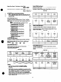 9
9
-
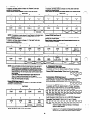 10
10
-
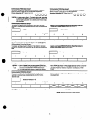 11
11
-
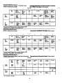 12
12
-
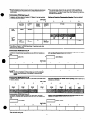 13
13
-
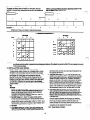 14
14
-
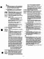 15
15
-
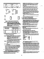 16
16
-
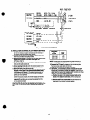 17
17
-
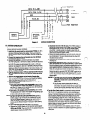 18
18
-
 19
19
-
 20
20
-
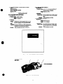 21
21
-
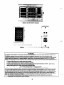 22
22


ADEMCO 4160-12 C-COM Installation Instructions Manual
- Category
- Fire protection
- Type
- Installation Instructions Manual
Ask a question and I''ll find the answer in the document
Finding information in a document is now easier with AI
Related papers
Other documents
-
 GE Interlogix NetworX NX-8 Installation guide
-
ADT 1010 User manual
-
 NAPCO 800S User manual
-
 Napco Security Technologies MAGNUM ALERT-825 User manual
-
 CADDX RANGER 7600 Installation guide
-
Honeywell Ademco VISTA-40 User manual
-
 Orbit Manufacturing RP-206 User manual
-
FBII XL-2T Installation And Setup Manual
-
-
 Napco Security Technologies WI1501A User manual


