Page is loading ...

POWER AVAILABILITY
PowerSure PSI™
USER MANUAL
1000 - 3000VA
120V


i
TABLE OF CONTENTS
IMPORTANT SAFETY INSTRUCTIONS . . . . . . . . . . . . . . . . . . . . . . . . . . . . . . . . . . . . . . . . . . . . . . . .1
1.0 GLOSSARY OF SYMBOLS . . . . . . . . . . . . . . . . . . . . . . . . . . . . . . . . . . . . . . . . . . . . . . . . . .3
2.0 I
NTRODUCTION . . . . . . . . . . . . . . . . . . . . . . . . . . . . . . . . . . . . . . . . . . . . . . . . . . . . . . . . . .4
3.0 M
AJOR COMPONENTS . . . . . . . . . . . . . . . . . . . . . . . . . . . . . . . . . . . . . . . . . . . . . . . . . . . .6
3.1 Transient Voltage Surge Suppression (TVSS) and EMI/RFI Filters. . . . . . . . . . . . . . . . . . . . 6
3.2 Relay . . . . . . . . . . . . . . . . . . . . . . . . . . . . . . . . . . . . . . . . . . . . . . . . . . . . . . . . . . . . . . . . . . . . . . 6
3.3 Automatic Voltage Regulator. . . . . . . . . . . . . . . . . . . . . . . . . . . . . . . . . . . . . . . . . . . . . . . . . . . 7
3.4 Battery Charger . . . . . . . . . . . . . . . . . . . . . . . . . . . . . . . . . . . . . . . . . . . . . . . . . . . . . . . . . . . . . 7
3.5 Battery . . . . . . . . . . . . . . . . . . . . . . . . . . . . . . . . . . . . . . . . . . . . . . . . . . . . . . . . . . . . . . . . . . . . 7
3.6 Inverter—1000/1440 Models Only. . . . . . . . . . . . . . . . . . . . . . . . . . . . . . . . . . . . . . . . . . . . . . . 7
3.7 DC-to-DC Converter—2200/3000 Models Only . . . . . . . . . . . . . . . . . . . . . . . . . . . . . . . . . . . . 7
3.8 Bi-Directional Converter—2200/3000 Models Only . . . . . . . . . . . . . . . . . . . . . . . . . . . . . . . . . 7
4.0 WHAT’S INCLUDED . . . . . . . . . . . . . . . . . . . . . . . . . . . . . . . . . . . . . . . . . . . . . . . . . . . . . . .8
5.0 INSTALLATION . . . . . . . . . . . . . . . . . . . . . . . . . . . . . . . . . . . . . . . . . . . . . . . . . . . . . . . . . .9
5.1 Preparation . . . . . . . . . . . . . . . . . . . . . . . . . . . . . . . . . . . . . . . . . . . . . . . . . . . . . . . . . . . . . . . . . 9
5.2 Tower UPS Installation . . . . . . . . . . . . . . . . . . . . . . . . . . . . . . . . . . . . . . . . . . . . . . . . . . . . . . . 9
5.3 Rack-Mount UPS Conversion and Installation . . . . . . . . . . . . . . . . . . . . . . . . . . . . . . . . . . . 10
5.4 External Battery Cabinet Installation . . . . . . . . . . . . . . . . . . . . . . . . . . . . . . . . . . . . . . . . . . 13
6.0 CONTROLS AND INDICATORS. . . . . . . . . . . . . . . . . . . . . . . . . . . . . . . . . . . . . . . . . . . . . . .14
6.1 ON/Alarm Silence/Battery Test Button . . . . . . . . . . . . . . . . . . . . . . . . . . . . . . . . . . . . . . . . . 14
6.2 OFF Button. . . . . . . . . . . . . . . . . . . . . . . . . . . . . . . . . . . . . . . . . . . . . . . . . . . . . . . . . . . . . . . . 14
6.3 Voltage Programming Button . . . . . . . . . . . . . . . . . . . . . . . . . . . . . . . . . . . . . . . . . . . . . . . . . 15
6.4 Load Level Indicators—4 green, 1 amber . . . . . . . . . . . . . . . . . . . . . . . . . . . . . . . . . . . . . . . . 15
6.5 Battery Level Indicators—5 green . . . . . . . . . . . . . . . . . . . . . . . . . . . . . . . . . . . . . . . . . . . . . 15
6.6 AC Input Indicator—Green . . . . . . . . . . . . . . . . . . . . . . . . . . . . . . . . . . . . . . . . . . . . . . . . . . . 15
6.7 Buck/Boost Indicator—Green . . . . . . . . . . . . . . . . . . . . . . . . . . . . . . . . . . . . . . . . . . . . . . . . . 15
6.8 Battery Indicator—Green/Amber . . . . . . . . . . . . . . . . . . . . . . . . . . . . . . . . . . . . . . . . . . . . . . 15
6.9 Over Temp Indicator—Amber . . . . . . . . . . . . . . . . . . . . . . . . . . . . . . . . . . . . . . . . . . . . . . . . . 16
6.10 Fault Indicator—Red . . . . . . . . . . . . . . . . . . . . . . . . . . . . . . . . . . . . . . . . . . . . . . . . . . . . . . . . 16
7.0 MODES OF OPERATION. . . . . . . . . . . . . . . . . . . . . . . . . . . . . . . . . . . . . . . . . . . . . . . . . . .17
7.1 Normal Mode . . . . . . . . . . . . . . . . . . . . . . . . . . . . . . . . . . . . . . . . . . . . . . . . . . . . . . . . . . . . . . 17

ii
7.2 Buck/Boost Mode . . . . . . . . . . . . . . . . . . . . . . . . . . . . . . . . . . . . . . . . . . . . . . . . . . . . . . . . . . . 17
7.3 Battery Mode . . . . . . . . . . . . . . . . . . . . . . . . . . . . . . . . . . . . . . . . . . . . . . . . . . . . . . . . . . . . . . 18
7.4 Battery Recharge Operation . . . . . . . . . . . . . . . . . . . . . . . . . . . . . . . . . . . . . . . . . . . . . . . . . . 18
8.0 COMMUNICATIONS . . . . . . . . . . . . . . . . . . . . . . . . . . . . . . . . . . . . . . . . . . . . . . . . . . . . . .19
8.1 DB-9 Connector . . . . . . . . . . . . . . . . . . . . . . . . . . . . . . . . . . . . . . . . . . . . . . . . . . . . . . . . . . . . 19
8.2 Remote Shutdown Via the DB-9 Connector . . . . . . . . . . . . . . . . . . . . . . . . . . . . . . . . . . . . . . 19
8.2.1 Any Mode Shutdown—Via Pins 5 & 6. . . . . . . . . . . . . . . . . . . . . . . . . . . . . . . . . . . . . . . . . . . . 19
8.2.2 Battery Mode Shutdown—Via Pins 4 & 5. . . . . . . . . . . . . . . . . . . . . . . . . . . . . . . . . . . . . . . . . 19
8.3 USB Interface Port . . . . . . . . . . . . . . . . . . . . . . . . . . . . . . . . . . . . . . . . . . . . . . . . . . . . . . . . . . 20
8.4 Data Line Protection Connectors. . . . . . . . . . . . . . . . . . . . . . . . . . . . . . . . . . . . . . . . . . . . . . . 20
8.5 UPS Intelligent Communications . . . . . . . . . . . . . . . . . . . . . . . . . . . . . . . . . . . . . . . . . . . . . . 20
9.0 VOLTAGE PROGRAMMING PROCEDURE . . . . . . . . . . . . . . . . . . . . . . . . . . . . . . . . . . . . . . .21
10.0 MAINTENANCE . . . . . . . . . . . . . . . . . . . . . . . . . . . . . . . . . . . . . . . . . . . . . . . . . . . . . . . . .22
10.1 Cleaning the UPS . . . . . . . . . . . . . . . . . . . . . . . . . . . . . . . . . . . . . . . . . . . . . . . . . . . . . . . . . . . 22
10.2 Maintaining Batteries . . . . . . . . . . . . . . . . . . . . . . . . . . . . . . . . . . . . . . . . . . . . . . . . . . . . . . . 22
10.3 Battery Replacement . . . . . . . . . . . . . . . . . . . . . . . . . . . . . . . . . . . . . . . . . . . . . . . . . . . . . . . . 22
10.3.1 Internal Battery Replacement Procedure . . . . . . . . . . . . . . . . . . . . . . . . . . . . . . . . . . . . . . . . . 23
11.0 TROUBLESHOOTING . . . . . . . . . . . . . . . . . . . . . . . . . . . . . . . . . . . . . . . . . . . . . . . . . . . . .24
12.0 SPECIFICATIONS . . . . . . . . . . . . . . . . . . . . . . . . . . . . . . . . . . . . . . . . . . . . . . . . . . . . . . . .26
12.1 Product Warranty Registration . . . . . . . . . . . . . . . . . . . . . . . . . . . . . . . . . . . . . . . . . . . . . . . . 29

iii
FIGURES
Figure 1 Front view of UPS . . . . . . . . . . . . . . . . . . . . . . . . . . . . . . . . . . . . . . . . . . . . . . . . . . . . . . . . . . . . . . . . 4
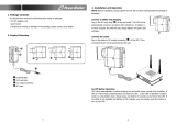
Figure 2 1000 and 1440VA PSI—rear view . . . . . . . . . . . . . . . . . . . . . . . . . . . . . . . . . . . . . . . . . . . . . . . . . . . 5
Figure 3 2200VA PSI—rear view . . . . . . . . . . . . . . . . . . . . . . . . . . . . . . . . . . . . . . . . . . . . . . . . . . . . . . . . . . . 5
Figure 4 3000VA PSI—rear view . . . . . . . . . . . . . . . . . . . . . . . . . . . . . . . . . . . . . . . . . . . . . . . . . . . . . . . . . . . 5
Figure 5 Line diagram of PowerSure PSI 1000VA & 1440VA . . . . . . . . . . . . . . . . . . . . . . . . . . . . . . . . . . . . 6
Figure 6 Line diagram of PowerSure PSI 2200VA & 3000VA . . . . . . . . . . . . . . . . . . . . . . . . . . . . . . . . . . . . 6
Figure 7 Support base for tower configuration. . . . . . . . . . . . . . . . . . . . . . . . . . . . . . . . . . . . . . . . . . . . . . . . . 9
Figure 8 Rack mount handles . . . . . . . . . . . . . . . . . . . . . . . . . . . . . . . . . . . . . . . . . . . . . . . . . . . . . . . . . . . . . 10
Figure 9 Fixed rails with inner members extended . . . . . . . . . . . . . . . . . . . . . . . . . . . . . . . . . . . . . . . . . . . . 10
Figure 10 Rack mounting rails and slide assemblies. . . . . . . . . . . . . . . . . . . . . . . . . . . . . . . . . . . . . . . . . . . . 11
Figure 11 REPO switch connections . . . . . . . . . . . . . . . . . . . . . . . . . . . . . . . . . . . . . . . . . . . . . . . . . . . . . . . . . 13
Figure 12 Load level indicators—4 green, 1 amber . . . . . . . . . . . . . . . . . . . . . . . . . . . . . . . . . . . . . . . . . . . . . 15
Figure 13 Battery level indicators—5 green. . . . . . . . . . . . . . . . . . . . . . . . . . . . . . . . . . . . . . . . . . . . . . . . . . . 15
Figure 14 Normal mode operation with 26-50% load. . . . . . . . . . . . . . . . . . . . . . . . . . . . . . . . . . . . . . . . . . . . 17
Figure 15 Buck/Boost mode operation with 51-75% load and 21-40% battery capacity . . . . . . . . . . . . . . . . 17
Figure 16 Battery mode at 61 – 80% battery capacity. . . . . . . . . . . . . . . . . . . . . . . . . . . . . . . . . . . . . . . . . . . 18
Figure 17 Low Battery mode . . . . . . . . . . . . . . . . . . . . . . . . . . . . . . . . . . . . . . . . . . . . . . . . . . . . . . . . . . . . . . . 18
Figure 18 Load Level Indicators . . . . . . . . . . . . . . . . . . . . . . . . . . . . . . . . . . . . . . . . . . . . . . . . . . . . . . . . . . . . 21
Figure 19 Battery replacement procedure . . . . . . . . . . . . . . . . . . . . . . . . . . . . . . . . . . . . . . . . . . . . . . . . . . . . 23
Figure 20 Status indicators . . . . . . . . . . . . . . . . . . . . . . . . . . . . . . . . . . . . . . . . . . . . . . . . . . . . . . . . . . . . . . . 24
TABLES
Table 1 DB-9 pin assignment . . . . . . . . . . . . . . . . . . . . . . . . . . . . . . . . . . . . . . . . . . . . . . . . . . . . . . . . . . . . 19
Table 2 Troubleshooting chart. . . . . . . . . . . . . . . . . . . . . . . . . . . . . . . . . . . . . . . . . . . . . . . . . . . . . . . . . . . . 25
Table 3 UPS specifications. . . . . . . . . . . . . . . . . . . . . . . . . . . . . . . . . . . . . . . . . . . . . . . . . . . . . . . . . . . . . . . 26
Table 4 Battery cabinet specifications . . . . . . . . . . . . . . . . . . . . . . . . . . . . . . . . . . . . . . . . . . . . . . . . . . . . . 27
Table 5 Battery run times . . . . . . . . . . . . . . . . . . . . . . . . . . . . . . . . . . . . . . . . . . . . . . . . . . . . . . . . . . . . . . . 28

iv

1
IMPORTANT SAFETY INSTRUCTIONS
SAVE THESE INSTRUCTIONS
This manual contains important safety instructions that should be followed during the installation
and maintenance of the UPS and batteries. Please read this manual thoroughly before attempting to
install or operate this UPS.
CONDITIONS OF USE: The input receptacle must be within 10 feet (3 meters) of the UPS.
Your UPS provides conditioned power to connected equipment. Maximum load must not exceed that
shown on UPS rating label. If uncertain, consult your local dealer, Liebert representative or the Lie-
bert Worldwide Support Group.
Placing magnetic storage media on top of the UPS may result in data corruption.
The equipment can be installed and operated by individuals without previous training.
!
WARNING
SAFETY PRECAUTIONS
To prevent the risk of fire or electric shock, install the UPS in a temperature and humidity
controlled room, free of conductive contaminants, moisture, flammable liquids, gases and
corrosive substances.
Operate the UPS only from a properly grounded (earthed) 110-127 VAC, 50Hz or 60Hz AC
supply.
To reduce the risk of electric shock, do not remove the cover, as it has no user-serviceable
parts inside except the internal battery pack. Some components are live, even when AC power
is disconnected. For service, contact a qualified technician.
!
CAUTION
Although your UPS has been designed and manufactured to ensure personal safety, improper
use can result in electrical shock or fire. To ensure safety, please observe the following rules:
• Turn Off and unplug your UPS before cleaning. Do not use liquid or aerosol cleaners. A dry
cloth is recommended to remove dust from the surface of your UPS.
• Do not install or operate your UPS in or near water.
• Do not place UPS on an unstable cart, stand or table.
• Do not place UPS under direct sunlight or close to heat emitting sources.
• Never block or insert any objects into the ventilation holes or other openings of the UPS.
Keep all vents free of dust accumulation that could restrict air flow.
• Do not place UPS power cord in any area where it may get damaged by heavy objects.
!
WARNING
If your UPS demonstrates any of the following conditions, turn Off and unplug your UPS from
the outlet and contact your local dealer, Liebert representative or Liebert Worldwide Support
Group:
• The power cord or plug is damaged.
• Liquid has been spilled on the UPS.
• The circuit protector trips frequently.
• The UPS does not operate in accordance with the user manual.
!
CAUTION
DO NOT CONNECT equipment that could overload the UPS or demand half-wave
rectification from the UPS, for example: electric drills, vacuum cleaners, laserjet/inkjet
printers, hair dryers, overhead projectors.

2
!
CAUTION
BATTERY HANDLING PRECAUTIONS
Servicing of batteries should be performed or supervised by personnel knowledgeable of
batteries and required precautions. Keep unauthorized personnel away from the batteries.
A battery can present a risk of electrical shock and high short-circuit current. The following
precautions should be observed when working on batteries:
• Remove watches, rings, and other metal objects.
• Use tools with insulated handles.
• Do not dispose battery or batteries in a fire. The battery may explode.
• Do not open or mutilate the battery or batteries. Released electrolyte is harmful to skin and
eyes. It may be toxic.
• When replacing the battery, use same number and type of battery as the suitable recom-
mended type of battery listed in specification table in back of this manual.
• Handle, transport and recycle batteries in accordance with local regulations.
NOTE
This device complies with part 15 of the FCC Rules. Operation is subject to the following two
conditions: (1) This device may not cause harmful interference, and (2) this device must accept
any interference received, including interference that may cause undesired operation.
This equipment uses, generates and can radiate radio frequency energy and, if not installed
and used in accordance with the instructions, may cause harmful interference with radio
communications. However, there is no guarantee that interference will not occur in a particular
installation. If this equipment does cause harmful interference to radio or television reception,
which can be determined by turning the equipment Off and On, the user is encouraged to try to
correct the interference by one or more of the following measures:
• Reorient or relocate the receiving antenna.
• Increase the separation between the UPS and the receiver.
• Connect the UPS into an outlet on a circuit different from the one on which the receiver is
connected.

Glossary of Symbols
3
1.0 GLOSSARY OF SYMBOLS
.
Risk of electrical shock
Indicates caution followed by important instructions
Requests the user to consult the manual
Indicates the unit contains a valve-regulated lead acid battery
Recycle
DC voltage
Equipment grounding conductor
Bonded to ground
AC voltage
ON/Alarm Silence/Battery Test
OFF
Voltage Programming Button
i

Introduction
4
2.0 INTRODUCTION
Congratulations on your choice of the Liebert PowerSure™ PSI Uninterruptible Power Supply (UPS).
It provides conditioned power to microcomputers and other sensitive electronic equipment.
Upon generation, AC power is clean and stable. However, during transmission it may be subject to
voltage sags, spikes, or complete power failure which may interrupt computer operations, cause data
loss, or even damage equipment. The PowerSure PSI protects equipment from these disturbances.
The PowerSure PSI comes in nominal power ratings of 1000, 1440, 2200, or 3000 VA. Refer to the
Specifications section for details.
The PowerSure PSI is a 2U, line-interactive UPS that may be installed in a rack or used in a tower
configuration. A line-interactive UPS continuously conditions and regulates its output voltage,
whether utility power is present or not. It supplies connected equipment with clean, sinewave power
to simulate the power generated by the utility. Sensitive electronic equipment operates best from
sinewave power.
For ease of use, the PowerSure PSI contains Status Indicators to display Load Level, Battery Level,
Buck/Boost, Over Temperature and Battery. It also provides self-diagnostic tests, a combination ON/
Alarm Silence/Battery Test button, an OFF button and Voltage Programming button.
The PowerSure PSI has USB, DB-9 (RS232/contact closure) and Intellislot interface ports for commu-
nications between the UPS and a LAN server or other computer systems. The DB-9 port provides
detailed operating information including voltages, currents, and alarm status to the host system
when used in conjunction with Liebert’s MultiLink software. MultiLink software can also remotely
control UPS operation. The USB port provides detailed operating information and alarm status to the
host system when used in conjunction with the Liebert Human Interface Device (HID) and Microsoft
Power Manager software.
Figure 1 Front view of UPS
Voltage
Programming
Button
ON/Alarm Silence/
Battery Test Button
OFF Button
Battery Level
Indicators
Load Level
Indicators
UPS Display
(bezel removed)
UPS Status
Indicators
Fault
Indicator

Introduction
5
Figure 2 1000 and 1440VA PSI—rear view
Figure 3 2200VA PSI—rear view
Figure 4 3000VA PSI—rear view
INPUT
INPUT
BREAKER
PUSH TO RESET
PHONE / FAX / MODEM / NETWORK
PROTECTION
BATTERY
CONNECTOR
1440VA/DC 48V/30A
1000VA/DC 48V/20A
1
2
3
4
INTELLISLOT
LOAD 2 LOAD 1
IN
OUT
+
-
REPO
RS-232
Data Line
Connectors
Circuit Breaker
USB Port
RS232 (DB-9)
Port
Intellislot Port
Attached Power
Cord, 10ft (3m)
REPO
Output
Receptacles
External Battery
Cabinet Connector
INPUT
INPUT
BREAKER
PUSH TO RESET
PHONE / FAX /
MODEM / NETWORK
PROTECTION
BATTERY
CONNECTOR
DC 72V / 30A
1
2
3
4
INTELLISLOT
15A/120VAC
+
-
LOAD 2
BREAKER
LOAD 1
BREAKER
IN
OUT
REPO
RS-232
Data Line
Connectors
Circuit Breaker
USB
Port
RS232 (DB-9)
Port
Intellislot
Port
Attached Power
Cord, 10ft (3m)
REPO
Output
Receptacles
External Battery
Cabinet Connector
Circuit Breaker
Circuit Breaker
INPUT
INPUT
BREAKER
PUSH TO RESET
PHONE / FAX /
MODEM / NETWORK
PROTECTION
BATTERY
CONNECTOR
DC 72V / 40A
+
1
2
3
4
-
INTELLISLOT
LOAD 3
LOAD 1
BREAKER
LOAD 2
BREAKER
15A / 120 VAC
IN
OUT
REPO
RS-232
Data Line
Connectors
Circuit Breaker
USB
Port
RS232 (DB-9)
Port
Intellislot
Port
Attached Power
Cord, 10ft (3m)
REPO
Output
Receptacles
External Battery
Cabinet Connector
Circuit Breaker
Circuit Breaker

Major Components
6
3.0 MAJOR COMPONENTS
Figure 5 Line diagram of PowerSure PSI 1000VA & 1440VA
Figure 6 Line diagram of PowerSure PSI 2200VA & 3000VA
3.1 Transient Voltage Surge Suppression (TVSS) and EMI/RFI Filters
These UPS components provide surge protection and filter both electromagnetic interference (EMI)
and radio frequency interference (RFI). They minimize surges or interference present in the utility
line and keep the sensitive equipment protected.
3.2 Relay
In Normal mode the Relay passes utility AC power to the connected load. When input utility voltage
or frequency is outside acceptable limits, the Relay activates and transfers the UPS to battery.
Input
EMI/RFI
Filter
Relay
AVR
Transformer
Output
InverterBatteryCharger
G G
Input
EMI/RFI
Filter
Relay
AVR
Transformer
Output
Bi-Directional
Converter
BatteryCharger
DC-to-DC
Converter
G G

Major Components
7
3.3 Automatic Voltage Regulator
The Automatic Voltage Regulator (AVR) protects connected equipment from power spikes, sags and
other abnormalities by raising (boosting) or lowering (bucking) the output voltage as needed. This
keeps the UPS output voltage within the connected equipment’s tolerance and accommodates wide
utility voltage fluctuations without utilizing the batteries.
3.4 Battery Charger
In Normal mode, the Battery Charger converts utility AC power into regulated DC power to float
charge the battery. It is continuously charging the battery whenever the UPS is plugged into a power
outlet and utility power is within acceptable limits - even if the UPS is turned Off.
3.5 Battery
The PowerSure PSI utilizes valve-regulated, nonspillable, lead acid batteries. To maintain battery
design life, operate the UPS in an ambient temperature of 68°F to 77°F (20°C to 25°C). Optional
external battery cabinets are available to extend battery run times.
3.6 Inverter—1000/1440 Models Only
In battery mode operation, the inverter utilizes the DC output of the battery and inverts it into pre-
cise, regulated, sinewave AC power.
3.7 DC-to-DC Converter—2200/3000 Models Only
The DC-to-DC Converter utilizes energy from the battery system and raises the DC voltage to the
optimum operating voltage for the Bi-Directional Converter. This allows the Bi-Directional Converter
to operate continuously at its optimum efficiency and voltage, thus increasing reliability.
3.8 Bi-Directional Converter—2200/3000 Models Only
In normal operation, the Bi-Directional Converter changes utility AC power into regulated DC power
to “float charge” the battery system. This converter is continuously charging the battery whenever the
UPS is plugged into a power outlet and utility power is within acceptable limits—even if the UPS is
turned Off. When utility power fails, the Bi-Directional Converter draws energy from the battery
through the DC-to-DC Converter and inverts it into a regulated sinewave supplying power to con-
nected equipment.

What’s Included
8
4.0 WHAT’S INCLUDED
The PowerSure PSI is shipped with the following items:
• PowerSure PSI user manual
• Warranty card
• MultiLink software CD
• MultiLink serial cable, 10 ft (3m)
• USB cable, 6 ft (1.8m)
• RJ-11 cord, 7 ft (2.1m)
• Rack mount handles
• Support base
• Fixed rails
• Mounting hardware (screws/washers)
•Front bezel
• Vertical display overlay
MultiLink
software CD
RJ-11 cord
7 ft (2.1m)
USB cable
6 ft (1.8m)
Fixed rails
Mounting hardware
(screws & washers)
Front bezel
Support base
Vertical
display
overlay
Rack mount
handles
MultiLink
serial cable
10 ft (3m)

Installation
9
5.0 INSTALLATION
5.1 Preparation
1. Visually inspect the UPS for freight damage. Report damage to the carrier and your local dealer
or Liebert representative.
2. Decide where to place the PowerSure PSI. Install the UPS indoors in a controlled environment
where it cannot be accidentally turned Off. Place it in an area of unrestricted airflow around the
unit, away from water, flammable liquids, gases, corrosives, and conductive contaminants.
Maintain a minimum clearance of 4 inches (100mm) in the front and rear of the UPS. Maintain an
ambient temperature range of 32°F to 104°F (0°C to 40°C).
3. The PowerSure PSI may be installed in either a tower configuration or in a rack, depending on
available space and use considerations. Determine the type of installation and follow the
appropriate instructions in either Tower UPS Installation or Rack-Mount UPS Conversion
and Installation.
5.2 Tower UPS Installation
When using the PowerSure PSI in a tower configuration, use the included support base (shown below,
left) to stabilize the UPS. If two or more battery cabinets are added, the spacers—included with the
battery cabinets—should be used to accommodate the additional cabinets.
Figure 7 Support base for tower configuration
1. To orient the display for vertical viewing, remove the front plastic bezel by pulling forward evenly
on both sides.
2. Peel the backing from the vertical display overlay and apply to the existing display.
3. Snap the front bezel back into place.
!
CAUTION
The UPS is heavy (see Table 4 - Battery cabinet specifications). Take proper precautions
when lifting or moving it.
NOTE
UPS operation in temperatures above 77°F (25°C) reduces battery life.
Tower Stand - Fully Extended
Spacers Can be Added to Accommodate External Battery Cabinets
Connectors Snap into Slots on Base

Installation
10
5.3 Rack-Mount UPS Conversion and Installation
1. For fixed rail installations, install the rack mount handles using four (4) M4x6 screws (see
Figure 8).
Figure 8 Rack mount handles
2. Unpack the two fixed rail assemblies and mounting hardware. Loosen the wing nuts and extend
the inner members to their outermost position (see Figure 9).
Figure 9 Fixed rails with inner members extended
3. Determine the height position inside the rack enclosure where you want to mount the UPS or
battery cabinet. Make sure fixed rails are at the same mounting height on each of the four (4) rack
mounting rails.
NOTE
When rack mounted, the UPS must be supported by a shelf, slide rails, brackets or fixed rails
on each side. The rack mount handles WILL NOT support the weight of the UPS. They are
used to move the UPS into and out of the rack.
!
CAUTION
Reduce the risk of tipping the rack enclosure by placing the UPS or battery cabinet in the
lowest possible rack position.
Rack Mount Handles
Two (2) M4x6
Flat Head Screws
Two (2) M4x6
Flat Head Screws
M4x6 Flat Screw
Wing Nuts for
Adjustment
Adjustable Length
Maximum 800 mm
Minimum 485 mm
Adjustable Slide
Assembly

Installation
11
4. Attach the two (2) fixed rails to the racks mounting rails. The fixed rail assemblies fit on the
inside of the rack mounting rails.
5. Insert two (2) M5 flat head screws loosely (finger-tight) into the top and bottom holes on the front
of the fixed rail assembly (see Figure 10).
6. Extend fixed rail by sliding inner member backward until it touches the rear rack mounting rail.
7. Insert two (2) M5 screws loosely (finger-tight) into top and bottom holes on the rear of the fixed
rail assembly.
8. Check alignment of fixed rails and tighten all screws to ensure locking action.
Figure 10 Rack mounting rails and slide assemblies
9. Lay the UPS in rack-mounting position on the fixed rails. The UPS should move smoothly forward
and backward on the fixed rails. If not, recheck alignment.
10. Use the extra M5 screws provided, secure front of the UPS to rack mounting rails to prevent the
UPS from sliding out of position.
11. Plug the PowerSure PSI’s attached 10 ft. (3m)
power cord into a dedicated wall receptacle
properly protected by a circuit breaker or fuse in
accordance with national and local electrical codes.
Use a 15A-rated device for the 1000 or 1440 VA
units, 30 amp for the 2200 VA or 3000 VA units.
The wall receptacle must be grounded.
12. Turn On the UPS by pressing the ON button.
Check that the AC Input Indicator is not flashing.
If it is flashing, refer to 11.0 - Troubleshooting.
Then turn On the connected equipment. The UPS
is now providing conditioned power to your
equipment.
!
CAUTION
Lifting equipment into rack may be a two-person job, depending on weight of equipment.
!
CAUTION
To maintain safety (SELV) barriers and electromagnetic compatibility, signal cables should
be segregated and run separately from power cables.
A - Washer
B - M5x12 Flat Screw
B
A
B
B
B
A
A
A
Vertical
overlay
for tower
UPS
Horizontal
overlay for
rack UPS

Installation
12
13. Connect Phone/Fax/DSL/Network/Modem devices to data line connectors.
14. Communication options (see 8.0 - Communications for details):
Option 1 - Serial Communications
Serial communications provides parametric data, for example, input voltage and battery voltage.
a. Connect MultiLink serial cable included with the UPS to communications port.
b. Install the MultiLink software. The software and installation instructions, as well as the user
manual, are on the CD included in the PowerSure PSI package.
Option 2 - Contact Closure Communications
Contact Closure communications provides on-battery and low-battery signals for orderly shut-
down.
a. Refer to the MultiLink user manual for instructions on making your own contact closure
cable.
b. Install the MultiLink software. The software and installation instructions, as well as the user
manual, are on the CD included in the PowerSure PSI package.
Option 3 - USB Communications
a. Connect USB cable provided with the UPS to the PSI’s USB port and the USB port on your
computer. The PSI will work automatically with your built-in power management software on
Windows XP and 2000 and Mac OS 10.2 or later (see 8.3 - USB Interface Port for details).
Option 4 – Intellislot
The UPS contains one communication slot, called “Intellislot™,” to allow the operator to field
install optional communication cards. These optional cards allow the UPS to communicate via
either OpenComms Web Card (OCWEBCARD), connected directly to the LAN; or Intellislot Relay
Interface card (RELAYCARD-INT) communication card. Once the OCWEBCARD is installed, the
Serial communication via the RS232 is disabled. The USB, Intellislot, and Contact Closure com-
munications operate in parallel.
15. REPO Switch—The PowerSure PSI is equipped with a Remote Emergency Power Off (REPO)
switch.
The user must supply a means of interfacing with the REPO circuit to allow disconnecting the
UPS input feeder breaker to remove all sources of power to the UPS and connected equipment to
comply with national and local wiring codes and regulations.
INPUT
INPUT
BREAKER
PUSH TO RESET
PHONE / FAX / MODEM / NETWORK
PROTECTION
BATTERY
CONNECTOR
1440VA/DC 48V/30A
1000VA/DC 48V/20A
INTELLISLOT
LOAD 2 LOAD 1
IN
OUT
+
-
REPO
RS-232
1
2
3
4
RJ11/RJ45
connection

Installation
13
Figure 11 REPO switch connections
5.4 External Battery Cabinet Installation
Optional Liebert external battery cabinets may be connected to the UPS to provide additional battery
run time. External battery cabinets are designed to be placed all on one side of the UPS or stacked
beneath the UPS. The run time is limited to a maximum of four (4) hours.
1. Visually inspect the external battery cabinet for freight damage. Report damage to the carrier
and your local dealer or Liebert representative.
2. The rack-mount handles are shipped with the external battery cabinet and may be installed at
this time (see 5.3 - Rack-Mount UPS Conversion and Installation).
3. Fixed rails and securing hardware ship with the external battery cabinet. Fasten the fixed rails
into position with the screws per the instructions included with the UPS. Repeat
Steps 1 through 10 from 5.3 - Rack-Mount UPS Conversion and Installation.
4. Use the support bases included with the UPS for the tower option to prevent tip-over. One
additional set of support base spacers ships with each external battery cabinet.
5. Connect the supplied external
battery cabinet cable to the rear of
the external battery cabinet, then to
the rear of the UPS, as shown at
right.
6. The UPS is now equipped with
additional backup battery run time.
For approximate battery run times,
refer to Table 5 - Battery run
times.
!
CAUTION
The external battery cabinet(s) are heavy (see 12.0 - Specifications). External battery
cabinets can be used in rack-mount or tower configuration. Take proper precautions when
lifting them.
REPO connections
for normally open
switch system
REPO Switch
as shipped
REPO connections
for normally closed
switch system (fail-safe)
1234
Key to REPO switch connections
1. 24 VDC,
2. Sense
3. Sense
4. Ground
REPO Connection
12341234
LOAD 2
INPUT
INPUT
BREAKER
PUSH TO RESET
PHONE / FAX / MODEM / NETWORK
PROTECTION
BATTERY
CONNECTOR
1440VA/DC 48V/30A
1000VA/DC 48V/20A
BATTERY
CONNECTOR
1440VA/DC 48V/30A
1000VA/DC 48V/20A
BATTERY
CONNECTOR
1440VA/DC 48V/30A
1000VA/DC 48V/20A
1
2
3
4
INTELLISLOT
LOAD 1
IN
OUT
+
-
REPO
RS-232

Controls and Indicators
14
6.0 CONTROLS AND INDICATORS
6.1 ON/Alarm Silence/Battery Test Button
This button controls output power to connected load(s) and has three functions:
•On
• Alarm Silence
•Battery Test
ON—When the UPS is Off, pressing the ON/Alarm Silence/Battery Test button for more than one
(1) second will start the UPS, and an audible alarm sounds briefly. The UPS is capable of starting on
battery (battery start).
Alarm Silence—When a UPS audible alarm is active, pressing and releasing the ON/Alarm Silence/
Battery Test button will silence the active audible alarm, whether utility power is present or not.
Once the alarm silence function has been activated, all active audible alarms will remain silenced
until a new alarm condition is detected.
Battery Test—To initiate a manual battery test, press the ON/Alarm Silence/Battery Test button for
at least one second while operating from utility power with no alarm conditions present.
• If all five (5) Battery indicators are not illuminated, allow the UPS to recharge the batteries for
24 hours.
• After 24 hours, retest the batteries.
• After the batteries have been retested, if all five (5) Battery indicators are not illuminated, con-
tact your local dealer, Liebert representative or Liebert Worldwide Support Group.
6.2 OFF Button
When the UPS is on (in either Normal or Battery mode), pressing the OFF button for more
than one (1) second will shut down the UPS. An audible alarm sounds briefly.
NOTE
The LOW BATTERY, OVER TEMP and OVERLOAD warning
audible alarms CANNOT be silenced.
All indicators illuminated
for illustrative purposes only.
/