Omega CN243 Series Owner's manual

Type
Owner's manual
CN243 SERIES
Controllers
For latest product manuals:
www.omegamanual.info
Shop online at
omega.com
sm
User’s Guide
®
Servicing North America:
U.S.A.: Omega Engineering, Inc., One Omega Drive, P.O. Box 4047
Stamford, CT 06907-0047 USA
Toll-Free: 1-800-826-6342 (USA & Canada only)
Customer Service: 1-800-622-2378 (USA & Canada only)
Engineering Service: 1-800-872-9436 (USA & Canada only)
Tel: (203) 359-1660 Fax: (203) 359-7700
For Other Locations Visit
omega.com/worldwide
The information contained in this document is believed to be correct, but OMEGA accepts no
liability for any errors it contains, and reserves the right to alter specifications without notice.
ATR243 - User manual - 3
Table of contents
1 Safety guide lines ......................................................................................................................................5
2 Model identification .................................................................................................................................5
3 Technical Data ...........................................................................................................................................5
3.1 General data .....................................................................................................................................5
3.2 Hardware data .................................................................................................................................6
3.3 Software data ................................................................................................................................... 6
4 Dimensions and Installation .................................................................................................................. 7
4.1 Panel Assembly ................................................................................................................................8
4.2 Electronics Removal ........................................................................................................................ 8
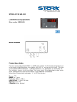
5 Electrical wirings .......................................................................................................................................9
5.1 Wiring diagram ................................................................................................................................9
6 Display and Key Functions .................................................................................................................... 15
6.1 Numeric Indicators (Display) ...................................................................................................... 15
6.2 Meaning of Status Lights (Led)...................................................................................................15
6.3 Keys ....................................................................................................................................................16
7 Controller Functions ............................................................................................................................... 16
7.1 Modifying Main Setpoint and Alarm Setpoint Values ......................................................... 16
7.2 Auto-Tuning ....................................................................................................................................16
7.3 Manual Tuning ...............................................................................................................................16
7.4 Automatic Tuning .......................................................................................................................... 17
7.5 Soft-Sta rt .......................................................................................................................................... 17
7.6 Automatic / Manual Regulation for % Output Control ....................................................... 17
7.7 Pre-Programmed Cycle ................................................................................................................18
7.8 CN-Config-Module (optional) ....................................................................................................19
7.9 Latch-on function......................................................................................................................... 20
7.10 Loop Break Alarm On Current Trasformer ............................................................................. 20
7.11 Digital Input Functions ............................................................................................................... 22
7.12 Dual Action Heating-Cooling ................................................................................................... 23
8 Serial Communication ...........................................................................................................................24
9 Enter configuration ................................................................................................................................ 29
9.1 Loading default values................................................................................................................ 29
10 Table of Configuration Parameters ................................................................................................... 30
11 Alarm Intervention Modes ....................................................................................................................42
12 Table of Anomaly Signals ......................................................................................................................45
13 Configuration EASY-UP ........................................................................................................................ 46
ATR243 - User manual - 5
Introduction
Thank you for choosing a Omega controller.
With CN243 model Omega integrates in a single device all options for sensor reading and
actuators command, beside extended supply range 24…230 Vac/Vdc. With 18 selectable
sensors and outputs configurable as relay, SSR command, 4…20 mA and 0…10 Volt the
user or retailer can reduce stock needs.
The series includes also a model with serial communication RS485 Modbus RTU and with
a loading control function via current transformer. The possibility to repeat parametri-
zation is simplified by the CN-Config-Module with internal battery that do not require
power supply for the controller.
1 Safety guide lines
Read carefully the safety guidelines and programming instructions contained in this
manual before using/connecting the device.
Disconnect power supply before proceeding to hardware settings or electrical wirings.
Only qualified personnel should be allowed to use the device and/or service it and in
accordance to technical data and environmental conditions listed in this manual.
Do not dispose electric tools together with household waste material. In observance
European Directive 2002/96/EC on waste electrical and electronic equipment and its
implementation in accordance with national law, electric tools that have reached the end
of their life must be collected separately and returned to an environmentally compatible
recycling facility.
2 Model identification
CN243 series includes three versions. Looking at the table here below it is possible to find
the required model.
Power supply 24…230 Vac/Vdc +/-15% 50/60 Hz – 5,5 VA
CN243-R1F2 2 relays 5 A or 1 relay + 1 Ssr/V/mA
CN243-R1R2F3 2 relays 5 A + 1 Ssr/V/mA + RS485 + current transformer*
CN243-
R1R2R3F4C4
3 relays 5 A + 1 Ssr/V/mA + current transformer*
* Models with current transformer input for “Loop Break Alarm” function.
3 Technical Data
3.1 General data
Indicators
4x0.40 inch displays
4x0.30 inch displays
Operating
temperature
Temperature 0-45 °C
Humidity 35..95 uR%
Sealing
IP65 front panel (with gasket)
IP20 box and terminals
Material PC ABS UL94VO self-extinguishing
Weight 165 g (-20ABC) / 185 g (-21/31ABC)
6 - ATR243 - User manual
3.2 Hardware data
Power supply
Extended range 24..230 Vac/Vdc
±15% 50/60 Hz
Consumption: 5.5 VA.
Analogue
imput
1: AN1 configurable via software.
Input: Thermocouple type K, S, R,
J. Automatic compensation of cold
junction from 0°C to 50°C.
Thermoresistance:
PT100, PT500, PT1000, Ni100,
PTC1K, NTC10K (β 3435K, OMEGA),
NTC2252-OMEGA. Linear: 0-10 V,
0-20 or 4-20 mA, 0-40 mV.
Current transformer: 50 mA, 1024
points on version CN243-R1R2F3/
R1R2R3F4C4. Potentiometers: 6
KΩ, 150 KΩ.
Tolerance (25 °C) +/-0.2% ±1 digit
for thermocouple input, thermo
resistance and V / mA.
Cold junction accuracy 0.1 °C/°C.
Impedance:
0-10 V: Ri>110 KΩ
0-20 mA: Ri<5 Ω
4-20 mA: Ri<5 Ω
0-40 mV: Ri>1 MΩ
Relay
output
2 Relays (CN243-R1F2/ R1R2F3).
3 Relays (CN243-R1R2R3F4C4).
Configurable as command and / or
alarm output.
Contacts
5 A - 250 V~.
Resistive load.
SSR/V/mA
output
1 SSR Linear 0/4…20mA or
0..10 Volt.
Deselecting OUT2 relay on
CN243-R1F2. Configurable as
command output or retransmis-
sion of setpoint or process.
12V / 30mA (min. 10.5 V DC).
Configurable:
0-10 V with 9500 points +/-0.2%
(F.s.)
0-20 mA with 7500 points +/-0.2%
(F.s.)
4-20 mA with 6000 points +/-0.2%
(F.s.)
3.3 Software data
Regulation
algorithms
ON - OFF with hysteresis.
P, P.I., P.I.D., P.D. with proportional time.
Proportional
band
0...9999 °C or °F
Integral time 0,0...999,9 sec. (0 excludes integral function)
Derivative time 0,0...999,9 sec. (0 excludes derivative function)
Controller
functions
Manual or automatic Tuning, configurable alarms, protection of
command and alarm setpoints, activation of functions via digital
input, preset cycle with Start / Stop.
ATR243 - User manual - 7
4 Dimensions and Installation
15
1116
234
12131415
1 6
12
3
4
5
11 13 14 15 1612
6 7 8 9 10
CN1
1 6
DIMA DI
FORATURA
FRONTAL PANEL
CUT-OUT
46 X 46 mm
48 mm
48 mm 106.5 mm10.5 18
Suggested thickness / Spessore suggerito 2 ÷ 6 mm
CN-CONFIG-MODULE
(optional)
CN-CONFIG-MODULE
CN243
8 - ATR243 - User manual
4.1 Panel Assembly
1
1
2
2
Method of panel assembly and fi xing of
anchorage hooks.
1
2
To dismantle, use a screwdriver and
slightly force the fi xing hooks to remove
them from the fi xing guide.
4.2 Electronics Removal
To remove the electronics, grip the front part using the two specifi c side ridges.
1
1
2
Disconnect the device from the mains before starting to confi gurate or service it.
ATR243 - User manual - 9
5 Electrical wirings
Although this controller has been designed to resist noises in an industrial
environment, please notice the following safety guidelines:
Separate control lines from the power wires.
Avoid the proximity of remote control switches, electromagnetic meters, powerful
engines.
Avoid the proximity of power groups, especially those with phase control.
5.1 Wiring diagram
CN243-R1F2
CN243-R1R2F3 CN243-R1R2R3F4C4
V/I
5.1.a Power
10
24...230V
AC/DC
SUPPLY
9
Switching power supply with extended range 24…230 Vac/
dc ±15% 50/60 Hz – 5,5 VA (with galvanic isolation).
10 - ATR243 - User manual
5.1.b AN1 Analogue Input
For thermocouples K, S, R, J.
Comply with polarity.
For possible extensions, use a compensated wire
and terminals suitable for the thermocouples used
(compensated).
When shielded cable is used, it should be grounded at
one side only.
Rosso
Red
Bianco
White
Rosso
Red
For thermoresistances PT100, NI100.
For the three-wire connection use wires with the same
section.
For the two-wire connection short-circuit terminals 1
and 3.
When shielded cable is used, it should be grounded at
one side only.
Select internal jumper JP3 as in the fi gure.
For thermoresistances NTC, PTC, PT500, PT1000 e poten-
tiometers.
When shielded cable is used, it should be grounded at one
side only to avoid ground loop currents.
For linear signals V / mA.
Comply with polarity.
When shielded cable is used, it should be grounded at
one side only.
Select internal jumper JP3 as in the fi gure.
If jumpers are not properly selected, 12 Vdc /
30 mA are not available on terminal 3 to
power the sensor.
ATR243 - User manual - 11
5.1.c Example of Connection for linear input Volt and mA
+12 V
30 mA
For signals 0….10 V.
Comply with polarity.
+12 V
30 mA
For signals 0/4….20 mA with three-wire sensor.
Comply with polarity:
A= Sensor output
B= Sensor ground
C= Sensor power (+12Vdc / 30mA)
For signals 0/4….20 mA with external power of sensor.
Comply with polarity:
A= Sensor output
B= Sensor ground
+12 V
30 mA
For signals 0/4….20 mA with two-wire sensor.
Comply with polarity:
A= Sensor output
C= Sensor power supply (+12Vdc / 30mA)
5.1.d Serial Input (only CN243-R1R2F3)
RS485 Modbus RTU communication.
5.1.e Relay Q1 Output
Capacity 5 A / 250 V~ for resistive loads.
NB: see graphic next page.
12 - ATR243 - User manual
5.1.f Relay Q2 output for CN243-R1F2
Capacity 5 A / 250 V~ for resistive loads.
To select Q2 as relay output, verify that jumpers JP5 and
JP7 are not inserted.
NB: see graphic next page.
Connecting a load without removing the
jumpers will permanently damage the
controller.
5.1.g Relay Q2 output for CN243-R1R2F3 and CN243-R1R2R3F4C4
Capacity 5 A / 250 V~ for resistive loads.
NB: see graphic.
5.1.h Relay Q3 output for CN243-R1R2R3F4C4
Q3 Relay Output on CN243-R1R2R3F4C4.
NB: see graphic.
Electrical endurance Q1 / Q2 / Q3:
5 A, 250 Vac, resistive loads, 10
5
operations.
20/2 A, 250 Vac, cosφ = 0.3, 10
5
operations.
ATR243 - User manual - 13
5.1.i SSR output
SSR/V/mA
5
+
4
-
SSR command output 12 V / 30 mA (min. 10.5 V DC).
Insert JP5 and JP7 and select JP9 as in the
gure to use the SSR output.
5.1.j mA / Volt output
SSR/V/mA
5
+
4
-
Linear output in mA confi gurable using parameters
as command (parameter
c.out
) or retransmission of
process-setpoint (parameter
rEt r.
).
Insert JP5 and JP7 and select JP9 as in
gure to use the output in mA (Jumpers
supplied inside packaging).
SSR/V/mA
5
+
4
-
Linear output in Volt confi gurable using parameters
as command (parameter
c.out
) or retransmission of
process-setpoint (parameter
rEt r.
).
Insert JP5 and JP7 and select JP9 as in
gure to use the linear output in Volt
(Jumpers supplied inside packaging).
14 - ATR243 - User manual
5.1.k Current Transformer Input on CN243-R1R2F3 and CN243-R1R2R3F4C4
Input 50 mA for current transformer.
Sampling time 80 ms.
Confi gurable by parameters.
Insert JP4 and JP6 as in fi gure to select the
amperometric transformer input.
5.1.l Digital Input on CN243-R1F2
+ 12V
GND
I D
3
2
Digital input using parameter
d G ti
.
The use of digital input in this version is possible only
with TC sensors, 0…10 V, 0/4…20 mA and 0…40 mV.
Select internal jumper JP3 as in fi gure.
5.1.m Digital Input on CN243-R1R2F3 and CN243-R1R2R3F4C4
+ 12V
GND
I D
16
15
Digital input using parameter
d G ti
.
Insert JP4 as in fi gure to select the digital
input.
ATR243 - User manual - 15
6 Display and Key Functions
A1
C2
C1
A2
1
3
4
8 9
10
5
6
7
2
CN243
6.1 Numeric Indicators (Display)
1
1234
Normally displays the process. During the configuration phase, it
displays the parameter being inserted.
2
1234
Normally displays the setpoint. During the configuration phase, it
displays the parameter value being inserted.
6.2 Meaning of Status Lights (Led)
3 C1 C2
ON when the output command is on.
C1 with relay/SSR/mA/Volt command or C1 (open) and C2
(close) for a motorised valve command.
4 A1 A2 A3 ON when the corresponding alarm is on.
5 MAN
ON when the “Manual” function is on.
6 TUN
ON when the controller is running an Autotune” cycle.
7 REM ON when the controller communicates via serial port.
16 - ATR243 - User manual
6.3 Keys
8
Allows to increase the main setpoint.
During the configuration phase, allows to slide through
parameters. Together with the
SET
key it modifies them.
Pressed after the
SET
key it allows to increase the alarm setpoint.
9
Allows to decrease the main setpoint.
During the configuration phase, allows to slide through
parameters. Together with the
SET
key it modifies them.
Pressed after the
SET
key it allows to decrease the alarm setpoint.
10
SET
Allows to display the alarm setpoint and runs the autotuning
function.
Allows to vary the configuration parameters.
7 Controller Functions
7.1 Modifying Main Setpoint and Alarm Setpoint Values
The setpoint value can be changed by keyboard as follows:
Press Display Do
1
or
Value on display 2 changes.
Increases or decreases the main
setpoint.
2
SET
Visualize alarm setpoint on
display 1 value being inserted.
3
or
Value on display 2 changes.
Increases or decreases the alarm
setpoint value.
7. 2 Auto-Tuning
Tuning procedure calculates the controller parameters and can be manual or automatic
according to selection on parameter 57 (
tunE
).
7. 3 Manual Tuning
Manual procedure allows the user greater flexibility to decide when to update P.I.D.
algorithm work parameters. The procedure can be activated in two ways.
Running Tuning by keyboard:
Press
SET
key until display 1 shows the writing
tunE
with display 2 showing
off
, press
, display 2 shows
on
.
TUN led switches on and the procedure begins.
Running Tuning by digital input:
Select
tune
on parameter 61
d Gt.i .
At first activation of digital input (commutation on
front panel) TUN led switches on and at second activation switches off.
ATR243 - User manual - 17
7.4 Automatic Tuning
Automatic tuning activates when the controller is switched on or when the setpoint is
modified to a value over 35%.
To avoid an overshoot, the treshold where the controller calculates new P.I.D. parameters
is determined by the setpoint value minus the Set Deviation Tune” (see parameter 58
S.D. tu .
).
To exit Tuning and keep P.I.D. values unchanged, press
SET
key until display 1 shows the
writing
tune
and display 2 shows
on
. Press , display 2 shows
off
.
TUN
led switches off
and procedure finishes.
7. 5 Soft-Start
To reach the setpoint the controller can follow a gradient expressed in units (example:
Degree/Hours).
Enter the gradient on parameter 62
GrAd .
with chosen Units/Hours; only on subsequent
activation the controller uses Soft-Start function.
If parameter 59
op.mo.
is set on
co n t.
and parameter 63
m a . ti .
is different from 0, after
switch-on and elapsing of the time set on parameter 63, setpoint does not follow the
gradient anymore, but it reaches final setpoint with maximum power.
Autotuning does not work when only the par.
GrAd .
is different from 0. If parameter 63
m a . ti .
is different from 0 and parameter 57
tune
is set on
Auto
the autotuning starts
when Soft-Start time is finished, while if parameter 57
tune
is set on
Man.
the autotuning
can be started only when Soft-Start finishes.
7.6 Automatic / Manual Regulation for % Output Control
This function allows to select automatic functioning or manual command of the output
percentage.
With parameter 60
Au.ma.
the operator can select two methods:
1 First selection (
en.
)
Pressing
SET
key display 1 shows
p.---
, while display 2 shows
Auto
.
Pressing
key display shows
Man.
; it is now possible to change the output percentage
using
and . To return to automatic mode, using the same procedure, select
Auto
on display 2: led MAN switches off and functioning returns to automatic mode.
2 Second selection (
EN.ST,
)
enables the same functioning, but with two important variants:
If there is a temporary power failure or after switch-off, the manual functioning as well
as the previous output percentage value will be maintained at restarting.
If the sensor breaks during automatic functioning, the controller moves to manual
mode while maintaining the output percentage command unchanged as generated
by the P.I.D. immediately before breakage.
18 - ATR243 - User manual
7.7 Pre-Programmed Cycle
The pre-programmed cycle function activates by setting
Pr. cy
or
Pc.SS.
on parameter 59
oP.Mo
.
Setpoint
Setpoint 2
Max.
power
Setpoint 1
Hold
Natural cooling
Time
Gradient
First selection (
Pr. cy
):
the controller reaches setpoint1 basing on
the gradient set on parameter 62
Grad .
, then
it reaches maximum power up to setpoint 2.
When the process reaches maximum power,
this setpoint is maintained for the time set
on parameter 63
m a . ti .
On expiry, the command output is disabled
and controller displays
stop
. Cycle starts
at each activation of the controller, or via
digital input if it is enabled for this type of
functioning (see parameter 61
d Gt.i .
).
Setpoint
Setpoint 1
Hold
Natural cooling
Time
Gradient
Second selection (
Pr. cy
):
start-up is decided only on activation of the
digital input, according to the setting of
parameter 61
d Gt.i .
On start-up, controller
reaches setpoint 1 following gradient set in
parameter 62
Grad .
When the process reaches this gradient, it
is maintained for the time set on parameter
63
m a . ti .
On expiry, command output is
disabled and the controller displays
stop
.
Variation (
S.S. cY.
):
Selecting
S.S. cY.
(Soft Start Cycle) the controller will operate as per the fi rst selection (
Pr.
cy
) but with two important variations. If at starting the process is lower than SET1, the
device regulates the output power according to the percentage selected on parameter
62
GrAd
.
When the process is greater than SET1 or the time selected on parameter 63
M A . ti .
is elapsed, it reaches maximum power up to SET2. When the process reaches SET2 the
controller keeps it to infi nity.
If parameter 59
oP.Mo.
is confi gured as
S.S. cY.
it is possible to select
Hi d E
on parameter 17
c. S.P.
: SET1 is no longer displayed and SET2 label becomes SET.
Starting the manual tune during the regulation on SET1, TUN led switches ON only when
the regulation switches to SET2.
The autotuning (manual or automatic) works only if SET2 is being regulated. If the
autotuning is launched during regulation on SET1 it doesn’t start until the regulation
switches to SET2.
ATR243 - User manual - 19
7.8 CN-Config-Module (optional)
Parameters and setpoint values can be duplicated from one controller to another using
the CN-Config-Module.
2 modes are available:
LED ROSSO: acceso in programmazione
Red Light: waiting for programming
LED VERDE: programmazione eseguita
Green Light: done
With the controller connected to the
power supply.
Insert CN-Config-Module when the
controller is off.
On activation display 1 shows
memo
and
display 2 shows
---
(only if the correct
values are saved in the CN-Config-
Module). By pressing
key display 2
shows
Lo a d
, then confirm using
SET
key.
Controller loads the new value and
restarts.
With the controller not connected to
power supply.
The CN-Config-Module is equipped with
an internal battery with an autonomy of
about 1000 uses (2032 button battery,
replaceable). Insert the CN-Config-
Module and press the programming
buttons. When writing the parameters,
led turns red and on completing the
procedure it changes to green. It is
possible to repeat the procedure without
any particular attention.
NB: it is not possible to transfer parameters to a device with different code: red LED is ON.
Updating CN-Config-Module
To update the CN-Config-Module values, follow the procedure described on first mode,
setting display 2 to
----
so as not to load the parameters on controller
1
.
Enter configuration and change at least one parameter.
Exit configuration. Changes are stored automatically.
1
If on activation the controller does not display memo it means no data have been saved on the CN-Config-
Module, but it is possible to update values.
20 - ATR243 - User manual
7.9 Latch-on function
For use with input
P o t .1
(potentiometer 6 KΩ) and
Po t.2
(potentiometer 150 KΩ) and with
linear input (0…10 V, 0...40 mV, 0/4…20 mA), it is possible to associate start value of the
scale (parameter 6
Lo L.i
) to the minimum position of the sensor and value of end scale
(parameter 7
u P.L.i
) to the maximum position of the sensor (parameter 8
La t c.
confi gured
as
Std .
).
It is also possible to fi x the point in which the controller will display 0 (however keeping
the scale range between
Lo L.i
and
u P.L.i
) using the virtual zero” option by setting
u .St.
or
u.in.
in parameter 8
La t c
.
If you set
u.in.
the virtual zero will reset after each activation of the tool; if you set
u .St.
the virtual zero remains fi xed once tuned.
Selecting “
dYn.L
” (dynamic limits) it is possible to surpass lower and upper limits if on
input there are values out of 0/4…20mA or 0…10V .
To enable the LATCH ON function select chosen confi guration for parameter
LA t c
2
.
For the calibration procedure refer to the following table:
Press Display Do
1
+
simultaneously
Exit parameters confi gura-
tion. Display 2 shows the
writing
LA t c
.
Place the sensor on minimum
operating value (associated
with
Lo L.i .
).
2
Set the value on minimum.
Display shows
Lo
.
Place the sensor on maximum
operating value (associated
with
u p L.i .
).
3
Set the value to maximum.
The display shows
Hi G H
.
To exit standard procedure
press
SET
. For “virtual zero”
settings place the sensor on
the zero point.
4
SET
Set the virtual zero value.
Display shows
ui rt
.
NB: For selection of
u.0in.
the procedure in point 4
should be followed on each
re-activation.
To exit procedure press
SET
.
Max
Min Zero
2
The tuning procedure starts by exiting the confi guration after changing the parameter.
ATR243 - User manual - 21
7.10 Loop Break Alarm On Current Trasformer
This function allows to measure load current and to manage an alarm during malfunctio-
ning (with power in short circuit or always off).
The current transformer connected to terminals 15 and 16 must be 50 mA (sampling time
80 ms).
Set end scale value of the current transformer in Amperes on parameter 47
t.a.
Set the intervention threshold of the Loop Break Alarm in Amperes on parameter 48
L.b.a.t.
Set the intervention delay time of the Loop Break Alarm on parameter 49
L.b.a.d.
It is possible to associate the alarm with a relay by setting the parameter
AL. 1
,
AL. 2
or
AL. 3
as
AL. 4.
If a remote control switch or SSR remains closed, controller signals the fault
by showing
L.b.a.c.
on display 2 (alternatively with a command setpoint).
If the power stage remains open, or the load current is lower than the value set on
L.b.a.t.
,
controller shows
L.b.a.o.
on display. It is possible to display the current absorbed during
the closure phase of the power stage.
Press Display Do
1
SET
This key enables to scroll
on display 2 the output
percentage, auto / man
selection, setpoint and
alarms.
Press
SET
until the writing
am.t.a.
appears on display
1 and display 2 shows the
current in amperes (
t. a .
>0).
The value is also maintained
when no current circulates on
the load.
Setting on parameter 48
L.b.A.t.
the value 0 it is possible to visualize the current absorbed
without generating the Loop Break Alarm.
  • Page 1 1
  • Page 2 2
  • Page 3 3
  • Page 4 4
  • Page 5 5
  • Page 6 6
  • Page 7 7
  • Page 8 8
  • Page 9 9
  • Page 10 10
  • Page 11 11
  • Page 12 12
  • Page 13 13
  • Page 14 14
  • Page 15 15
  • Page 16 16
  • Page 17 17
  • Page 18 18
  • Page 19 19
  • Page 20 20
  • Page 21 21
  • Page 22 22
  • Page 23 23
  • Page 24 24
  • Page 25 25
  • Page 26 26
  • Page 27 27
  • Page 28 28
  • Page 29 29
  • Page 30 30
  • Page 31 31
  • Page 32 32
  • Page 33 33
  • Page 34 34
  • Page 35 35
  • Page 36 36
  • Page 37 37
  • Page 38 38
  • Page 39 39
  • Page 40 40
  • Page 41 41
  • Page 42 42
  • Page 43 43
  • Page 44 44
  • Page 45 45
  • Page 46 46
  • Page 47 47
  • Page 48 48
  • Page 49 49
  • Page 50 50
  • Page 51 51
  • Page 52 52
  • Page 53 53
  • Page 54 54
  • Page 55 55
  • Page 56 56
  • Page 57 57
  • Page 58 58
  • Page 59 59
  • Page 60 60
  • Page 61 61
  • Page 62 62
  • Page 63 63
  • Page 64 64
  • Page 65 65
  • Page 66 66
  • Page 67 67
  • Page 68 68
  • Page 69 69
  • Page 70 70
  • Page 71 71
  • Page 72 72
  • Page 73 73
  • Page 74 74
  • Page 75 75
  • Page 76 76
  • Page 77 77
  • Page 78 78
  • Page 79 79
  • Page 80 80
  • Page 81 81
  • Page 82 82
  • Page 83 83
  • Page 84 84
  • Page 85 85
  • Page 86 86
  • Page 87 87
  • Page 88 88
  • Page 89 89
  • Page 90 90
  • Page 91 91
  • Page 92 92

Omega CN243 Series Owner's manual

Type
Owner's manual

Ask a question and I''ll find the answer in the document

Finding information in a document is now easier with AI

in other languages