Panasonic PTLC75E Operating instructions
- Category
- Data projectors
- Type
- Operating instructions
This manual is also suitable for

ENGLISH
R
Before operating this product, please read the instructions carefully and save this
manual for future use.
LCD Projector
Operating Instructions
Model No. PT-LC75E
PT-LC55E
ENTER
FREEZE
SHUTTER
INDEX
WINDOW
PROJECTOR
VOLUME D.ZOOM
STD
AUTO
SETUP
VIDEO
INPUT
POWER
RGB
MENU
TQBJ 0082
Commercial Use

2-ENGLISH ENGLISH-3
Preparation
IMPORTANT: THE MOULDED PLUG (U.K. only)
FOR YOUR SAFETY, PLEASE READ THE FOLLOWING TEXT
CAREFULLY.
This appliance is supplied with a moulded three pin mains plug for your
safety and convenience. A 13 amp fuse is fitted in this plug. Should the fuse
need to be replaced, please ensure that the replacement fuse has a rating of
13 amps and that it is approved by ASTA or BSI to BS1362.
Check for the ASTA mark or the BSI mark on the body of the fuse.
If the plug contains a removable fuse cover, you must ensure that it is refitted
when the fuse is replaced. If you lose the fuse cover, the plug must not be
used until a replacement cover is obtained. A replacement fuse cover can be
purchased from an Authorised Service Centre.
If the fitted moulded plug is unsuitable for the socket outlet in your
home, then the fuse should be removed and the plug cut off and
disposed of safely. There is a danger of severe electrical shock if the
cut off plug is inserted into any 13 amp socket.
If a new plug is to be fitted, please observe the wiring code as shown below.
If in any doubt, please consult a qualified electrician.
WARNING: — THIS APPLIANCE MUST BE EARTHED.
IMPORTANT:
— The wires in this mains lead are coloured in accordance
with the following code: —
Green-and-Yellow: Earth
Blue: Neutral
Brown: Live
As the colours of the wire in the mains lead of this appliance may not
correspond with the coloured markings identifying the terminals in your plug,
proceed as follows.
The wire which is coloured GREEN-AND-YELLOW must be connected
to the terminal in the plug which is marked with the letter E or by the
Earth symbol or coloured GREEN or GREEN-AND-YELLOW.
The wire which is coloured BLUE must be connected to the terminal in
the plug which is marked with the letter N or coloured BLACK.
The wire which is coloured BROWN must be connected to the terminal
in the plug which is marked with the letter L or coloured RED.
How to replace the fuse.
Open the fuse
compartment with a screwdriver and replace the
fuse.
ASA
13A250V
BS1363/A
HE-8
N
ASA
L
FUSE
IMPORTANT SAFETY NOTICE
WARNING:
To prevent damage which may result in fire or shock
hazard, do not expose this appliance to rain or moisture.
WARNING: THIS APPARATUS MUST BE EARTHED.
Machine Noise Information Ordinance 3. GSGV, January 18, 1991: The
sound pressure level at the operator position is equal or less than 70 dB
(A) according to ISO 7779.
WARNING:
1) Remove the plug from the wall outlet when this unit is not in use for a
prolonged period of time.
2) To prevent electric shock, do not remove cover. No user serviceable
parts inside. Refer servicing to qualified service personnel.
3) Do not remove the earthing pin on the power plug. This apparatus is
equipped with a three prong earthing-type power plug. This plug will only
fit an earthing-type power outlet. This is a safety feature. If you are
unable to insert the plug into the outlet, contact an electrician. Do not
defeat the purpose of the earthing plug.
Dear Panasonic Customer:
This instruction booklet provides all the necessary operating information that
you might require. We hope it will help you to get the most performance out
of your new product, and that you will be pleased with your Panasonic LCD
projector.
The serial number of your product may be found on its back. You should
note it in the space provided below and retain this booklet in case service is
required.
Model number: PT-LC75E / PT-LC55E
Serial number:

ENGLISH-5
Preparation
Precautions with regard to safety
WARNING
If a problem occurs (such as no image or no sound) or if you notice
smoke or a strange smell coming from the projector, turn off the power
and disconnect the power cord from the wall outlet.
B Do not continue to use the projector in such cases, otherwise fire or
electric shocks could result.
B Check that no more smoke is coming out, and then contact an Authorised
Service Centre for repairs.
B Do not attempt to repair the projector yourself, as this can be dangerous.
Do not install this projector in a place which is not strong enough to
take the full weight of the projector.
B If the installation location is not strong enough, it may fall down or tip over,
and severe injury or damage could result.
Installation work (such as ceiling suspension) should only be carried
out by a qualified technician.
B If installation is not carried out correctly, there is the danger that injury or
electric shocks may occur.
If foreign objects or water get inside the projector, or if the projector is
dropped or the cabinet is broken, turn off the power and disconnect the
power cord from the wall outlet.
B Continued use of the projector in this condition may result in fire or electric
shocks.
B Contact an Authorised Service Centre for repairs.
Do not cover the air inlet or the air outlet.
B Doing so may cause the projector to overheat, which can cause fire or
damage to the projector.
Do not overload the wall outlet.
B If the power supply is overloaded (for example, by using too many
adapters), overheating may occur and fire may result.
Do not remove the cover or modify it in any way.
B High voltages which can cause fire or electric shocks are present inside
the projector.
B For any inspection, adjustment and repair work, please contact an
Authorised Service Centre.
Clean the power cord plug regularly to prevent it from becoming
covered in dust.
B If dust builds up on the power cord plug, the resulting humidity can
damage the insulation, which could result in fire. Pull the power cord out
from the wall outlet and wipe it with a dry cloth.
B If not using the projector for an extended period of time, pull the power
cord plug out from the wall outlet.
4-ENGLISH
Contents
Preparation
IMPORTANT SAFETY NOTICE..........2
Precautions with regard to safety....5
Accessories........................................9
Precautions on handling.................10
Location and function of
each part........................................12
Storing the card remote
control unit...................................15
About the RGB INPUT indicator.....17
About the automatic
setup function..............................17
Using the remote control unit.........18
Inserting the battery........................18
Operating range..............................18
Connections.....................................19
Notes on connections.....................19
Example of connecting to video
equipment ...................................20
Example of connecting to
computer.....................................21
Setting-up.........................................22
Projection methods.........................22
Projector position............................22
Projection distances .......................23
Basic Operation
Starting to use..................................24
Turning on the power......................24
Turning off the power......................25
On-screen menus.............................26
Menu screens.................................26
Menu operation guide.....................28
Unavailable on-screen menu
items............................................28
Returning to the previous screen....28
Returning a setting to the factory
default .........................................29
Using the freeze function................29
Using the D.ZOOM (digital zoom)
function .........................................30
Correcting keystone distortion.......31
Adjusting the picture.......................32
PICTURE MODE............................32
COLOR...........................................32
TINT................................................32
BRIGHT..........................................32
CONTRAST....................................32
SHARPNESS .................................33
Colour Hue Setting.........................33
TV SYSTEM...................................33
WHITE BALANCE R/G/B ...............33
SIGNAL MODE...............................33
Adjusting the position.....................34
HORIZONTAL POSITION..............34
VERTICAL POSITION....................34
DOT CLOCK...................................34
CLOCK PHASE..............................34
ASPECT.........................................35
RESIZING.......................................35
Advanced Operation
Option settings.................................36
OSD................................................36
AUTO KEYSTN..............................36
AUTO Y·PB·PR ..............................36
AUTO RGB IN................................36
RGB2 SELECT...............................36
RGB FORMAT................................37
BACK COLOR................................37
FRONT/REAR................................37
DESK/CEILING ..............................37
LAMP POWER...............................37
LAMP TIME....................................37
FUNC 1...........................................38
Using the shutter function..............38
Changing the display
language........................................38
Using the INDEX WINDOW
function .........................................39
Using the SERIAL connector..........40
Others
Indicators..........................................42
Cleaning and replacing
the air filter....................................44
Replacing the lamp unit ..................45
Before asking for service................48
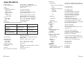
Specifications...................................50
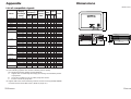
Appendix...........................................52
List of compatible signals ...............52
Dimensions.......................................53
Trademark acknowledgements ......54

ENGLISH-7
Preparation
6-ENGLISH
During a thunderstorm, do not touch the projector or the cable.
B Electric shocks can result.
Do not use the projector in a bath or shower.
B Fire or electric shocks can result.
Do not look into the lens while the projector is being used.
B Strong light is emitted from the projector’s lens. If you look directly into this
light, it can hurt and damage your eyes.
Do not bring your hands or other objects close to the air outlet port.
B Heated air comes out of the air outlet port. Do not bring your hands or
face, or objects which cannot withstand heat close to this port, otherwise
burns or damage could result.
Replacement of the lamp unit should only be carried out by a qualified
technician.
B The lamp unit has high internal pressure. It can easily become damaged if
struck against hard objects or dropped, and injury or malfunctions may
result.
When replacing the lamp, allow it to cool for at least one hour before
handling it.
B The lamp cover gets very hot, and contact with it can cause burns.
Before replacing the lamp, be sure to unplug the power cord from the
power outlet.
B Electric shocks or explosions can result if this is not done.
Caution
Do not set up the projector in humid or dusty places or in places where
the projector may come into contact with smoke or steam.
B Using the projector under such conditions may result in fire or electric
shocks.
When disconnecting the power cord, hold the plug, not the cord.
B If the power cord itself is pulled, the cord will become damaged, and fire,
short-circuits or serious electric shocks may result.
Always disconnect all cables before moving the projector.
B Moving the projector with cables still attached can damage the cables,
which could cause fire or electric shocks to occur.
Do not place any heavy objects on top of the projector.
B Failure to observe this may cause the projector to become unbalanced
and fall, which could result in damage or injury.
Do not short-circuit, heat or disassemble the battery or place it into
water or fire.
B Failure to observe this may cause the battery to overheat, leak, explode or
catch fire, and burns or other injury may result.
Do not do anything that might damage the power cord or the power
cord plug.
B Do not damage the power cord, make any modifications to it, place it near
any hot objects, bend it excessively, twist it, pull it, place heavy objects on
top of it or wrap it into a bundle.
B If the power cord is used while damaged, electric shocks, short-circuits or
fire may result.
B Ask an Authorised Service Centre to carry out any repairs to the power
cord that might be necessary.
Do not handle the power cord plug with wet hands.
B Failure to observe this may result in electric shocks.
Insert the power cord plug securely into the wall outlet.
B If the plug is not inserted correctly, electric shocks or overheating could
result.
B Do not use plugs which are damaged or wall outlets which are coming
loose from the wall.
Do not place the projector on top of surfaces which are unstable.
B If the projector is placed on top of a surface which is sloped or unstable, it
may fall down or tip over, and injury or damage could result.
Do not place the projector into water or let it become wet.
B Failure to observe this may result in fire or electric shocks.
Do not place liquid containers on top of the projector.
B If water spills onto the projector or gets inside it, fire or electric shocks
could result.
B If any water gets inside the projector, contact an Authorised Service
Centre.
Do not insert any foreign objects into the projector.
B Do not insert any metal objects or flammable objects into the projector or
drop them onto the projector, as doing so can result in fire or electric
shocks.
After removing the battery from the remote control unit, keep the
battery out of the reach of small children and infants.
B The battery can cause death by suffocation if swallowed.
B If the battery is swallowed, seek medical advice straight away.
Do not allow the + and - terminals of the battery to come into contact
with metallic objects such as necklaces or hairpins.
B Failure to observe this may cause the battery to leak, overheat, explode or
catch fire.
B Store the battery in a plastic bag and keep it away from metallic objects.
Insulate the battery using tape or similar before disposal.
B If the battery comes into contact with metallic objects or other batteries, it
may catch fire or explode.

ENGLISH-9
Preparation
8-ENGLISH
When inserting the battery, make sure the polarities (+ and -) are
correct.
B If the battery is inserted incorrectly, it may explode or leak, and fire, injury
or contamination of the battery compartment and surrounding area may
result.
Use only the specified battery.
B If an incorrect battery is used, it may explode or leak, and fire, injury or
contamination of the battery compartment and surrounding area may
result.
Do not put your weight on this projector.
B You could fall or the projector could break, and injury may result.
B Be especially careful not to let young children climb onto the projetor.
Disconnect the power cord plug from the wall outlet as a safety
precaution before carrying out any cleaning.
B Electric shocks can result if this is not done.
Ask an Authorised Service Centre to clean inside the projector at least
once a year.
B If dust is left to build up inside the projector without being cleaned out, it
can result in fire or problems with operation.
B It is a good idea to clean the inside of the projector before the season for
humid weather arrives. Ask your nearest Authorised Service Centre to
clean the projector when required. Please discuss with the Authorised
Service Centre regarding cleaning costs.
We are constantly making efforts to preserve and maintain a clean
environment. Please take non repairable units back to your dealer or a
recycling company.
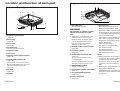
Card remote control unit
(TNQE239 x1)
Power cord for
Continental Europe
(K2CM3FZ00001 x 1)
Power cord for U.K.
(K2CT3FZ00001 x 1)
Lithium battery for
remote control unit
(CR2025 x1)
RGB signal cable [3.0 m
(9´10˝), K1HA15FA0002
x1]
Video/Audio cable [3.0
m (9´10˝),
K2KA2FA00001 x 1]
Accessories
Check that all of the accessories shown below have been included with your
projector.
ENTER
FREEZE
SHUTTER
INDEX
WINDOW
PROJECTOR
VOLUME D.ZOOM
STD
AUTO
SETUP
VIDEO
INPUT
POWER
RGB
MENU
Carrying bag (TPEP006
x1)

ENGLISH-11
Preparation
10-ENGLISH
About the screen
If the screen you are using is dirty, damaged or discoloured, attractive
projections cannot be obtained. Do not apply any volatile substances to the
screen, and do not let it become dirty or damaged.
Before carrying out cleaning and maintenance, be
sure to disconnect the power cord plug from the
wall outlet.
Wipe the cabinet with a soft, dry cloth.
If the cabinet is particularly dirty, soak the cloth in water with a small amount
of neutral detergent in it, squeeze the cloth very well, and then wipe the
cabinet. After cleaning, wipe the cabinet dry with a dry cloth.
If using a chemically-treated cloth, read the instructions supplied with
the cloth before use.
Do not wipe the lens with a cloth that is dusty or which produces lint.
If any dust or lint gets onto the lens, such dust or lint will be magnified and
projected onto the screen. Use a blower to clean any dust and lint from the
lens surface, or use a soft cloth to wipe off any dust or lint.
Precautions on handling
Cautions regarding transportation
Be sure to attach the lens cover before transporting the projector.
The projection lens is extremely susceptible to vibration and shocks. When
carrying the projector, use the accessory carrying bag.
When placing the projector inside the carrying bag, position it so
that the lens is facing upward.
Cautions regarding setting-up
Observe the following at all times when setting up the projector.
Avoid setting up in places which are subject to vibration or shocks.
If the projector is set up in locations with strong vibration, such as near a
motor, or if it is installed inside a vehicle or on board a ship, the projector
may be subjected to vibration or shocks which can damage the internal parts
and cause malfunctions or accidents. Accordingly, set up the projector in a
place which is free from such vibrations and shocks.
Do not set up the projector near high-voltage power lines or near
motors.
The projector may be subject to electromagnetic interference if it is set up
near high-voltage power lines or motors.
If installing the projector to the ceiling, ask a qualified technician to
carry out all installation work.
If the projector is to be suspended from the ceiling, you will need to purchase
the separate installation kit (Model No.: ET-PKC75). Furthermore, all
installation work should only be carried out by a qualified technician.
If using of this projector at high elevations (above 1400 m), consult
your dealer or Authorised Service Centre.
Special measures will be necessary to use this projector at high elevations,
so consult your dealer or Authorised Service Centre about preparations.
Failure to observe this may cause malfunctions.
Notes on use
In order to get the best picture quality
If outside light or light from indoor lamps is shining onto the screen, the
images projected will not have good contrast. Draw curtains or blinds over
any windows and turn off any fluorescent lights near the screen to prevent
reflection.
Do not touch the surfaces of the lens with your bare hands.
If the surface of the lens becomes dirty from fingerprints or anything else, this
will be magnified and projected onto the screen. Moreover, when not using
the projector, retract the lens and then cover it with the accessory lens cover.

ENGLISH-13
Preparation
12-ENGLISH
# Air outlet port
Do not cover this port.
WARNING
Do not bring your hands or other
objects close to the air outlet
port.
B Heated air comes out of the air
outlet port. Do not bring your
hands or face, or objects which
cannot withstand heat close to
this port, otherwise burns or
damage could result.
$ Remote control signal receptor
(page 18)
% Connector panel
(page 16)
& Power input socket (AC IN)
(page 24)
The accessory power cord is
connected here.
Do not use any power cord other
than the accessory power cord.
' MAIN POWER switch
(pages 24 and 25)
( Card remote control unit holder
(page 15)
) Front adjustable legs(L/R)
(page 24)
* Lamp unit holder
(page 45)
+ Security lock
This can be used to connect a
commercially-available theft-
prevention cable (manufactured
by Kensington). This security lock
is compatible with the Microsaver
Security System from
Kensington. Contact details for
this company are given below.
Kensington Technology Group
ACCO Brands Inc.
2855 Campus Drive
San Mateo, CA 94403 USA
Tel (650)572-2700
Fax (650)572-9675
http://www.kensington.com/
http://www.gravis.com/
NOTE:
B During projection of an image, the
cooling fan will operate, emitting
a small noise as it operates.
Turning the lamp on or off will
cause this noise to increase a
little.
B By using the OPTION2 menu to
set “LAMP POWER” to
STANDARD, the operating sound
of the fan can be reduced. (Refer
to page 37.)
Projector <Back and bottom>
Location and function of each part
# Projector control panel
(page 14)
$ Zoom ring
(page 25)
% Focus ring
(page 25)
& Air inlet ports
Do not cover these ports.
' Projection lens
( Lens cover
) Remote control signal receptor
(page 18)
* Leg adjuster buttons(L/R)
(page 24)
These buttons are used to unlock
the front adjustable legs. Press to
adjust the angle of tilt of the
projector.
+ Air filter
(page 44)
, Speaker
Projector <Top, right and front>
#
$
%
'
(
*
)
+
&
&
,
#$
%
&
'
*
+
)
(

ENGLISH-15
Preparation
14-ENGLISH
B The wireless remote control and the projector itself have the same control
buttons available.
# RGB INPUT indicator
(page 17)
This indicator shows whether a
signal is being input to the RGB
input connectors (RGB 1
IN/RGB2 IN). When an input
signal is detected, the indicator
illuminates.
$ LAMP indicator
(page 42)
This indicator illuminates when it
is time to replace the lamp unit. It
flashes if a circuit abnormality is
detected.
% TEMP indicator
(page 42)
This indicator illuminates if an
abnormally high temperature is
detected inside the projector or
surround it. If the temperature
rises above a certain level, the
power supply will be turned off
automatically and the indicator
will illuminate or flash.
& POWER button
(pages 24 and 25)
' Power indicator
(pages 24 and 25)
This indicator illuminates red
when the MAIN POWER switch is
turned on (standby mode), and
illuminates green when the power
is turned on and a picture starts
to be projected.
( AUTO SETUP button
(pages 17 and 25)
If this button is pressed while a
picture is being projected, the
projection settings will be
adjusted automatically in
accordance with the signal being
input. (“AUTO SETUP” will
appear on the screen during
adjustment.) If “AUTO KEYSTN”
in the OPTION1 menu is set to
“ON”, the angle of tilt of the
projector will be automatically
detected and adjusted in order to
correct any keystone distortion.
) Input select (INPUT, RGB,
VIDEO) buttons
(page 24)
<Projector control panel and remote control unit>
ENTER
FREEZE
SHUTTER
INDEX
WINDOW
PROJECTOR
VOLUME D.ZOOM
STD
AUTO
SETUP
VIDEO
INPUT
POWER
RGB
MENU
TEMP
LAMP
RGB INPUT
INPUTAUTO SETUP
POWER
STANDBY(R)
ON(G)
MENU ENTER
&
(
+
-
.
& ( )
% '$#
, + *
/
0
1
2
,
)
*
* ENTER button
(page 28)
This button is used to accept and
to activate items selected in the
on-screen menus.
+ Arrow (
FF
,
GG
,
II
and
HH
)
buttons
(page 28)
These buttons are used to select
and adjust items in the on-screen
menus.
, MENU button
(pages 26 and 28)
This button is used to display
menu screens. When a menu
screen is being displayed, it can
be used to return to a previous
screen or to clear the screen.
- FREEZE button
(page 29)
This button is used to
momentarily freeze the image so
that a still picture is displayed.
. VOLUME +/- buttons
These buttons are used to adjust
the volume of the sound output
by the projector’s built-in
speakers. Refer to page 26 for
details on how to adjust the
volume using the buttons on the
projector control panel.
/ INDEX WINDOW button
(page 39)
This button can be used to split
the image projection area into a
still image and a moving image.
0 D.ZOOM +/- buttons
(page 30)
These buttons are used to
enlarge certain portions of the
projected image.
1 STD (standard) button
(page 29)
This button is used to reset the
projector adjustment values to the
factory default settings.
2 SHUTTER button
(page 38)
This button is used to
momentarily turn off the picture
and sound.
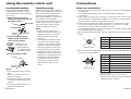
Storing the card
remote control unit
# Gently turn the projector
upside down.
$ Open the card remote control
unit holder.
% Place the remote control unit
inside.
& Close the card remote control
unit holder.
AU
T

ENGLISH-1716-ENGLISH
<Connector panel>
&
% ' ($#
# SERIAL connector
(pages 20, 21 and 40)
This connector is used to connect
a personal computer to the
projector in order to externally
control the projector. (RS-232C
compatible)
$ RGB1 IN connector
(pages 20 and 21)
This connector is used to input
RGB signals and YP
BP
R signals.
% RGB2 IN/RGB1 OUT connector
(pages 20, 21 and 36)
This connector is used to input or
output RGB signals and YP
BPR
signals. Use the RGB2 SELECT
item in the OPTION1 menu to
select whether you want input or
output with this conector.
& S-VIDEO IN connector
(pages 20 and 35)
This connector is used to input
signals from a S-VIDEO-
compatible equipment such as a
video deck. The connector is S1
signal compatible, and it
automatically switches between
16:9 and 4:3 aspect ratios in
accordance with the type of
signal being input.
' VIDEO IN jack
(page 20)
This jack is used to input video
signals from a video equipment
such as a video deck.
( AUDIO IN L-R jacks
(pages 20 and 21)
Only one audio system circuit is
available for the AUDIO IN L-R
jacks, so if you wish to change
the audio input source, you will
need to remove and insert the
appropriate plugs.
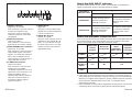
About the RGB INPUT indicator
The RGB input indicator can be used to check whether an RGB/YP
BPR
signal is being input. Refer to the table below for details.
RGB INPUT
indicator status
Power supply status
On (projecting)Standby
A signal is being input to
either the RGB1 IN or
RGB2 IN connector.
A signal is being input to
the connector selected
using the input select
buttons.
No signal is being input to
either the RGB1 IN or
RGB2 IN connector.
No signal is being input to
the connector selected
using the input select
buttons.
Illuminated
Switched off
About the automatic setup function
If you press the AUTO SETUP button, the items given in the table below will
be set automatically. The setting details change according to the signal
which is being input. Refer to the table below for details.
VIDEO/
S-VIDEO
YP
BPR
Clock is
100 MHz or
higher
Other
Horizontal/
vertical
position
Dot clock/
clock phase
Auto RGB
input
select/auto
YP
BPR select
Automatic
keystone
correction
Yes
Yes
Yes
Yes
Yes No
NOTE:
B If the edges of the projected picture are indistinct, or if a dark picture is
being projected, the automatic setup processing may stop automatically
before it is complete. If this happens, project a different picture and then
press the AUTO SETUP button once more, or make the above
adjustments manually.
B If you would like to make further adjustments to the picture, use the menu
commands which are listed on page 26 and subsequent pages.

ENGLISH-19
Preparation
18-ENGLISH
Inserting the battery
Insert the lithium battery which is
supplied with the remote control
unit, making sure that the polarities
are correct.
# While pushing the battery
holder tab to the right, pull out
the battery holder.
$ Insert the battery into the
battery holder so that the +
side is facing upward.
% Insert the battery holder.
NOTE:
B Do not drop the remote control
unit.
B Keep the remote control unit
away from liquids.
B Remove the battery if not using
the remote control unit for long
periods.
B Use only CR2025 batteries as
replacement batteries.
Using the remote control unit
Operating range
If the remote control unit is held so
that it is facing directly in front of the
front or rear remote control signal
receptors, the operating range is
within approximately 7 m (23´) from
the surfaces of the receptors.
Furthermore, the remote control unit
can be operated from an angle of
±30 ° to the left or right and ±15 °
above or below the receptors.
NOTE:
B If there are any obstacles in
between the remote control unit
and the receptors, the remote
control unit may not operate
correctly.
B If strong light is allowed to shine
onto the remote control signal
receptor, correct remote control
operation may not be possible.
Place the projector as far away
from light sources as possible.
B If facing the remote control unit
toward the screen to operate the
projector, the operating range of
the remote control unit will be
limited by the amount of light
reflection loss caused by the
characteristics of the screen
used.
Push the tab
Pull out
Connections
Notes on connections
B Read the instruction manual for each system component carefully before
connecting it.
B Turn off the power supply for all components before making any
connections.
B If the cables necessary for connecting a component to the system are not
included with the component or available as an option, you may need to
fashion a cable to suit the component concerned.
B If there is a lot of jitter in the video signal which is input from the video
source, the picture on the screen may flicker. In such cases, it will be
necessary to connect a TBC (time base corrector).
B It may not be possible to connect some types of computer. Refer to the list
of compatible signals on page 52.
B The pin layout and signal names for the S-VIDEO IN connector are shown
below.
Pin No. Signal
#
Earth (Luminance signal)
Earth (Colour signal)
Luminance signal
Colour signal
$
%
&
B The pin layout and signal names for the RGB/YPBPR (RGB1 IN/RGB2 IN)
connector are shown below.
Pin No. Signal
#
R/P
R
G/G·SYNC/Y
B/P
B
SDA
$
%
.
/
HD/SYNC
0
VD
1
SCL
Pin + is spare.
Pins &–*, , and - are for earth.
Pins . and 1 functions are only valid when
supported by the computer
#$
%&
External view
-1
#'
,(
External view
Match the “+”
surface of the
battery with the
“+” marked side of
the battery holder.
Back side

ENGLISH-21
Preparation
20-ENGLISH
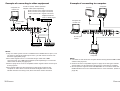
DVD player
Example of connecting to video equipment
D-sub 15 (male) - BNC5 (female)
adapter cable (sold separately)
Red (connect to P
R signal connector)
Blue (connect to PB signal connector)
Green (connect to Y signal connector)
Digital broadcast
tuner or DVD player
D-sub 9-pin
(male)
Video deck
NOTE:
B Only one audio system circuit is available for the AUDIO IN L-R jacks, so if
you wish to change the audio input source, you will need to remove and
insert the appropriate plugs.
B If the video signal source is connected using a cable with a BNC
connector plug, use a BNC/RCA adapter (sold separately) to convert the
cable end to an RCA plug-type jack.
B Refer to page 52 for a list of compatible YP
BPR signals which can be input
to the projector.
B If the signal cables are disconnected or if the power supply for the
computer or video deck is turned off while the digital zoom or index
window functions are being used, these functions will be cancelled.
D-sub 9-pin
(male)
Computer
Computer for
control use
Computer for
control use
Computer
NOTE:
B It is better to shut down the computer before turning off the MAIN POWER
switch of the projector.
B Refer to the list of compatible signals on page 52 for the types of RGB
signals which can be input to the projector by connecting a computer.
B Do not input the signal to the RGB2 IN/RGB1 OUT connector when the
RGB2 SELECT item in the OPTION1 menu is set to OUTPUT. (Refer to
page 36.)
Example of connecting to computer
Monitor

ENGLISH-23
Preparation
22-ENGLISH
Setting-up
Projection methods
The projector can be set up so that any one of the following four projection
methods are used. Select whichever projection method matches the setting-
up method. (The projection method can be set from the OPTION2 menu.
Refer to page 37 for details.)
FRONT/REAR
FRONT
REAR
(Factory default setting)
NOTE:
B You will need to purchase the separate ceiling bracket (ET-PKC75) when
using the ceiling installation method.
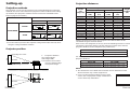
Projector position
DESK/CEILING
DESK CEILING
H1
L
L
SH
SW
TEMP
LAMP
RGB INPUT
INPUTAUTO SETUP
POWER
STANDBY(R)
ON(G)
MENU ENTER
57 mm
L: Projection distance
SH: Image height
SW:Image width
H1: Distance from centre
of lens to bottom edge
of projected image
Top edge of screen
Screen
Bottom edge of screen
Screen
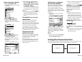
Projection distances
Setting-up dimensions which are not given in the above table can be
calculated using the formulas below.
If the screen size (diagonal) is SD (m), then the following formula is used to
calculate the projection distance for the wide lens position (LW) and the
projection distance for the telephoto lens position (LT).
For 16:9 aspect ratios, the following formula can be used to calculate the
projection distance.
NOTE:
B The dimensions in the table above and the values obtained from the
above formulas may contain slight errors.
B If you use the projection distance for the 16:9
screen, the 4:3 projection image overflows the
screen at the top and bottom.
0.84 m(33˝) 1.1 m(3´7˝) 1.1 m(3´7˝) 0.08 m(3-1/8˝)
1.02 m(40˝) 1.2 m(3´11˝) 1.4 m(4´7˝) 1.2 m(3´11˝) 1.4 m(4´7˝) 0.09 m(3-17/32˝)
1.27 m(50˝) 1.5 m(4´11˝) 1.7 m(5´6˝) 1.5 m(4´11˝) 1.8 m(5´10˝) 0.11 m(4-5/16˝)
1.52 m(60˝) 1.8 m(5´10˝) 2.1 m(6´10˝) 1.8 m(5´10˝) 2.1 m(6´10˝) 0.14 m(5-1/2˝)
1.78 m(70˝) 2.1 m(6´10˝) 2.4 m(7´10˝) 2.1 m(6´10˝) 2.5 m(8´2˝) 0.16 m(6-9/32˝)
2.03 m(80˝) 2.4 m(7´10˝) 2.8 m(9´2˝) 2.4 m(7´10˝) 2.9 m(9´6˝) 0.18 m(7-1/16˝)
2.29 m(90˝) 2.7 m(8´10˝) 3.2 m(10´5˝) 2.8 m(9´2˝) 3.2 m(10´5˝) 0.20 m(7-27/32˝)
2.54 m(100˝) 3.0 m(9´10˝) 3.5 m(11´5˝) 3.0 m(9´10˝) 3.6 m(11´9˝) 0.22 m(8-21/32˝)
3.05 m(120˝) 3.6 m(11´9˝) 4.2 m(13´9˝) 3.7 m(12´1˝) 4.3 m(14´1˝) 0.26 m(10-7/32˝)
3.81 m(150˝) 4.5 m(14´9˝) 5.3 m(17´4˝) 4.6 m(15´1˝) 5.4 m(17´8˝) 0.33 m
(12-31/32˝)
5.08 m(200˝) 6.0 m(19´8˝) 7.1 m(23´3˝) 6.1 m(20´) 7.3 m(23´11˝) 0.44 m(17-5/16˝)
6.35 m(250˝) 7.5 m(24´7˝) 8.9 m(29´2˝) 7.6 m(24´11˝) 9.1 m(29´10˝) 0.55 m(21-5/8˝)
7.62 m(300˝) 9.0 m(29´6˝) 10.7 m(35´1˝) 9.2 m(30´2˝) 11.0 m(36´1˝) 0.66 m
(25-31/32˝)
Wide
(LW)
Telephoto
(LT)
Projection distance (L)
PT-LC75E PT-LC55E
Height
position
(H1)
Wide
(LW)
Telephoto
(LT)
Screen
size
(diagonal)
PT-LC75E PT-LC55E
LW=0.030xSD/0.0254-0.037 LW=0.031xSD/0.0254-0.038
LW=0.036xSD/0.0254-0.037 LW=0.037xSD/0.0254-0.038
PT-LC75E PT-LC55E
LW=0.032xSD/0.0254-0.037 LW=0.033xSD/0.0254-0.038
LW=0.039xSD/0.0254-0.037 LW=0.040xSD/0.0254-0.038

Basic Operation
ENGLISH-2524-ENGLISH
Turning off the power
# Hold down the POWER button for at least 0.5 seconds or press the
POWER button twice to turn off the power.
The lamp unit will switch off and the picture will stop being projected. (The
power indicator on the projector will illuminate orange.)
$ Wait until the power indicator on the projector illuminates red (until
the cooling fan stops).
Do not in any way cut power to the projector while the cooling fan is still
operating. Be careful not to switch off the MAIN POWER switch of the
projector, unplug the power cord from the electrical outlet or turn off in-line
switches such as tabletop power switches.
% Press the MAIN POWER switch to the “O” side to turn off the power.
NOTE:
B After the power is turned off, the lamp unit will take some time to cool
down. If you turn the power back on again before the lamp unit has cooled
down, the lamp unit may not turn on straight away, but it will turn on
automatically after a short period. (During this time, the power indicator on
the projector will flash orange.)
B When the projector is in standby mode (the power indicator on the
projector is illuminated red), the projector will still draw a maximum 2 W of
power, even when the cooling fan has stopped.
B If the MAIN POWER switch is accidentally turned off while the projector is
being used, the lamp unit may not turn on straight away after the power is
turned back on. In such cases, the lamp unit will turn back on
automatically after a short period. (During this time, the power indicator on
the projector will flash green.)
B A tinkling sound may be heard while the power indicator is turned off, but
this is not a sign of a malfunction.
Starting to use
Turning on the power
Please ensure that all preparations have been completed before turning on
the power. (Refer to pages 19 – 23.)
S-VIDEO
VIDEO
RGB2
RGB1
RGB2
RGB1
S-VIDEO
VIDEO
INPUT
RGB
VIDEO
$%
ENTER
FREEZE
SHUTTER
INDEX
WINDOW
PROJECTOR
VOLUME D.ZOOM
STD
AUTO
SETUP
VIDEO
INPUT
POWER
RGB
MENU
INPUTAUTO SETUP
POWER
STANDBY(R)
ON(G)
MENU ENTER
ENTER
FREEZE
SHUTTER
INDEX
WINDOW
PROJECTOR
VOLUME D.ZOOM
STD
AUTO
SETUP
VIDEO
INPUT
POWER
RGB
MENU
INPUTAUTO SETUP
POWER
STANDBY(R)
ON(G)
MENU ENTER
# Remove the lens cover.
$ Connect the accessory power cord.
% Press the MAIN POWER switch to
the “|” side to turn on the power.
The power indicator on the projector
will illuminate red.
& Press the POWER button.
The power indicator on the projector
will flash green. After a short period,
the indicatore will illuminate green, and
a picture will be projected.
' Turn on the power of all connected
devices.
Start the Play function a device such
as a DVD player.
( Press the input select (INPUT, RGB,
VIDEO) button to select the input
signal.
The input signal selected will change
as shown at below each time an input
select button is pressed.
) While pressing the adjuster buttons,
adjust the forward/back angle of tilt
of the projector.
ENTER
FREEZE
SHUTTER
INDEX
WINDOW
PROJECTOR
VOLUME D.ZOOM
STD
AUTO
SETUP
VIDEO
INPUT
POWER
RGB
MENU
INPUTAUTO SETUP
POWER
STANDBY(R)
ON(G)
MENU ENTER
* Press the AUTO SETUP button to
initiate automatic positioning.
When keystone distortion is not
corrected, carry out keystone
correction as described on page 31.
+ Turn the focus/zoom ring to adjust
the projected image focus and size.
Zoom
Focus

ENGLISH-27
Basic Operation
26-ENGLISH
When an S-VIDEO/VIDEO signal
is being input
PICTURE
PICTURE MODE STANDARD
COLOR 32
TINT 32
BRIGHT 32
CONTRAST 32
SHARPNESS 0
COLOR TEMP. STANDARD
W-BAL R 32
W-BAL G 32
W-BAL B 32
SIGNAL MODE SVGA
STANDARD
SELCT ADJ ESC
PICTURE
PICTURE MODE STANDARD
COLOR 32
TINT 32
BRIGHT 32
CONTRAST 32
SHARPNESS 4
COLOR TEMP. STANDARD
TV-SYSTEM AUTO1
STANDARD
SELCT ADJ ESC
PICTURE menu (page 32)
When an RGB/YPBPR signal is
being input
When an S-VIDEO/VIDEO signal
is being input
POSITION
H-POSI 64
V-POSI 32
DOT CLK 32
CLK PHASE 16
ASPECT 4:3
RESIZING ON
STANDARD
SELCT ENTER ESC
POSITION
H-POSI 32
V-POSI 16
ASPECT 4:3
RESIZING ON
STANDARD
SELCT ENTER ESC
POSITION menu (page 34)
When an RGB/YP
BPR
signal is
being input
On-screen menus
Menu screens
The various settings and adjustments for this projector can be carried out by
selecting the operations from on-screen menus.
The general arrangement of these menus is shown below.
MAIN MENU
OPTION2 menu (page 36)
LANGUAGE menu (page 38)
SHUTTER function
(page 38)
NOTE:
B Keystone distortion of the on-screen display will not be corrected.
MENU
KEYSTONE
PICTURE
POSITION
INDEX WINDOW
SHUTTER
AUDIO
LANGUAGE
OPTION1
OPTION2
SELCT ENTER
OPTION2
BACK COLOR BLUE
FRONT/REAR FRONT
DESK/CEILING DESK
LAMP POWER HIGH
LAMP RUNTIME 10H
FUNC 1 INDEX
SELCT ADJ ESC
LANGUAGE ENGLISH
ENGLISH
DEUTSCH
FRANÇAIS
ESPAÑOL
ITALIANO
SELCT ENTER ESC
Keystone correction
(page 31)
OPTION1
OSD ON
AUTO KEYSTN ON
AUTO Y•PB•PR ON
AUTO RGB IN ON
RGB2 SELECT INPUT
RGB FORMAT Y•PB•PR
SELCT ADJ ESC
OPTION1 menu (page 36)
INDEX WINDOW function
(page 39)
Volume adjustment
Press the ENTER button, and
then press the I and H
buttons to adjust the volume.

ENGLISH-29
Basic Operation
28-ENGLISH
Returning a setting to
the factory default
If you press the STD (standard)
button on the remote control unit,
you can return settings to the
factory default settings. However,
the operation of this function varies
depending on which screen is being
displayed.
B When a menu screen is being
displayed
All items displayed will be returned
to their factory default settings,
“STD” will be displayed in the top-
right screen and the bar scale will
appear white.
NOTE:
B You can also select STANDARD
from the menu screen and then
press the ENTER button.
B When an individual adjustment
screen is being displayed
Only the item displayed will be
returned to the factory default
setting, and the bar scale will
appear white.
NOTE:
B Triangle symbols above and
below a menu bar indicate the
factory default setting. Items
which do not have these triangle
symbols cannot be returned to
the factory default setting.
Indicates the standard factory
default setting
Indicates the current adjustment
value
B The positions of triangle symbols
vary depending on the type of
signal being input.
Menu operation guide
# Press the MENU button.
The MAIN MENU screen will be
displayed.
$ Press the
FF
or
GG
arrow
buttons to select an item.
Selected items will be displayed
in blue.
% Press the ENTER button to
accept the selection.
The selected menu screen or
adjustment screen will then be
displayed.
(Example: PICTURE menu)
MENU
KEYSTONE
PICTURE
POSITION
INDEX WINDOW
SHUTTER
AUDIO
LANGUAGE
OPTION1
OPTION2
SELCT ENTER
MENU
KEYSTONE
PICTURE
POSITION
INDEX WINDOW
SHUTTER
AUDIO
LANGUAGE
OPTION1
OPTION2
SELCT ENTER
PICTURE
PICTURE MODE STANDARD
COLOR 32
TINT 32
BRIGHT 32
CONTRAST 32
SHARPNESS 4
COLOR TEMP. STANDARD
TV-SYSTEM AUTO1
STANDARD
SELCT ADJ ESC
& Press the
FF
or
GG
buttons to
select an item, and then press
the
II
or
HH
buttons to change
or adjust the setting.
An individual adjustment screen
such as the one shown below will
be displayed for bar-scale items.
The bar scale will turn green
when any adjustment changes
the setting from the factory set
value.
Unavailable on-screen
menu items
This projector has unadjustable
items and unusable functions
depending on the signal being input.
When an item cannot be adjusted or
a function cannot be used, the
corresponding on-screen menu
display does not appear, and the
item or function will not work even if
the ENTER button is pressed.
Returning to the
previous screen
If you press the MENU button while
a menu screen is being displayed,
the display will return to the
previous screen.
If you press the MENU button while
the MAIN MENU screen is being
displayed, the MAIN MENU screen
will be cleared.
BRIGHT 32
PICTURE STD
PICTURE MODE STANDARD
COLOR 32
TINT 32
BRIGHT 32
CONTRAST 32
SHARPNESS 4
COLOR TEMP. STANDARD
TV-SYSTEM AUTO1
STANDARD
SELCT ENTER ESC
BRIGHT 32
Using the freeze function
The picture will alternate between a still picture and a moving picture each
time the FREEZE button on the remote control unit is pressed.
Still picture Moving picture

ENGLISH-31
Basic Operation
30-ENGLISH
Using the D.ZOOM (digital zoom)
function
This function lets you enlarge a
single section of the picture.
Furthermore, the spot display mode
which is used to select the section
which is to be enlarged can also be
used when making presentations.
# Press a D.ZOOM +/- button.
The projector will change to spot
display mode.
$ Use the
FF
,
GG
,
II
and
HH
buttons to move the spot to the
section which you would like to
enlarge, and then press the
ENTER button.
The area around the spot will
then be enlarged to twice the
normal size.
% Use the D.ZOOM +/- buttons to
change the enlargement ratio.
The enlargement ratio can be
changed within the range of x1 to
x2, in steps of 0.1.
NOTE:
B When RGB signals are being
input, the enlargement ratio can
be changed within the range of
x1 to x3.
& Press the MENU button to
return to the normal screen.
The projector will not return to
spot display mode at this time. To
return to spot display mode, clear
the enlarged picture display from
the screen and then press a
D.ZOOM +/- button again.
NOTE:
B This function can only be used
when using the remote control
unit.
B If the type of signal being input
changes while the digital zoom
function is being used, the digital
zoom function will be cancelled.
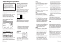
Correcting keystone distortion
Keystone distortion is corrected automatically when the projector’s automatic
setup function is used, but this correction will not apply if the screen itself is
tilted. In such cases, you can correct the keystone distortion manually with
the following procedure.
# Select “KEYSTONE” from the MAIN MENU screen, and then press the
ENTER button.
$ Press the
II
or
HH
buttons to correct the keystone distortion.
Picture condition Operation
Press the
HH
button.
Press the
II
button.
% Press the MENU button to return to the previous screen.
NOTE:
B If you press the AUTO SETUP button after correcting the keystone
distortion manually, the automatic keystone correction function will operate
and the corrected picture will return to its previous incorrect condition. To
prevent this from happening, you can set “AUTO KEYSTN” in the
OPTION1 menu to “OFF”.
B Keystone distortion can be corrected to ±30° of the angle of tilt for the
projector. However, the greater the correction amount, the more the
picture quality will deteriorate, and the harder it will become to achieve a
good level of focus. To obtain the best picture quality, set up the projector
and screen in such a way that the amount of keystone correction required
is as minimal as possible.
B The picture size will also change when correction of keystone distortion is
carried out.

I button to make the picture
darker. (Adjust the BRIGHT setting
first if required before adjusting the
CONTRAST setting.)
SHARPNESS
Press the H button to make the
picture details sharper, and press
the I button to make the picture
details softer.
Colour Hue Setting
(color temperature)
This is used to adjust the white
areas of the picture if they appear
bluish or reddish.
TV SYSTEM
(S-VIDEO/VIDEO only)
AUTO1
The projector automatically
distinguishes between NTSC/NTSC
4.43/PAL/SECAM signals.
AUTO2
The projector automatically
distinguishes between NTSC/PAL-
M/PAL-N signals.
NOTE:
B This should normally be set to
“AUTO1” or “AUTO2”. If the
signal is of such poor quality that
the correct format cannot be
automatically distinguished,
change the setting manually to
the required TV system.
WHITE BALANCE R/G/B
(RGB only)
This is used to adjust the white
areas of the picture if they appear
colourised.
Press the I button to make the
selected colour lighter.
Press the H button to make the
selected colour stronger.
SIGNAL MODE
(RGB/YPBPR only)
This displays the type of signal
which is currently being projected.
Refer to the table on page 52 for
details on each type of signal.
Use the F and G buttons on the
projector or remote control unit to
select an item, and then use the I
and H buttons to change the setting
for that item.
For items with bar scales, press the
ENTER button or the I or H
buttons to display the adjustment
screen, and then use the I or H
buttons to make the adjustment.
When an RGB/YP
BP
R signal is
being input
When an S-VIDEO/VIDEO signal is
being input
PICTURE MODE
Select the picture mode that best
matches the image source and
room conditions.
The mode best used in dark rooms
is NATURAL. For rooms having
regular lighting conditions in use,
select STANDARD. For
exceptionally bright rooms, use
DYNAMIC.
COLOR
(S-VIDEO/VIDEO/YP
BPR
only)
Press the H button to make the
colour more vivid in tone, and press
the I button to make the colour
more pastel in tone.
TINT
(NTSC/NTSC 4.43/YPBPR only)
This adjusts the flesh tones in the
picture. Press the H button to make
flesh tones more greenish, and
press the I button to make the
flesh tones more reddish.
BRIGHT
This adjusts the darker areas (black
areas) in the picture. Press the H
button if dark areas are too solid (for
example, if hair is difficult to see),
and press the I button if black
areas are too light (grey rather than
black).
CONTRAST
This adjusts the contrast of the
picture. Press the H button to make
the picture brighter, and press the
ENGLISH-33
Basic Operation
32-ENGLISH
Adjusting the picture
TV-SYSTEM AUTO1
[
AUTO2
[
NTSC
[
NTSC4.43
[
PAL
[
PAL-M
[
PAL-N
[
SECAM
COLOR TEMP. STANDARD
[
HIGH
[
LOW
PICTURE MODE STANDARD
[
DYNAMIC
[
NATURAL
PICTURE
PICTURE MODE STANDARD
COLOR 32
TINT 32
BRIGHT 32
CONTRAST 32
SHARPNESS 0
COLOR TEMP. STANDARD
W-BAL R 32
W-BAL G 32
W-BAL B 32
SIGNAL MODE SVGA
STANDARD
SELCT ADJ ESC
PICTURE
PICTURE MODE STANDARD
COLOR 32
TINT 32
BRIGHT 32
CONTRAST 32
SHARPNESS 4
COLOR TEMP. STANDARD
TV-SYSTEM AUTO1
STANDARD
SELCT ADJ ESC

AUTO
(S-VIDEO only)
When an S1 video signal is input to
the S-VIDEO terminal, the aspect
ratio is changed automatically to
project a 16:9 picture.
4:3
The input signal is projected without
change.
16:9
The picture is compressed to a ratio
of 16:9 and projected.
S4:3
The size of the input signal is
compressed to 75% and projected.
(This is useful for projecting a
picture with a 4:3 aspect ratio onto a
16:9 screen.)
S1 video signals
B
S1 video signals are a type of video
signal with an aspect ratio of 16:9
which include a detector signal. This
detector signal is output by some
sources such as wide-vision video
decks. If the AUTO setting above is
selected, this projector will recognise
the detector signal and automatically
switch the aspect ratio to 16:9 in
order to project the picture.
NOTE:
B
This projector is equipped with an
aspect ratio selection function.
However, if a mode which does not
match the aspect ratio of the input
signal is selected, it may affect the
quality of viewing of the original
picture. Keep this in mind when
selecting the aspect ratio.
B
If using this projector in places such
as cafes or hotels with the aim of
displaying programmes for viewing
for a commercial purpose or for
public presentation, note that if the
aspect ratio (16:9) selection function
is used to change the aspect ratio of
the screen picture, you may be
infringing the rights of the original
copyright owner for that programme
under copyright protection laws.
B
If a normal (4:3) picture which was
not originally intended for wide-
screen viewing is projected onto a
wide screen, distortion may occur
around the edges of the picture so
that part of the picture is no longer
visible. Such programmes should be
viewed in 4:3 mode to give proper
consideration to the aims and
intentions of the original programme’s
creator.
RESIZING
This should normally be set to “ON”.
(This setting is only for signals
which have lower resolutions than
the LCD panels. Refer to page 52
for details.)
ON
The pixel resolution of the input
signal is converted to the same
resolution as the LCD panels before
being projected. For signals with
lower resolutions, gaps in the pixels
are automatically interpolated into
the picture before it is projected.
This may sometimes cause
problems with the quality of the
picture.
OFF
The picture signal is projected at its
original resolution, with no pixel
conversion. The projected picture
will be smaller than normal, so
adjust the zoom setting or move the
projector forwards or backwards to
adjust the picture size if necessary.
Use the F and G buttons on the
projector or remote control unit to
select an item, and then use the I
and H buttons to change the setting
for that item.
For items with bar scales, press the
ENTER button or the I or H
buttons to display the adjustment
screen, and then use the I or H
buttons to make the adjustment.
When an RGB/YP
BPR signal is
being input
When an S-VIDEO/VIDEO signal is
being input
HORIZONTAL POSITION
Press the I button to move the
picture to the left, and press the H
button to move the picture to the right.
VERTICAL POSITION
Press the I button to move the
picture down, and press the H
button to move the picture up.
DOT CLOCK
(RGB only)
Periodic striped pattern interference
(noise) may occur when a striped
pattern such as the one below is
projected. If this happens, use the
I and H buttons to adjust so that
any such noise is minimised.
CLOCK PHASE
(RGB only)
Adjust the DOT CLOCK setting first
before carrying out this adjustment.
Use the I and H buttons to adjust
so that the noise level is least
noticeable.
NOTE:
B
If signals with a dot clock frequency
of 100 MHz or higher are being input,
interference may not be completely
eliminated when the DOT CLOCK
and CLOCK PHASE adjustments are
carried out.
ASPECT
This setting is only valid for S-
VIDEO/VIDEO signals and YPBPR
signals in 525i (480i), 525p (480p)
and 625i format.
ENGLISH-35
Basic Operation
34-ENGLISH
Adjusting the position
POSITION
H-POSI 64
V-POSI 32
DOT CLK 32
CLK PHASE 16
ASPECT 4:3
RESIZING ON
STANDARD
SELCT ENTER ESC
POSITION
H-POSI 32
V-POSI 16
ASPECT 4:3
RESIZING ON
STANDARD
SELCT ENTER ESC
ASPECT AUTO
[
4:3
[
16:9
[
S4:3
When the input signal is RGB, first
press AUTO SETUP button to
initiate automatic positioning.
If the optimum setting is not
obtained when AUTO SETUP is
carried out, adjust by the following
procedure.

Use the F and G buttons on the
projector or remote control unit to
select an item, then press the I or
H buttons to change the setting.
OSD
ON
The signal name is displayed in the
top-right corner of the screen when
the input signal is changed.
OFF
Use this setting when you do not
want the signal name to be
displayed.
AUTO KEYSTN
This should normally be set to ON.
ON
During automatic setup, the angle of
tilt of the projector is detected and
keystone distortion is corrected
automatically.
OFF
Use this setting when you do not
want automatic keystone correction
to be carried out during automatic
setup, such as when the screen
itself is at an angle.
AUTO Y·PB·PR
AUTO RGB IN
This should normally be set to ON.
ON
During automatic setup, the
projector selects whichever one of
the RGB1 IN or RGB2 IN
connectors has a signal being input,
and uses that signal for projection.
(If a picture is being projected, the
signal source is not automatically
changed.)
OFF
Use this setting when you do not
want the signal source to be
changed automatically during
automatic setup.
RGB2 SELECT
This setting is used to select the
function of the RGB2 IN/RGB1 OUT
connector.
RGB FORMAT
This setting is only valid when an
HDTV signal is being input and
“AUTO Y·PB·PR” is set to OFF.
BACK COLOR
This sets the colour which is
projected onto the screen when no
signal is being input to the projector.
FRONT/REAR
This setting should be changed in
accordance with the projector
setting-up method.
Set to “FRONT” when using a
normal reflective screen with the
projector positioned in front of the
screen, and set to “REAR” when
using a translucent screen with the
projector positioned behind the
screen.
DESK/CEILING
This setting should be changed in
accordance with the projector
setting-up method.
Set to “DESK” when setting up the
projector on a desk or similar, and
set to “CEILING” when suspending
the projector from the ceiling using
the ceiling bracket which is sold
separately.
LAMP POWER
This setting changes the lamp
brightness. When set to
“STANDARD”, the luminance of the
lamp is reduced, but the projector
uses less power, and the operating
noise is also reduced. This can help
to extend the lamp’s operating life. If
using the projector in small rooms
where high luminance is not
required, it is recommended that
you set the LAMP POWER to
“STANDARD”.
LAMP TIME
This setting displays the usage time
for the lamp unit which is currently
being used.
NOTE:
B The lamp’s operating life varies
depending on the usage
conditions (such as the LAMP
POWER setting and the number
of times the power is turned on
and off).
ENGLISH-37
Advanced Operation
36-ENGLISH
Option settings
AUTO Y·PB·PR
HDTV60
HDTV50
Other
Input
signal
RGB or YP
BP
R is
selected automatically
depending on the
synchronising signal
status.
ON OFF
RGB
format
setting
becomes
valid
RGB or YPBPR is
selected
automatically
depending on the
synchronising
signal status.
OPTION1
OSD ON
AUTO KEYSTN ON
AUTO Y•PB•PR ON
AUTO RGB IN ON
RGB2 SELECT INPUT
RGB FORMAT Y•PB•PR
SELCT ADJ ESC
RGB2 SELECT INPUT
[
OUTPUT
RGB FORMAT RGB
[
Y•PB•PR
BACK COLOR BLUE
[
BLACK
FRONT/REAR FRONT
[
REAR
DESK/CEILING DESK
[
CEILING
LAMP POWER HIGH
[
STANDARD
OPTION2
BACK COLOR BLUE
FRONT/REAR FRONT
DESK/CEILING DESK
LAMP POWER HIGH
LAMP RUNTIME 10H
FUNC 1 INDEX
SELCT ADJ ESC

ENGLISH-39
Advanced Operation
38-ENGLISH
Changing the display language
Indicates the language which is
currently set
Use the F and G buttons on the
projector or remote control unit to
select a language, then press the
ENTER button to accept the setting.
LANGUAGE ENGLISH
ENGLISH
DEUTSCH
FRANÇAIS
ESPAÑOL
ITALIANO
SELCT ENTER ESC
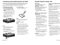
Using the shutter function
The shutter function can be used to momentarily turn off the picture and
sound from the projector when the projector is not being used for short
periods of time, such as during breaks in meetings or when carrying out
preparation. The projector uses less power in shutter mode than it does in
normal projection mode.
# Press the SHUTTER button on the remote control unit.
You can also select SHUTTER from the MAIN MENU screen and then
press the ENTER button.
$ Press any button on either the projector or remote control unit to
return to normal operating mode.
Using the INDEX WINDOW function
This function lets you store a picture which is being projected into memory,
so that you can display a still picture and a moving picture on the screen.
# Press the INDEX WINDOW button.
You can also select INDEX WINDOW from
the MAIN MENU screen and then press the
ENTER button.
NOTE:
B The aspect ratio of the screen changes and
the image is vertically elongated in
comparison to a normal image.
$ Use the F and G buttons to select a screen size.
The screen size can be chosen from 3 options.
Still
picture
Moving
picture
Still
picture
Moving
picture
Still
picture
Moving
picture
Still
picture
Moving
picture
Still
picture
Moving
picture
Moving
picture
Still
picture
% Use the
II
and
HH
buttons to switch between the still picture screen
(left) and moving picture screen (right).
& Press the ENTER button to store the picture in memory.
NOTE:
B When the screen size is changed, the picture’s aspect ratio will also
change. Make sure that you fully understand the notes on ASPECT which
are given on page 35 before using the index window function.
B When steps $ and % are carried out, the memory will be reset and a new
picture will be stored in memory.
FUNC 1
This assigns a function to the F1
button of the ET-RM100 wireless
remote control unit (sold
separately).
INDEX
B Functions in the same way as the
INDEX WINDOW button on the
accessory card remote control
unit. (page 39)
KEYSTONE
B Functions in the same way as
when “KEYSTONE” is selected
from the MAIN MENU screen.
(page 31)
FUNC1 INDEX
[
KEUSTONE
Page is loading ...
Page is loading ...
Page is loading ...
Page is loading ...
Page is loading ...
Page is loading ...
Page is loading ...
Page is loading ...
-
 1
1
-
 2
2
-
 3
3
-
 4
4
-
 5
5
-
 6
6
-
 7
7
-
 8
8
-
 9
9
-
 10
10
-
 11
11
-
 12
12
-
 13
13
-
 14
14
-
 15
15
-
 16
16
-
 17
17
-
 18
18
-
 19
19
-
 20
20
-
 21
21
-
 22
22
-
 23
23
-
 24
24
-
 25
25
-
 26
26
-
 27
27
-
 28
28


Panasonic PTLC75E Operating instructions
- Category
- Data projectors
- Type
- Operating instructions
- This manual is also suitable for
Ask a question and I''ll find the answer in the document
Finding information in a document is now easier with AI
Related papers
-
Panasonic PT-LC75E User manual
-
-
Panasonic PT-AE100U User manual
-
Panasonic PT-D10000U User manual
-
Panasonic PT-LC80E User manual
-
-
-
Panasonic PTLB30E User manual
-
-
Other documents
-
Sony PK-R1FL User manual
-
 Luce PT-L6600E User manual
-
Technicolor - Thomson PT-AE2000E User manual
-
Philips PT-LB51SU User manual
-
Axis BA2218 Installation guide
-
LG BA850 User manual
-
LG BX503B User manual
-
 Commercial Electric 5003-WH Operating instructions
-
Sharp NV4 User manual
-
 Vidikron Projector 60 User manual


