Leviton Inform User guide

Type
User guide

Sure, here is a brief product information for Leviton Inform:

Leviton Inform: The Leviton Inform is a versatile device that provides real-time monitoring and control of electrical parameters. With its advanced Modbus communication capabilities, it enables seamless integration with industrial automation systems, building management systems, and energy management platforms. It offers a wide range of features, including voltage monitoring, current monitoring, temperature monitoring, humidity monitoring, liquid accumulation detection, and switch status monitoring.

It supports various Modbus functions for flexible data exchange, including reading holding registers, reading input registers, and writing holding registers. The device's configuration registers allow for easy adjustment of communication parameters such as baud rate, parity, and stop bits.

®
Modbus
SETUP GUIDE
leviton.com/inform2
Inform Modbus Setup Guide
leviton.com/inform2
1. Installation Instructions ........................................................................ 3
1.1. Electrical Service .........................................................................3
1.2. Modbus Network .........................................................................3
1.2.1. Cabling .................................................................................3
1.2.2. Shielding ..............................................................................3
1.2.3. Termination ........................................................................3
1.2.4. Topology ..............................................................................3
1.2.5. Connection .........................................................................3
2. Modbus Configuration ...........................................................................4
2.1. Modbus Commands ....................................................................4
2.2. Supported Functions ..................................................................4
2.3. Configuration Registers .............................................................4
2.4. Measurement Registers ............................................................. 5
2.5. Device Information Registers ....................................................6
2.6. Sensor Data Format ....................................................................7
2.6.1. Voltage Format .................................................................. 7
2.6.2. Current Format ..................................................................7
2.6.3. Temperature Format ........................................................7
2.6.4. Humidity Format ................................................................7
2.6.5. Ground Continuity ............................................................. 7
2.6.6. Liquid Accumulation .........................................................7
2.6.7. Switch Position ..................................................................7
2.7. Error Detection ............................................................................8
2.7.1. Voltage alarms ..................................................................8
2.7.2. Ground Continuity Alarm ................................................. 8
2.7.3. General Fault Alarm ..........................................................8
2.7.4. Modbus Errors .................................................................... 8
3. Software ................................................................................................... 9
3.1. Introduction...................................................................................9
3.1.1. Required Equipment .........................................................9
3.1.2. Updating Firmware ...........................................................9
3.1.3. Setting Device ID and Network Communication .......9
TABLE OF CONTENTS
USER SUPPORT
Tech Line: 1-800-824-3005
Monday - Friday 8 AM - 10 PM ET
Saturday 9 AM - 7 PM ET
Sunday 9 AM - 5 PM ET
Website: leviton.com/inform
by
Modbus
SETUP GUIDE
leviton.com/inform 3
Inform Modbus Setup Guide
1.1. ELECTRICAL SERVICE
For instructions on installation and connection of the switch to the electrical service,
refer to the installation instructions included in the box. Instruction sheets can also
be found on www.leviton.com.
1.2. MODBUS NETWORK
1.2.1. Cabling
RS-485 is a three-wire bus. One twisted pair is required
for the two data signal wires, plus an additional wire for
a common reference, which does not need to be twisted.
A cable with two twisted pairs may also be used, where
one or both conductors of the second pair is/are used
for the common.
1.2.2. Shielding
A shield may not be needed for short networks, but is recommended and required for long networks
or networks in an electrically noisy environment. The shield must be connected to a ground point at
ONE side only. Although the shield can be used for the common reference, it is preferable to use a
separate wire for the common.
1.2.3. Termination
RS-485 (EIA-485) networks typically require a termination resistor of 120Ω. Depending on the bus, a
termination resistor may be needed. Additional bias resistors may also be needed.
1.2.4. Topology
Utilize a daisy-chain bus configuration for connecting
up to 32 devices.
1.2.5. Connection
The terminal block on the Modbus communication PCBA
can accommodate 24 – 16 AWG cable. Connect the
communication cable to the terminal block on the
Modbus PCBA.
leviton.com/inform 3
1. INSTALLATION INSTRUCTIONS
leviton.com/inform4
Inform Modbus Setup Guide
2.1. MODBUS COMMANDS
The following describes the Modbus commands and messages. The basic instructions should be
adequate for Modbus host programming.
The Modbus Interface requires about 150 ms to read sensor elements and respond.
The default configuration is:
Modbus address: 02
Baud Rate: 19200
Data Length: 8-bit
Parity: Even
Stop Bits: 1
NOTE: To reset the communication parameters (including device address) to the factory default
settings, press and hold the reset button (SW1) on the Display PCBA for 5 to 7 seconds)
2.2. SUPPORTED FUNCTIONS
Function Code [dec] Function Code [hex] Action Relevant Table
03 03 Read Holding Registers
04 04 Read Input Registers
06 10 Write Holding Registers
2.3. CONFIGURATION REGISTERS
The following registers represent the Modbus network communication parameters:
Name Register
Address
Data
Address
[Dec]
Data
Address
[Hex]
Data
Type
Value Range Default
Value Description
Min Max
Address 40001 0 0 UINT16 1 247 2 Value between 1 and 247
Baud
Rate 40002 1 1 UINT16 96 1152 192
Modbus Baud rate value/ 100;
96: 9600, 192: 19200,
384: 38400, 576: 57600
Parity 40003 2 2 UINT16 0 2 2 0: No parity, 2: Even Parity,
1: Odd Parity
Stop Bits 40004 3 3 UINT16 1 2 1
Data
Length 40005 4 4 UINT16 8 8 8 The Only acceptable value is 8
for RTU mode
2. MODBUS CONFIGURATION
leviton.com/inform 5
Inform Modbus Setup Guide
MANAGE ORGANIZATION
2.4. MEASUREMENT REGISTERS
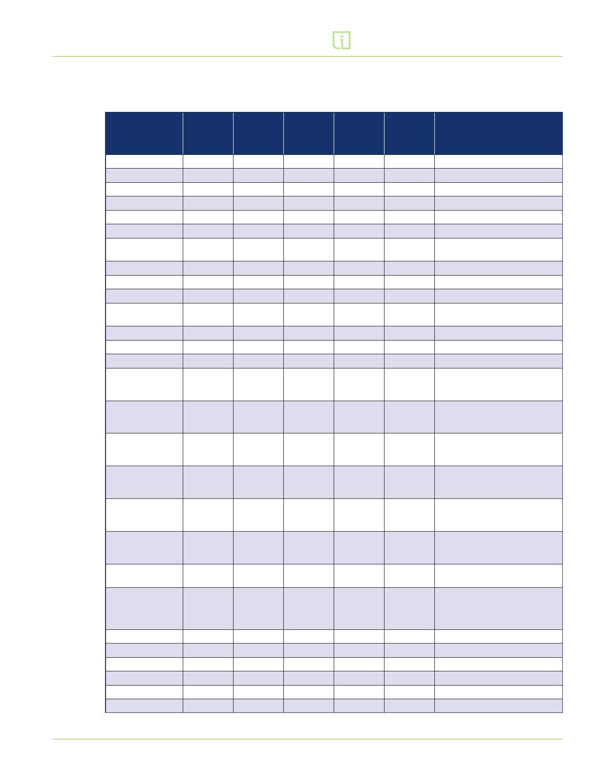
The following registers represent the sensor and alarm outputs available:
Name Register
Address
Modbus
Data
Address
[Dec]
Modbus
Data
Address
[Hex]
Number of
Modbus
Registers
Data
Type Description
Line 1 Voltage 30001 0 0 1 INT16 Line 1 RMS Voltage (V)
Line 2 Voltage 30002 1 1 1 INT16 Line 2 RMS Voltage (V)
Line 3 Voltage 30003 2 2 1 INT16 Line 3 RMS Voltage (V)
Load 1 Voltage 30004 3 3 1 INT16 Load 1 RMS Voltage (V)
Load 2 Voltage 30005 4 4 1 INT16 Load 2 RMS Voltage (V)
Load 3 Voltage 30006 5 5 1 INT16 Load 3 RMS Voltage (V)
Ground Status 30007 6 6 1 UINT16 1: GND/Earth Present,
0: GND/Earth Fault
Switch Status 30008 7 7 1 UINT16 1: Switch Open, 0: Switch Closed
Temperature 30009 8 8 1 INT16 Temperature (°C); Multiply by 0.1
Humidity 30010 9 9 1 UINT16 Relative Humidity (%); 0-100
Liquid
Accumulation 30011 10 A 1 UINT16 1: Liquid Accumulation Detected,
0: Absence of Liquid
Line 1 Avg Voltage 30012 11 B 1 INT16 Not yet implemented
Line 2 Avg Voltage 30013 12 C 1 INT16 Not yet implemented
Line 3 Avg Voltage 30014 13 D 1 INT16 Not yet implemented
Line 1 LED 30015 14 E 1 UINT16
Line 1 Voltage State 0: O
(Normal), 2: Energized (Normal),
4: Improper Voltage
Line 2 LED 30016 15 F 1 UINT16
Line 2 Voltage State 0: O
(Normal), 2: Energized (Normal),
4: Improper Voltage
Line 3 LED 30017 16 10 1 UINT16
Line 3 Voltage State 0: O
(Normal), 2: Energized (Normal),
4: Improper Voltage
Load 1 LED 30018 17 11 1 UINT16
Load 1 Voltage State 0: O
(Normal), 2: Energized (Normal),
4: Improper Voltage
Load 2 LED 30019 18 12 1 UINT16
Load 2 Voltage State 0: O
(Normal), 2: Energized (Normal),
4: Improper Voltage
Load 3 LED 30020 19 13 1 UINT16
Load 3 Voltage State 0: O
(Normal), 2: Energized (Normal),
4: Improper Voltage
GND LED 30021 20 14 1 UINT16 Ground Continuity State
2: Normal, 4: Fault
Fault LED 30022 21 15 1 UINT16
General warning error states
2: Normal, 6: Fault. Includes liquid
accumulation sensor and
internal communication state
Load 1 Current 30023 22 16 2 INT32 Load 1 current in mA
Load 2 Current 30025 24 18 2 INT32 Load 2 current in mA
Load 3 Current 30027 26 1A 2 INT32 Load 3 current in mA
Load 1 Avg Current 30029 28 1C 2 INT32 Not yet implemented
Load 2 Avg Current 30031 30 1E 2 INT32 Not yet implemented
Load 3 Avg Current 30033 32 20 2 INT32 Not yet implemented
leviton.com/inform6
Inform Modbus Setup Guide
2.5. DEVICE INFORMATION REGISTERS
The following registers represent the device information available:
Name Register
Address
Modbus
Data
Address
[Dec]
Modbus
Data
Address
[Hex]
Number of
Modbus
Registers
Data
Type Description
Wiring Config 31001 1000 3E8 6 String*
3-7 characters,
plus null terminator:
1P+N+E = Single Phase, Neutral,
Ground
2P+E = Single (split) Phase,
Ground
2P+N+E = Single (split) Phase,
Neutral, Ground
3P+E = Three-phase, Ground
3P+N+E = Three-phase, Neutral,
Ground
3PB+E = 4-wire Delta B leg high
3PB+N+E = 5-wire Delta B leg
high
3PB+E = 4-wire Delta B leg high
3PB+N+E = 5-wire Delta B leg
high
3PC+E = 4-wire Delta C leg high
3PC+N+E = 5-wire Delta leg
high C
3PC+E = 4-wire Delta C leg high
3PC+N+E = 5-wire Delta C leg
high
Voltage Config 31007 1006 3EE 2 uint16 DIP switch-based
user-configured nominal voltage
Reserved 31013-
31100 87
Model Number 31101 1100 44C 32 String* Device model number; 1-63
characters, plus null terminator
Serial Number 31133 1132 46C 16 String* Device serial number; 1-31
characters, plus null terminator
Display PCBA FW
Version 31149 1148 47C 6 String*
Display PCBA firmware version;
5-11 characters plus null
terminator
Power Sense PCBA
FW Version 31155 1154 482 6 String* Power Sense PCBA firmware
version number; 5-11 characters
Modbus PCBA FW
Version 31161 1160 488 6 String* Modbus board firmware version
number; 5-11 characters
*String data stored in hex bytes
leviton.com/inform 7
Inform Modbus Setup Guide
2.6. SENSOR DATA FORMAT
Sensor data as delivered as signed and unsigned integers and strings. Consequently, numeric
conversion may be required to display in preferred conventional units.
2.6.1. Voltage Format
The voltage value displayed for Line 1, Line 2, Line 3, Load 1, Load 2, and Load 3 is the measured
RMS phase voltage measured at their respective switch terminals. Line 1 Avg, Line 2 Avg, and
Line 3 Avg are calculated values. Volts (V) = ModbusData.
2.6.2. Current Format
The current value displayed for Line 1 Current, Line 2 Current, and Line 3 Current is the measured
RMS current in milliamps. Line 1 Avg Current, Line 2 Avg Current, and Line 2 Avg Current are
calculated values. Amps (A) = (ModbusData) /1000
2.6.3. Temperature Format
The measured temperature range is -40.0°C to 125.0°C.
The Modbus data range is -400 to 1250. Temperature (°C) = (ModbusData) /10.
2.6.4. Humidity Format
The measured relative humidity range is 0% to 100%. The Modbus data range is 0 to 100.
Relative Humidity (%) = ModbusData.
2.6.5. Ground Continuity
The ground continuity sensor has a two-state output: present or fault.
The Modbus data is 0 (fault) or 1 (present).
2.6.6. Liquid Accumulation
The liquid accumulation sensor has a two-state output: liquid absent or present.
The Modbus data is 0 (absent) or 1 (present).
2.6.7. Switch Position
The switch position sensor has a two-state output: switch open or closed.
The Modbus data is 0 (closed) or 1 (open).
leviton.com/inform8
Inform Modbus Setup Guide
2.7. ERROR DETECTION
The Inform technology firmware processes the sensor outputs to determine if they are normal
for the specified operating conditions. There are a series of status registers that can be used for
alerting abnormal operating conditions. These registers control the LED display on the device and
are also available to external devices.
2.7.1. Voltage alarms
The voltage sensor outputs, switch position indicator output, and device configuration settings
are analyzed to determine if the voltage level present on each switch terminal is normal.
These registers are Line 1 LED, Line 2 LED, Line 3 LED, Load 1 LED, Load 2 LED, and Load 3 LED.
Unused terminals yield a “normal – OFF” output.
Load side terminals that are de-energized with the switch turned to the o position
also yield an “OFF - normal” output.
An RMS voltage of ≤ 50 V is classified as “de-energized”.
Applicable line side terminals and corresponding load side terminals that are energized
when the switch handle is turned to the ON position yield an “Energized - normal” output.
Terminals with voltage present when there should not be, or improper voltage level, yield
an output of “improper voltage level.
The Modbus data is 0 (O - Normal), 2 (Energized - Normal), or 4 (Improper voltage level).
2.7.2. Ground Continuity Alarm
This alarm is a redundant register for indicating the ground continuity sensor’s status, either
normal or fault. The Modbus data is 2 (Normal) or 4 (Fault).
2.7.3. General Fault Alarm
This register is a “catch-all” for a variety of error conditions. If the device experiences any
internal communication failures between the sensor and processing electronics or the liquid
accumulation sensor detects liquid, an alarm will be generated. The Modbus data is 2 (normal)
or 6 (error detected).
2.7.4. Modbus Errors
Situation Error Response Modbus Error Code
Query is not an allowable action for the server (slave) Invalid Function Error 0x01
Writing to an undefined holding register Invalid Address Error 0x02
Writing invalid data to a holding register Invalid Data Error 0x03
Reading undefined holding register Invalid Address Error 0x02
Reading undefined input register Invalid Address Error 0x02
Incorrect CRC None N/A
Incorrect Parity None N/A
Incomplete Modbus Message None N/A
Incorrect interbyte timing None N/A
leviton.com/inform 9
Inform Modbus Setup Guide
3.1. INTRODUCTION
Leviton devices with Inform Technology incorporate firmware that provides critical functions,
including sensor element interface, sensor value processing, error detection, and Modbus operation.
The firmware includes a boot loader for in-field firmware updates via Leviton’s Inform Mobile App. It is
recommended that installer check for updated firmware after the initial installation and, if available,
perform the update as described in section 3.1.2.
Additionally, the Inform Mobile App provides a utility for setting the Modbus device ID and network
communication parameters
3.1.1. Required Equipment
Mobile device with Bluetooth enabled
Inform mobile app
3.1.2. Updating Firmware
NOTE: The firmware update process utilizes a Bluetooth-enabled mobile device and the Inform
Mobile App to transfer the firmware file to the Inform device. Therefore, you must be in close
proximity to the Inform device requiring the firmware update.
Step 1. Using the Inform mobile app, navigate to Modbus from the main menu.
Step 2. Select the Inform device you wish to update
If multiple Inform devices are in range, you can identify the correct Inform device
by tapping the magnifying glass icon to the left of the Inform device name.
This will flash the LEDs 10 times on the corresponding Inform device.
Tap on the arrow to the right of the Inform device name
Step 3. Tap the Update Available / Start Update button
The update process may take several minutes to complete
Step 4. Tap the Finish button
3. SOFTWARE
Leviton Manufacturing Co., Inc.
201 N Service Rd, Melville, NY 11747
Telephone: 1-800-323-8920 • FAX: 1-800-832-9538
© 2022 Leviton Manufacturing Co., Inc. All rights reserved. Specifications subject to change without notice. Q-1314B
CONTACT INFORMATION
User Support
Tech Line: 1-800-824-3005
Monday - Friday 8 AM - 10 PM ET
Saturday 9 AM - 7 PM ET
Sunday 9 AM - 5 PM ET
Website: leviton.com/inform
Inform Modbus Setup Guide
3.1.3. Setting Device ID and Network Communication
NOTE: This process utilizes a Bluetooth-enabled mobile device and the Inform Mobile App to
modify these settings of the Inform device. Therefore, you must be in close proximity to the
Inform device requiring these changes.
Step 1. Using the Inform mobile app, navigate to the Modbus section from the main menu.
Step 2. Select the Inform device you wish to modify
If multiple Inform devices are in range, you can identify the correct Inform device by
tapping the magnifying glass icon to the left of the Inform device name. This will
flash the LEDs 10 times on the corresponding Inform device.
Tap on the arrow to the right of the Inform device name
Step 3. Adjust the parameters as required to integrate with the target network.
To change device ID, enter a number between 1 and 247 that is unique to the
target network loop.
For network communication parameters, select the values from the drop down
menu that correspond with the target network loop.
NOTES:
110521
  • Page 1 1
  • Page 2 2
  • Page 3 3
  • Page 4 4
  • Page 5 5
  • Page 6 6
  • Page 7 7
  • Page 8 8
  • Page 9 9
  • Page 10 10

Leviton Inform User guide

Type
User guide

Sure, here is a brief product information for Leviton Inform:

Leviton Inform: The Leviton Inform is a versatile device that provides real-time monitoring and control of electrical parameters. With its advanced Modbus communication capabilities, it enables seamless integration with industrial automation systems, building management systems, and energy management platforms. It offers a wide range of features, including voltage monitoring, current monitoring, temperature monitoring, humidity monitoring, liquid accumulation detection, and switch status monitoring.

It supports various Modbus functions for flexible data exchange, including reading holding registers, reading input registers, and writing holding registers. The device's configuration registers allow for easy adjustment of communication parameters such as baud rate, parity, and stop bits.

Ask a question and I''ll find the answer in the document

Finding information in a document is now easier with AI