Page is loading ...

INSTALLATION AND OPERATING GUIDE
For
Electric Heaters
Marseilles
(Model 801)
&
SONNET
(Model 802)
600B602/01
This guide is intended to help you install and care for
your Wonderfire electric heater. Please read carefully
before installing and using your heater.
Important
Please keep your Guide in a safe place for future
reference

2
CUSTOMER CARE
Thank you for choosing Wonderfire
All Wonderfire heaters are designed to meet the most stringent quality, performance and safety requirements to provide
our customers with many years of trouble free service. This guide aims to improve your understanding and appreciation of
your new heater, by providing simple and informative instructions to enable you to install it and to ensure that you benefit
from the excellent performance and features it has to offer.
If you require further assistance, your dealer will be pleased to help.
FOR USEFUL TELEPHONE NUMBERS SEE THE BACK COVER
IMPORTANT SAFETY INSTRUCTIONS
It is important that the following safety instructions are followed
Always
Always install the heater in accordance with the instructions, if in doubt obtain expert
advice.
Always make sure the electrical socket is accessible and located adjacent to, but not above
the heater.
Always disconnect the heater from the electrical supply before carrying out cleaning,
maintenance or replacing lamps.
Always make sure the heater is firmly secured to the fireplace opening to prevent the fire
from being tipped over.
Always use a fireguard when young children and infirm persons can come into contact
with the heater.
Always use genuine Wonderfire spares.
Never
Never leave children unsupervised in a room where the heater in ON and unguarded.
Never obstruct or cover the fan outlet or force items into heater openings.
Never install or use the heater anywhere where water is in use, i.e. Bathrooms, Shower
Rooms etc.
Never use aerosols on or around the heater.
Never route the mains supply cable under carpet etc.
Never install the heater close to curtains or combustible materials.
Never use the heater to dry clothes etc.

3
General
This heater is intended for use in a fireplace opening generally conforming to British Standard 1251 for a nominal 400mm
(16 inch) or 450mm (18 inch) Fireplace. It may also be located in other fireplace openings or in a wooden surround,
where the following dimensions are available.
Width 390 – 450mm (15.3/8 – 17.3/4 inches)
Height 555 – 590mm (21 7/8 – 23.1/4 inches)
Depth At least 75mm (3 inches)
Spacers and Wall Kits:
The heater is of a slim design and should suit most fireplace openings and fire surrounds, however there may be some
applications that require the need for either a spacer or flat wall kit. The following table identifies which spacer or wall kit
is available for each heater. These optional kits are obtainable from the your Wonderfire dealer.
Model 60mm (2.1/2”) Surround Rebate Flat Wall (no recess)
20mm Spacer Kit No. 75mm Wall Kit No.
Marseilles model 801 05801S1 05801U1
Sonnet model 802 05801R1 05801T1
Unpacking
These heaters are packed in a single carton. This contains the main appliance. In a separate box within the carton is the
cast facia complete with coal pack.
Installation
The heater must be fixed into position to prevent it from being tipped over.
The following fixing options are available. The parts required for both fixing options are included with all appliances.
Screw fixing
Wire fixing
The heater must not be located under a fixed electrical socket, the socket must always be accessible in order to disconnect
the heater from the electrical supply for maintenance or when replacing a lamp.
Important! This heater must be earthed. The heater is supplied with a 3 pin 13A fused re-wireable plug with 1mm².
3 core mains cable,
L = Brown N = Blue E= Green/Yellow
The mains supply cable must be safely routed from the heater to an electrical socket. Provision is made for left/right or rear
cable entry. Using one of the three cable guides at the base of the heater. To relocate, open the appropriate latch on the
cable guide and refit the mains cable into the required position. If the mains cable is damaged, to avoid a hazard it must be
replaced by a qualified person.
The heater body should be fixed in position before the front surround is finally fitted.
N.B:Please study the illustrations carefully to avoid damage to the heater.

4
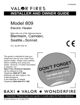
Figure 4
Figure 3
Figure 2
Figure 1
Figure 5
Front Removal
Marseilles model 801
Detach the control linkage – See figure 1
Marseilles and Sonnet models 801 & 802
Carefully remove the front surround by removing the two trim fixing screws and lifting
upwards and forward – See figure 2
Do Not Lift The Front Surround By The Control Knob
Keep the front surround and screws in a safe place when installing the fire.
Offer the heater body to the fireplace opening to ensure that it will fit before continuing with the
installation.
Appliance Fixing
Method A – Screw Fix
There are two slots in the top flange – See figure 3. Mark the fixing position through the slots.
Remove the heater. Drill a hole with a No.12 drill bit at each marked position. Insert the wall
plugs provided. Reposition the heater body and screw through the slots to provide a secure fixing.
Method B – Wire Fix
The fixing kit includes a steel wire and eyebolt to attach the heater to the back of the fireplace
opening.
Mark the position for the eyebolt at the back of the fireplace opening equal to the centre line of
the heater and at a height of 533 – 560mm. Drill, plug and screw in the eyebolt – See figure 4.
Thread one end of the steel wire through the two holes in the top flange, passing the wire
through the eyebolt and out through one of the opposite holes on the top flange – See figure 4.
Locate the heater into the fireplace opening, then by gently pulling the steel wire, gather up the
excess until the heater is firm.
Thread the wire back through the remaining hole to lock the wire and heater in place – See
figure 4.
Method C – With optional 20mm Wall Spacer
The spacer should be fixed to the fireplace opening or surround using the screws provided. The
heater must then be fixed to the spacer using the screws provided. (See kit instructions).
Method D – With optional 75mm Wall Spacer Kit
The wall kit should be securely fixed to the wall using the screws provided. The heater must
then be fixed to the wall kit (see kit instruction).
If fixing through marble, ensure that both rawlplug and screw pass freely through the marble.
Secondary Screw fixing
If felt beneficial, the appliance can be additionally secured by screws through the side flanges – see
figure 5.

5
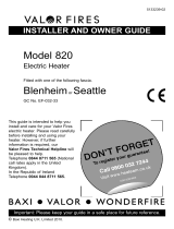
Figure 6
Figure 7
Figure 8
Figure 9
Assembly of Fronts
All Models
Carefully lift the front surround. Hook the front surround onto the retaining plates on
the heater body and lower the front surround down – See figure 6.
Marseilles model 801
Check that the switch control spindle is in the OFF position and the slider is in the
OFF position. Swing the control linkage/boss towards the control spindle on the
heater and push the boss onto the spindle, ensuring the “D” flats are in alignment –
See figure 7
Final Assembly
With the two screws provided, fix the front surround to the heater body – See figure 8
Check the controls to make sure they operate smoothly.
Place the front casting/fuel support in position by passing the screw heads through the key hole
slots in the surround and lowering down – See figure 9.
Fuel Effects
Open the polythene bag containing the loose coals and place them on and in front of the
coal support to give the most pleasing effect. It is not necessary to use all the coals
supplied.
Place the ash pan into position below the casting.
Operating the Heater
Never cover the heater, there is a risk of fire if covered.
Sonnet model 802
The heater is operated by three switches, located below the canopy.
Switch 1 = O Main On – Off
In the On position only the fuel effect light operates
Switch 2 =
❙ 1 kW fan heat setting and fuel effect
Switch 3 =
❙❙ 2 kW fan heat setting and fuel effect
The switches are mechanically interlocked, so when switch 1 is turned off, all switches turn off.
Marseilles model 801
These models have a slider control located on the right side of the surround for operating the main functions of the heater.
Located to the left of the fan outlet grille is a lamp dimmer control and a room thermostat control.
The Lamp Dimmer is used to set the light output of the fuel effect between off and high as required.
The Room Thermostat is used to maintain room temperature, the higher the setting, the higher the room temperature
will be before the heater turns off. When using the fan Coolblow setting, the thermostat should be turned to a high
position.
The Slider Control
There are four slider positions
n Off
Fuel effect lighting on
Fan Coolblow on. Fuel effect lighting on (Set thermostat at High).
Fan heater on (2kw). Fuel effect lighting on (Set thermostat to a high setting and
allow the room temperature to settle before re-adjusting).

6
Maintaining Your Fire
Always disconnect the heater from the electricity supply by removing the 3 pin plug and allowing
the heater to cool before undertaking maintenance or replacing lamps.
Lamp Replacement
The lamps fitted to this heater are long life types, but due to the indeterminate life span and ease of replacement are
specifically excluded from the guarantee.
To replace a lamp.
Remove the accessible loose coals. Unhook the front by lifting slightly to disengage the unit from the keyhole slots in
the trim and gently pull forward – See figure 6.
Replace with a 60W (maximum) clear Edison screw type lamp. Do not use opaque or coloured lamp bulbs.
Refit the front castings and relocate the coals.
Automatic Cut Out
A cut out is fitted to the heating element to prevent damage due to over heating. If it operates due to an obstruction in the
airflow, the heater must be turned off and allowed to cool for 15 minutes, obstruction removed before restarting.
Care and Cleaning
The canopy trims and glass parts need only to be wiped clean with a dry soft cloth, do not use polishes or abrasive
materials.
Fault Finding
No or low light from the fuel effect: Check the lamp dimmer is turned to high, if it is, then it is possibly a lamp failure.
Remove the lamp as detailed above and check it in a table lamp, that is known to work.
No heat or light: Check the wall socket by plugging in a known working appliance. If functional check the 13A fuse in
the heater plug. If either fuse or socket is suspected, have them checked by an electrician.
Light but no heat: The automatic cut out, may have operated, see above.
Disposal
At the end of the products serviceable life it should be disposed of thoughtfully and safely in accordance with local
authority regulations. The plug should be removed from the mains cable and the mains cable cut from the heater.

7
USEFUL TELEPHONE NUMBERS
• Your Post Code
• Type of Fire
• Model / Name
• Serial Number
• The fault, problem or request
To report faults or arrange for your Wonderfire heater to be serviced
VALOR SERVICE 0121 386 6203
To order spares or for sales information
Contact your Wonderfire dealer
Callers in the Republic of Ireland
Call 353 183 75114
To help us quickly help you, please try to have
the following information available before
y
ou contact us.
/