Wonderfire 850 Installer And Owner Manual
- Category
- Fireplaces
- Type
- Installer And Owner Manual
Wonderfire 850 is an electric heater equipped with a Bauhaus fascia. It comes with a 3 pin 13 Amp fused plug with 1mm² 3 core cable. The wires in the cable are coloured in accordance with the following code:
- Live = Brown
- Neutral = Blue
- Earth = Green/Yellow It can be installed in different ways and places, depending on your needs. It can be fitted into a 'hole in the wall', a surround or fireplace opening, or against a flat wall with the base of the heater on a hearth or similar surface. It also can be fitted below a shelf, mantle, or similar.

© Baxi Heating U.K. Limited 2010.
5136405/02
Model 850
ELECTRIC HEATER
Fitted with a
Bauhaus fascia.
(GC No. EF-032-41)
Important: Please keep your guide in a safe place for future reference.
INSTALLER AND OWNER GUIDE
This guide is intended to help you
install and care for your Wonderfire
Premier electric heater. Please read
carefully before installing and using
your heater. However, if further
information is required, our
Wonderfire Premier Technical
Helpline will be pleased to help.
Telephone 0844 8711 554 (National
call rates apply in the United
Kingdom).
In the Republic of Ireland
Telephone 0044 844 8711 554.

© Baxi Heating U.K. Limited 2010.
All rights reserved. No part of this publication may be reproduced in any material form
(including photocopying), stored in any medium by electronic means (including in any
retrieval system or database) or transmitted, in any form or by any means, whether
electronic, mechanical, recording or otherwise, without the prior written permission of
the copyright owner.
Applications for the copyright owner's permission to reproduce any part of this
publication should be made, giving details of the proposed use, to the following
address: The Company Secretary, Baxi Heating UK Limited, The Wyvern Business
Park, Stanier Way, Derby, DE21 6BF.
Warning: Any person who does any unauthorised act in relation to a copyright work
may be liable to criminal prosecution and civil claims for damages.
Wonderfire Premier, Wood Lane, Erdington, Birmingham B24 9QP
www.wonderfire.co.uk
Because our policy is one of constant development and improvement, details may vary slightly from
those given in this publication
INSTALLER AND OWNER GUIDE
Page 2
© Baxi Heating U.K. Limited 2010.

Safety First.
Wonderfire Premier heaters are CE Approved and designed to meet the appropriate
British Standards and Safety Marks.
Quality and Excellence.
All Wonderfire Premier heaters are manufactured to the highest standards of quality
and excellence and are manufactured under a BS EN ISO 9001 quality system
accepted by the British Standards Institute.
CUSTOMER CARE
Thank you for choosing Wonderfire Premier
All Wonderfire Premier heaters are designed to meet the most stringent quality,
performance and safety requirements to provide our customers with many years of
trouble free service. This guide aims to improve your understanding and appreciation
of your new Wonderfire Premier heater, by providing simple and informative
instructions to enable you to install it and to ensure that you benefit from the excellent
performance and features it has to offer.
If you require further assistance, the Wonderfire Premier Technical Helpline will
be pleased to help.
Please telephone 0844 8711 554 (local rates apply in the United Kingdom). In the
Republic of Ireland please telephone 0044 844 8711 554.
INSTALLER AND OWNER GUIDE
Page 3
© Baxi Heating U.K. Limited 2010.

1. HANDLING AND UNPACKING
Before continuing any further with the installation of this heater please read the
following:
Important instructions.
The approximate lifting weight (kg) of the heater parts are listed below:
Model Heat engine Fascia Spacer
Bauhaus 7.14 6.21 1.0*
An optional spacer frame kit is obtainable either from your heater supplier or direct
from Wonderfire Premier Sales. The kit is an 75mm deep spacer kit (Kit number
05801T1). This spacer enables the heater to be flat wall fixed.
One person should be sufficient to lift the heater. If for any reason this weight is
considered too heavy then obtain assistance.
When lifting always keep your back straight. Bend your legs and not your back.
Avoid twisting at the waist. It is better to reposition your feet.
Avoid upper body / top heavy bending. Always bend from the knees rather than
the waist. Do not lean forward or sideways whilst handling the heater.
Always grip with the palm of the hand. Do not use the tips of fingers for support.
Always keep the heater as close to the body as possible. This will minimise the
cantilever action.
Use gloves to provide additional grip.
Always use assistance if required.
2. SAFETY
This appliance is not intended for use by persons (including children) with reduced
physical, sensory or mental capabilities, or lack of experience and knowledge, unless
they have been given supervision or instruction concerning use of the appliance by a
person responsible for their safety.
Children should be supervised to ensure that they do not play with the appliance.
Always
Always install the heater in accordance with this guide. If in doubt obtain
expert advice.
Always make sure the electrical socket is accessible and located adjacent to,
but not above or behind the heater.
Always disconnect the heater from the electrical supply before carrying out
cleaning or maintenance.
INSTALLER AND OWNER GUIDE
Page 4
© Baxi Heating U.K. Limited 2010.

Always ensure that the electrical supply is OFF before removing the mains cable
from the rear of the heater.
Always use a fireguard when young children and infirm persons can come into
contact with the heater.
Always use genuine Wonderfire Premier spares.
Never
Never leave children unsupervised in a room where the heater is ON and
unguarded.
Never use the heater in a small room when occupied by persons not able to
leave the room by themselves unless constantly supervised.
Never obstruct or cover the fan outlet or force items into heater openings.
Never install or use the heater anywhere where water is in use, i.e.
Bathrooms, Kitchens, Shower Rooms and Swimming Pools etc.
Never use aerosols or steam cleaners on or around the heater.
Never route the electric cable under carpet etc.
Never install the heater close to curtains or combustible materials.
Never use the heater to dry clothes etc.
Never sit or stand on the heater.
Never use the heater with a timer switch or similar device.
Important Electrical Safety.
The heater must not be located in front of or under an electrical socket; the socket
must always be accessible in order to disconnect the heater from the electrical supply
for maintenance and cleaning.
CAUTION: In order to avoid a hazard due to inadvertent resetting of the thermal cut out,
this appliance must not be supplied through an external switching device, such as a
timer, or connected to a circuit that is regularly switched on and off by the utility.
Important! This heater must be earthed.
The heater is supplied with a 3 pin 13 Amp fused plug with 1mm² 3 core cable.
The wires in the cable are coloured in accordance with the following code:-
Live = Brown
Neutral = Blue
Earth = Green /Yellow
The electric supply must be safely routed from the heater to an electrical socket.
If the electric cable is damaged, to avoid a hazard it must be replaced by a
Wonderfire Premier authorised service agent, or similarly qualified person (See page
20 for contact numbers). All external wiring between the heater and the electrical
supply shall comply with current IEE regulations. Extension leads should not be used.
INSTALLER AND OWNER GUIDE
Page 5
© Baxi Heating U.K. Limited 2010.

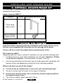
3. OPTIONAL SPACER FRAME KIT
The following kit is obtainable either from your heater supplier or direct from
Wonderfire Premier Sales.
Spacer frame kit 05801T1.
4. FITTING THE HEATER
Important: Before continuing with the installation of this heater please ensure
that you have completed the information on the last page of this guide.
Please read this section thoroughly before positioning the heater.
Do I need any tools?
Depending upon the chosen method of installation you may need the following tools: -
For Spacer frame or screw fixed installations you will need a Pozidrive / Phillips
/ cross head screwdriver. This should have a number 2 size tip.
If wire fixing and drilling into brickwork you will need a power drill (preferably with
hammer action) and appropriate size drill bit for the wall plugs supplied.
Where and how can you fit the heater?
Q Can the heater be installed into a ‘hole in the wall’ (elevated opening)?
A We do not recommend the heater for this type of installation.
Q Do you want to fit the heater into a surround or fireplace opening without
the optional spacer frame?
A The minimum rebate / depth required is 70mm.
INSTALLER AND OWNER GUIDE
Page 6
© Baxi Heating U.K. Limited 2010.
Figure 1.
Contents Quantity (Illustrations are not to scale)
75mm deep
Spacer frame
1
No 8 x 3/8 Self-
tapping screws
4

Q What opening size do you need in the surround or fireplace opening?
A This heater can be fitted into fireplaces or surrounds where the following
dimensions are available.
Width 395mm - 450 mm
Height 555mm - 590 mm
Depth At least 70mm
Q Do you want to fit the heater against a flat wall with the base of the heater
on a hearth or similar surface?
A You will need to purchase the optional spacer frame kit (kit number 05801T1).
This spacer enables the heater to be flat wall fixed. The depth of the spacer
frame is 75mm.
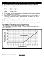
Q Do you want to fit the heater below a shelf, mantle or similar?
A You will have to allow the clearances as shown below:
The minimum height from the base of the heater to the underside of any shelf made
from wood or other combustible materials is detailed below.
• For a shelf up to 150mm deep: Minimum height = 700mm.
• For a shelf deeper than 150mm: 700mm + 12.5mm for every 25mm depth over
150mm (See Figure 2).
INSTALLER AND OWNER GUIDE
Page 7
© Baxi Heating U.K. Limited 2010.
Figure 2. Combustible shelf clearances

General notes to read before fitting your heater.
If fitting the heater onto a reflective or shiny surface such as a hearth we
recommend that this surface does not extend further than 300mm from the fixing
plane (wall). Reflective or shiny surfaces that project further than 300mm may
reflect an image of the internal light source.
When the fuel effect is on, it will be possible to see reflected light and movement
behind the outlet louvre at the top of the heater.
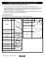
Securing the heater.
The contents have been identified in figure 3 (Fascia not shown).
Contents Qty. (Not to scale)
Heater 1
Securing clamp 1
M5 x 40mm
Securing clamp
screw
1
No.8 x 3/8
pan head screw
5
Tension wire 1
Screweye 1
Wood screw 5
Wall plug 5
Figure 3. Contents
INSTALLER AND OWNER GUIDE
Page 8
© Baxi Heating U.K. Limited 2010.
Contents Qty. (Not to scale)
‘AAA’ Battery 2
Handset 1
Mains cable 1
Infill trim 1

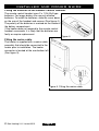
Fitting the batteries to the Remote Control Handset.
The remote control handset uses 2 x 1.5V AAA type
batteries. For longer battery life use only alkaline
batteries. To install the batteries, slide the cover down
on the rear of the handset and remove (See figure 4).
The polarity of the batteries is marked on the inside of
the battery compartment.
If the heater does not respond to the remote control
handset commands, it is likely that the batteries are
faulty or require replacement.
Fitting the mains cable.
The heater is supplied with a mains cable
assembly that should be connected to the
heater prior to installation. The heater
connector is located at the rear bottom left
(See figure 5).
INSTALLER AND OWNER GUIDE
Page 9
© Baxi Heating U.K. Limited 2010.
Figure 5. Fitting the mains cable
Figure 4.

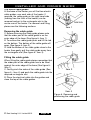
The mains cable guides.
At the base of the heater you will find two electric
cable guides, one each side of the heater. If
required, the cable guide on the right hand side
(looking from the front of the heater) can be
removed and put in the rectangular slot in the
centre rear of the heater. For removal and fitting
please see the following sections.
Removing the cable guide.
1. Before removing the cable guide please note
that the wider part of the cable guide is on the
outer edge of the base (See figure 6- Item 1).
2. To remove the cable guide push and lift the tab
on the bottom. The bottom of the cable guide will
open (See figure 6- Item 2).
3. Hold the bottom of the cable guide close to the
heater then gently pull the cable guide away from
the rectangular slot (See figure 6- Item 3).
Fitting the cable guide.
When fitting the cable guide please remember that
the wider part of the cable guide has to be fitted
against the outer edge of the base (See figure 6-
Item 1).
1. Gently pinch the sides of the cable guide (See
figure 6 - Item 4) and push the cable guide into the
required rectangular slot.
2. Place the electrical cable into the guides and
close the top of the cable guides.
INSTALLER AND OWNER GUIDE
Page 10
© Baxi Heating U.K. Limited 2010.
Figure 6. Removing and
positioning the cable guide.
Item 1
Item 2
Item 3
Item 4

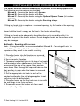
The heater must be secured into position to prevent it from being tipped over.
The following securing options are available:
Method A - Securing the heater with Screws.
Method B - Securing the heater with Wire.
Method C - Securing the heater using the Optional Spacer Frame (kit number
05801T1).
Method D - Securing the heater using the Securing clamp.
If fitting the heater into a fireplace or surround opening, try the heater in the opening
to ensure that it will fit.
Never hold the hood / canopy on the front of the heater when lifting.
If fitting the heater onto a decorative hearth surface such as marble or tile it is
advisable to protect the hearth surface. Do not drag the heater as the surface finish
may be damaged.
Method A - Securing with screws.
Note - If fixing to marble it is recommended that Method B - ‘Securing with wire’ is
used. Drilling marble without the correct tools and
experience may result in the marble cracking.
1. Place the heater into the fireplace or surround
opening. Make sure that the heater is in the middle
of the surround or fireplace.
2. There are two slotted holes in the top of the heater
and four holes in the side flanges (See figure 7). We
recommend the use of two upper holes and two
lower holes. Mark through the required holes so that
their position is clear when the heater is removed.
3. Remove the heater.
4. Drill an appropriate size hole in each of the
marked positions for the wall plugs supplied. Insert
wall plugs into the drilled holes.
5. Place the heater so that the holes are in line with
the wall plugs in the fixing surface.
6. Screw and secure the heater with four wood
screws (See figure 3).
Figure 7. Screw location
INSTALLER AND OWNER GUIDE
Page 11
© Baxi Heating U.K. Limited 2010.

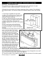
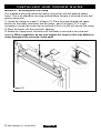
Method B - Securing with wire.
This method of securing is recommended where the wall / brickwork is in poor
condition or where marble back panels / surrounds are used.
Although this section deals with fireplace openings without a spacer, this method of
securing the heater it can also be used with the optional spacer frame (See method
C).
1. The fixing kit supplied with the heater
includes a wire and eyescrew. These can be
used to secure the heater to the back of a
surround / fireplace opening.
2. Mark the eyescrew position on the centre
line at the back of the fireplace opening and at
a height of 565-575mm (See figure 8).
3. Drill an appropriate size hole in the marked
position.
4. Insert a wall plug into the drilled hole.
5. Screw the eyescrew into the wall plug.
6. Position the heater in front of the fireplace
opening.
7. At the top of the heater there are four small
holes, two each side of the heater.
From the front of the heater, thread
about 50mm of the wire into the
outside small hole on the right side
of the heater (See point 1 - figure 9).
8. Thread the other end of the wire
through the remaining small hole to
the left. Continue to push the wire
through this hole until there is only a
small loop of wire at the front of the
heater (See point 2 - figure 9).
9. At the back of the heater there will
be a long piece and a short piece of
wire coming through the two holes.
Hold the short piece and give the
long piece a gentle tug. This will
secure the wire. Take the long piece and thread this through the eyescrew in the back
of the fireplace opening (See figure 9).
10. From the back of the heater thread the long piece of wire through the inner small
hole on the left hand side of the heater (See figure 9).
11. Locate the heater in the fireplace opening, then from the front of the heater, gently
INSTALLER AND OWNER GUIDE
Page 12
© Baxi Heating U.K. Limited 2010.
Figure 9. Wire fix
Figure 8. Eyescrew location

pull the wire on the right hand side to gather up the excess until the heater is secure.
Thread the wire through the remaining small hole to lock the wire and heater in place
(See point 4 - figure 9).
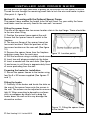
Method C - Securing with the Optional Spacer Frame.
The spacer frame enables the heater to be flat wall fixed. For your safety the frame
and heater must be securely fixed to the rear wall / surround.
Fitting the spacer frame
The rear of the spacer has two screw location slots in the top flange. These should be
to the rear when fitting.
1. Position the spacer frame against the wall.
Ensure that the spacer frame is central to the
fireplace.
2. The top rear flange of the spacer frame has
two screw locations. Mark the positions of the
two screw locations on the rear wall (See figure
10).
3. Remove the spacer frame from the fireplace
and place away from the work area.
4. Drill the locations using a suitably sized masonry drill bit for the wall plugs supplied.
5. Insert two wall plugs provided into the holes.
6. Insert a woodscrew into each hole (See figure
3) and screw in until there is approximately 6mm
of screw protruding from the wall.
Preparing the heater for installation.
1. Secure the spacer frames to the heater using
four No.8 x 3/8 screws supplied (See figures 11
and 1).
Fitting the heater.
1. Carefully lift the heater and locate the slots on
the rear of the spacer frame onto the screws in
the wall. The screws can be adjusted to ensure a
tight fit. When mounting to decorative surfaces
such as wallpaper be careful not to drag the
heater down the wall as this may damage the
decorative surface.
Figure 11. Fitting the spacer frame
to the heater
INSTALLER AND OWNER GUIDE
Page 13
© Baxi Heating U.K. Limited 2010.
Figure 10. Location points

Method D - Securing with the clamp.
This method of securing cannot be used in conjunction with the optional spacer
frame. This is an alternative securing method where fixing to a surround or rear wall
proves impractical.
1. Locate the clamp as in point 1 of figure 12. Place the screw through the upper
bracket on the heater and locate into the clamp - point 2 of figure 12. It is only
necessary to locate the screw, do not continue to turn it as this will elevate the clamp.
2. Place the heater into the surround / opening.
3. Rotate the clamp screw clockwise until the heater is secured in the surround /
opening. Where applicable, do not over-tighten the screw as this may deform or
cause damage to the surround / back panel.
INSTALLER AND OWNER GUIDE
Page 14
© Baxi Heating U.K. Limited 2010.
Figure 12.

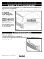
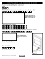
5. LIGHT SHUTTER ADJUSTMENT
The light shutter is an adjustable plate that increases and decreases the appearance
of the flames in the flame effect.
1. Switch on the fuel effect. If you are satisfied with the appearance of the flame effect
there is no need to adjust
the light shutter.
2. To adjust the light
shutter, loosen the two
screws then lift the shutter
to increase the
appearance of the flames
or lower it to decrease the
appearance of the flames.
3. When you have
obtained the required
flame appearance, tighten
the two screws and secure
the shutter in place.
6. FITTING THE FASCIA
Fitting the infill trim.
1. Remove the infill trim from its packaging.
2. Locate the four tabs on the rear of the infill trim into the four slotted holes in the
heater (See figure 14).
INSTALLER AND OWNER GUIDE
Page 15
© Baxi Heating U.K. Limited 2010.
Figure 14.
Figure 13.

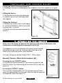
Fitting the fascia securing magnets.
1. Supplied in the fascia packaging are four magnets. Place the magnets as in figure
15.
Fitting the fascia.
1. Remove the fascia from its packaging.
2. Hold the fascia firmly and locate onto
the magnets.
Fitting the firefront.
1. Remove the firefront from its packaging.
2. Locate the firefront in front of the heater
ensuring that it is central.
3. Position the ash pan cover beneath the
firefront.
7. OPERATING THE HEATER
Never cover the heater or obstruct the opening at the base of the heater, this
could cause overheating and consequent risk of fire.
The appliance can be controlled by the manual control located
behind the ash pan cover on the lower right hand side of the
heater or by using the remote control handset.
The heat settings are quoted using a 240V ~ 50Hz supply.
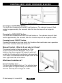
Remote Control - What do the buttons do?
Pressing the red ‘ON/OFF’ button.
To activate the remote handset it is necessary to press the red
ON/OFF button. The status lamp on the heater will turn red (see
figure 17).
Pressing the ‘EFFECT’ button.
This turns the Visualise effect on. The indicator lamp will flash
green for approximately five seconds, after this time the lamp will
no longer be visible (see figure 17).
INSTALLER AND OWNER GUIDE
Page 16
© Baxi Heating U.K. Limited 2010.
Figure 16.
Figure 15.

Pressing the ‘LOW HEAT’ button.
This turns the Visualise effect and 675 watt heater on. The indicator lamp will flash
amber for approximately five seconds, after this time the lamp will no longer be
visible.
Pressing the ‘HIGH HEAT’ button.
This turns the Visualise effect and 1350 watt heater on. The indicator lamp will flash
red for approximately five seconds, after this time the lamp will no longer be visible.
Pressing the red ‘ON/OFF’ button.
Pressing this button at any time whilst the Visualise effect and heater are in operation
will turn the Visualise effect and heater off.
Manual Control - What is it and why is it there?
The manual control is there as a back up. If the
remote control has been damaged, lost, or the
batteries lives have expired, the manual control will
enable the Visualise effect and heater to be operated.
The control is located behind the ash pan cover on the
lower right hand side of the heater.
What does the button do?
Press the button once.
This turns the Visualise effect on. The indicator lamp
will flash green for approximately five seconds, after
this time the lamp will no longer be visible.
INSTALLER AND OWNER GUIDE
Page 17
© Baxi Heating U.K. Limited 2010.
Figure 17. lamp locations
Figure 18.

Press the button a second time.
This will turn the 675 watt heater on. The Visualise effect will already be on. The
indicator lamp will flash amber for approximately five seconds, after this time the lamp
will no longer be visible.
Press the button a third time.
This will turn the 1350 watt heater on. The Visualise effect will already be on. The
indicator lamp will flash red for approximately five seconds, after this time the lamp
will no longer be visible.
Press the button a fourth time.
Pressing this button at any time whilst the Visualise effect or heater are in operation
will turn the Visualise effect and heater off.
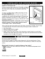
8. CLEANING AND MAINTAINING THE HEATER
Important Safety.
Before undertaking maintenance always disconnect the heater from the electricity
supply by removing the 3 pin plug and allowing the heater to cool.
How do I Clean my heater?
The heater and plastic parts need only to be wiped clean with a dry soft cloth; do not
use polishes or abrasive materials. This is especially important when cleaning the
effects screen.
I have a problem with my heater!
1. My remote control does not work.
The batteries in the remote control handset probably need replacing - See section 4
and figure 4. The heater can be operated manually as on page 17.
2. My heater is switched on but there is no effect or heat.
The first thing to do is check the wall socket. To do this plug in a known working
appliance. If the appliance you have plugged in works then there is a good chance
that the problem lies with the 13 Amp fuse in the heater plug. If either fuse or socket
is suspected, have them checked by an electrician.
3. My heater is on, I have selected a heat setting but there is no heat, just the
effect.
A cut out device is fitted to the heater to prevent damage due to over heating. If it
operates due to an obstruction in the airflow, the heater must be turned off and
allowed to cool for 15 minutes and the obstruction removed before restarting.
INSTALLER AND OWNER GUIDE
Page 18
© Baxi Heating U.K. Limited 2010.

4. I have dark areas in the fuel effect of my heater or the fuel effect is not as
bright as it was when new.
There is a mirror fitted to the rear of the hood / canopy at
the front of the heater and this may need cleaning. Wipe
the mirror with a clean, dry, non abrasive cloth (See
figure 19).
5. I have a problem that is different to those in the
previous examples 1- 4.
For general advice about your heater, to report faults,
arrange for your heater to be serviced, or for sales and
product information call 0844 8711 554. Callers in the
Republic of Ireland please telephone 0044 844 8711 554.
For spares inquiries
Spare parts are available nationwide via the ‘interpart
stockist network’. For your local stockist consult
Yellow pages under ‘Central Heating’.
When ordering spare parts please have the below information available. This will help
us to deal with your call quicker and avoid you having to make a second call.
Your Post Code.
Type of Heater (Electric or gas).
The fault, problem or request.
Model, Name and serial number (This information can be found on a small label
attached to the lower right of the heater (See figure 20) and should also have been
recorded on the last page of this guide.
9. ENVIRONMENT
Environmental Protection.
Waste electrical products should not be disposed of with household waste. Please
recycle where facilities exist. Check with your local authority or retailer for recycling
advice.
What should I do when I’m ready to dispose of my heater?
Remove the mains cable from the heater. This should be disposed of with
the heater.
INSTALLER AND OWNER GUIDE
Page 19
© Baxi Heating U.K. Limited 2010.
Figure 19.

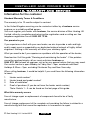
10. WARRANTY AND SERVICE
Information for the customer
Standard Warranty Terms & Conditions
The warranty is for 12 months subject to contract.
In the United Kingdom servicing can be carried out either by a heateam service
engineer or a suitably qualified person.
You must register your heater with heateam, the service division of Baxi Heating UK
Limited, either by completing and returning the registration card or calling our free
telephone registration line on 0800 032 72 44.
Our promise to you
If you experience a fault with your new heater, we aim to provide a safe and high
quality repair service supported by our dedicated national network of highly skilled
engineers. Nothing in this warranty will affect your statutory rights.
What you need to do if you experience a problem with the operation of the heater;
Read section 8 of this guide “Cleaning and maintaining the heater”. If the problem
cannot be resolved simply call our service division heateam on
0844 8711 554 to book an engineer visit or for any general advice that you may need.
Our contact centre is open Monday to Friday 8am – 6pm, weekends and Bank
Holidays 8.30am – 2pm, excluding Christmas Day and New Years day.
When calling heateam, it would be helpful if you could have the following information
to hand:-
1. Heater serial number*
2. Heater brand and model number*
3. Date of installation*
4. Proof of purchase (If you do not have the heater serial number)
*Note: Details 1 – 3 can be found on the last page of this guide.
What this warranty covers
Free of charge repair or replacement of components found to be of faulty
manufacture.
Free of charge replacement of the complete unit providing the failure is related to a
manufacturing fault that cannot be repaired or is uneconomic to repair.
Page 20
INSTALLER AND OWNER GUIDE
© Baxi Heating U.K. Limited 2010.
Page is loading ...
Page is loading ...
Page is loading ...
Page is loading ...
-
 1
1
-
 2
2
-
 3
3
-
 4
4
-
 5
5
-
 6
6
-
 7
7
-
 8
8
-
 9
9
-
 10
10
-
 11
11
-
 12
12
-
 13
13
-
 14
14
-
 15
15
-
 16
16
-
 17
17
-
 18
18
-
 19
19
-
 20
20
-
 21
21
-
 22
22
-
 23
23
-
 24
24


Wonderfire 850 Installer And Owner Manual
- Category
- Fireplaces
- Type
- Installer And Owner Manual
Wonderfire 850 is an electric heater equipped with a Bauhaus fascia. It comes with a 3 pin 13 Amp fused plug with 1mm² 3 core cable. The wires in the cable are coloured in accordance with the following code:
- Live = Brown
- Neutral = Blue
- Earth = Green/Yellow It can be installed in different ways and places, depending on your needs. It can be fitted into a 'hole in the wall', a surround or fireplace opening, or against a flat wall with the base of the heater on a hearth or similar surface. It also can be fitted below a shelf, mantle, or similar.
Ask a question and I''ll find the answer in the document
Finding information in a document is now easier with AI
Related papers
-
Wonderfire Gasflame 3 Owner's manual
-
-
-
-
-
-
Wonderfire AF 16 NV Installer And Owner Manual
-
-
-
Other documents
-
 Valor Fires 850 Installer And Owner Manual
-
 Valor Fires 845 Installer And Owner Manual
-
 Valor Fires Wellington Surround Installation guide
-
Valor Fires Carlton Installation guide
-
 Valor Fires 823 Installer And Owner Manual
-
 Valor Fires 809 Installer And Owner Manual
-
 Valor Fires 820 Installer And Owner Manual
-
 Valor Fires 820 Longlite Installer And Owner Manual
-
 Valor Fires Clarissa Installation guide
-
Valor 850 Installer And Owner Manual


