Powerware BPIV Installation & Operation Manual
- Type
- Installation & Operation Manual

www.powerwar e.com
BPIV
INSTALLATION & OPERATION MANUAL
UPS
10–15 kVA/20–30 kVA

ii
Powerware BPIV (10 kV A--30 kVA) Installation and Operation
164201406 Rev. C 013004
------------------------------------------------------------------------
------------------------------------------------------------------------
----------------------------------
IMPORTANT SAFETY INSTRUCTIONS
Instructions Importantes Concernant La Sécurité
SAVE THESE INSTRUCTIONS
Conserver Ces Instructions
This manual contains important instructions for your Uninterruptible Power
Supply (UPS) system. You should follow these instructions during the
installation and maintenance of the UPS, options, accessories, and batteries.
Cette notice contient des instructions importantes
concernant la sécurité.
This equipment has been tested and found to comply with the limits for a Class A
digital device, pursuant to Part 15 of the FCC Rules. These limits are designed to
provide reasonable protection against harmful interference when the equipment is
operated in a commercial environment. This equipment generates, uses, and can
radiate radio frequency energy and, if not installed and used in accordance with
the instruction manual, may cause harmful interference to radio communications.
Operation of this equipment in a residential area is likely to cause harmful
interference in which case the user will be required to correct the interference at
their own expense.

iii
Powerware BPIV (10 kV A--30 kV A) Installation and Operation
164201406 Rev. C 013004
Table of Contents
Introduc ti on xiii...............................................
System Configurations xiv........................................
Using This Manual xv............................................
Conventions Used in This Manual xvi...............................
Safety Considerations xvii.........................................
For More Information xviii..........................................
Getting Help xviii..................................................
Section I Installation
1
Getting Starte d 1---1..........................................
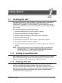
1.1 Installing the UPS 1---1......................................
1.1.1 Creating an Installation Plan 1---1.............................
1.1.2 Preparing Your Site 1---1.....................................
1.1.3 Environment Considerations 1---2.............................
1.1.4 Preparing for Wiring the UPS System 1---2.....................
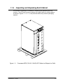
1.1.5 Inspecting and Unpacking Each Cabinet 1---3..................
2 Installing the UPS System 2---1................................
2.1 Preliminary Installation Information 2---1........................
2.2 UPS Cabinet Installation 2---2.................................
2.2.1 Unloading the Powerware BPIV (10 kVA---15 kVA)
UPS Cabinet from the Pallet 2---2.............................
2.2.2 Unloading the Powerware BPIV (10 kVA---15 kVA) Options
Cabinet with Optional Distribution Housing from the Pallet 2---5...
2.2.3 Unloading the Powerware BPIV (20 kVA---30 kVA)
UPS Cabinet from the Pallet 2---9.............................
2.2.4 Installing UPS External and Optional Remote Battery
Power Wiring 2---13..........................................
2.2.5 Installing Customer Connections 2---15.........................
2.2.6 Prepare for Installing Accessories 2---15........................
2.3 Battery Cabinet Installation 2---16..............................
2.3.1 Unloading the Battery Cabinet from the Pallet 2---16..............
2.3.2 Joining the Battery Cabinet to the UPS Cabinet 2---16............
2.3.3 Joining Additional Battery Cabinets 2---21.......................

iv
Powerware BPIV (10 kV A--30 kV A) Installation and Operation
164201406 Rev. C 013004
2.4 Options Cabinet Installation 2---23..............................
2.4.1 Unloading the Options Cabinet from the Pallet 2---23.............
2.4.2 Joining the Options Cabinet to the UPS Cabinet 2---23............
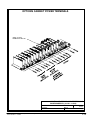
2.4.3 Installing Options Cabinet Internal and Optional Remote
Battery Power Wiring 2---28....................................
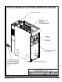
2.4.4 Installing Options Cabinet External Power Wiring 2---30...........
2.5 Initial Startup 2---32...........................................
2.6 Completing the Installation Checklist 2---32......................
2.6.1 Installation Checklist 2---33....................................
3 Installing and Connecting Batterie s 3---1.......................
3.1 Important Safety Instructions 3---1............................
3.2 Battery Type 3---2...........................................
3.3 Battery Installation 3---2......................................
3.3.1 Installing Internal Batteries in the UPS Cabinet 3---2.............
3.3.2 Installing Internal Batteries in the Battery Cabinet 3---5...........
3.4 Connecting Batteries 3---5....................................
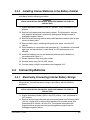
3.4.1 Electrically Connecting Internal Battery Strings 3---5.............
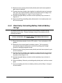
3.4.2 Electrically Connecting Battery Cabinet Battery Strings 3---6......
3.5 Installing and Connecting Remote Battery System 3---8..........
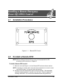
4 Installing a Remote Emergency Power Off (EPO) Control 4---1...
4.1 Installation Procedures 4---1..................................
4 . 2 To i n s t a l l a R e m o t e E P O : 4 --- 1................................
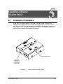
5 Installing a Remote Monitor Panel 5---1........................
5.1 Installation Procedures 5---1..................................
5 . 2 To i n s t a l l a n R M P : 5 --- 2......................................
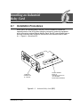
6 Installing an Industrial Relay Card 6---1........................
6.1 Installation Procedures 6---1..................................
6 . 2 To i n s t a l l a n I R C : 6 --- 2.......................................
Section II Operation
7
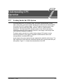
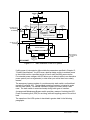
Understanding UPS Operation 7---1............................
7.1 Looking Inside the UPS System 7---1..........................
7 . 2 U P S M o d e s 7 --- 3............................................
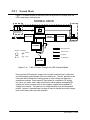
7.2.1 Normal Mode 7---4..........................................
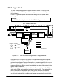
7.2.2 Bypass Mode 7---6..........................................
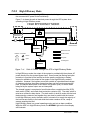
7.2.3 High Efficiency Mode 7---8...................................

v
Powerware BPIV (10 kV A--30 kV A) Installation and Operation
164201406 Rev. C 013004
7.2.4 Battery Mode 7---9..........................................
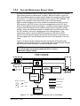
7.2.5 Test and Maintenance Bypass Modes 7---11.....................
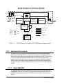
7.3 Functional Description 7---12..................................
7.3.1 Input Rectifier 7---12..........................................
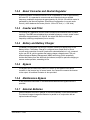
7.3.2 Boost Converter and Neutral Regulator 7---13....................
7.3.3 Inverter and Filter 7---13.......................................
7.3.4 Battery and Battery Charger 7---13.............................
7.3.5 Bypass 7---13................................................
7.3.6 Maintenance Bypass 7---13....................................
7.3.7 External Batteries 7---13.......................................
8 Operati onal Controls and Features 8---1........................
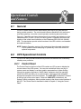
8.1 General 8---1...............................................
8.2 UPS Operational Controls 8---1...............................
8.2.1 Control Panel 8---1..........................................
8.2.2 UPS Circuit Breakers 8---4...................................
8.2.3 Smart LOAD OFF 8---4.......................................
8.2.4 Maintenance Bypass Switch 8---4.............................
8.2.5 Cold Start Switch 8---4.......................................
8.3 UPS Standard Features 8---4.................................
8.3.1 Customer Interface 8---4.....................................
8.3.2 Advanced Battery Management 8---5..........................
8.3.3 High Efficiency Mode 8---5...................................
8.3.4 Customer Convenience Outlet 8---5...........................
8.3.5 Installation Features 8---5....................................
8.3.6 Auto Restart 8---5...........................................
8.4 Options and Accessories 8---6................................
8.4.1 Remote EMERGENCY POWER OFF 8---6......................
8.4.2 Remote Monitor Panel 8---6..................................
8.4.3 Industrial Relay Card 8---6....................................
8.4.4 Options Cabinet 8---6........................................
8.4.5 Battery Cabinets 8---7.......................................
8.4.6 Parallel Cabinet 8---7........................................
8.4.7 Communications 8---7.......................................
8.5 Safety Considerations 8---8...................................
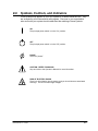
8.6 Symbols, Controls, and Indicators 8---9........................
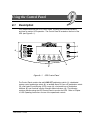
9 U s i n g t h e C o n t r o l P a n e l 9 --- 1..................................
9 . 1 D e s c r i p t i o n 9 --- 1............................................
9.2 Using the LCD Screen and Pushbuttons 9---2..................
9 . 3 U s i n g t h e M a i n M e n u 9 --- 3...................................
9.3.1 Mimic Screen 9---3..........................................
9.3.2 System Event Screens 9---4..................................

vi
Powerware BPIV (10 kV A--30 kV A) Installation and Operation
164201406 Rev. C 013004
9.3.3 Unit Meter Screens 9---6.....................................
9.3.4 System Meter Screens 9---9..................................
9.3.5 Setup Menu Level 0 Screens 9---11.............................
9.3.6 Setup Menu Level 1 Screens 9---13.............................
9.4 System Controls Screen 9---19.................................
9.4.1 Charger Controls Screen 9---21................................
9.5 Unit Shutdown Screen 9---22..................................
9.6 Reading the Status Indicators 9---23............................
10 UPS Operating Instructions 10---1.............................
10.1 Operation 10---1............................................
10.2 Starting the UPS in Normal Mode 10---1.......................
10.3 Starting the UPS in Bypass Mode 10---2.......................
10.4 Starting the Power Processing Unit 10---3.....................
10.5 Cold Starting the UPS 10---4.................................
10.6 Transfer from Normal to Bypass Mode 10---5...................
10.7 Transfer from Bypass to Normal Mode 10---6...................
10.8 Transfer from Normal to High Efficiency Mode 10---6............
10.9 Transfer from High Efficiency to Normal Mode 10---6............
10.10 Transfer from Normal to Bypass Mode with UPS Shutdown 10---7
10.11 UPS and Critical Load Shutdown 10---7.......................
10.12 UPS Maintenance Bypass Transfer 10---7......................
10.13 Options Cabinet Maintenance Bypass Transfer 10---8...........
10.14 Using the Power Distribution Module 10---8....................
10.15 Using the LOAD OFF Pushbutton 10---8.......................
10.15.1 To Use the LOAD OFF Pushbutton 10---8......................
10.16 Using the REMOTE EMERGENCY POWER OFF Switch 10---9...
10.16.1 To Use the REPO Switch 10---9...............................
11 U s i n g F e a t u r e s 1 1 --- 1.........................................
11.1 General 11---1...............................................
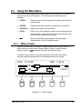
11.2 Building Alarm Monitoring 11---1...............................
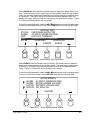
11.3 General Purpose Relay Contacts 11---1.........................
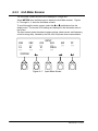
11.4 Optional R emote Monitor Panel 11---2..........................
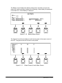
11.5 Optional Industrial Relay Card 11---3...........................
12 Responding to System Events 12---1...........................
12.1 General 12---1...............................................
12.2 System Event Horns 12---1....................................
12.3 System Event Lights 12---1....................................
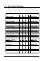
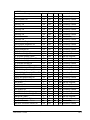
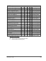
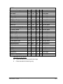
12.4 System Event Messages 12---2................................

vii
Powerware BPIV (10 kV A--30 kV A) Installation and Operation
164201406 Rev. C 013004
13 Communications 13---1.......................................
13.1 Description 13---1............................................
13.2 Standard Serial Port 13---1....................................
13.3 Configuring the Serial Port 13---2...............................
13.4 X-Slot Cards 13---2...........................................
13.5 Remote Notification 13---3.....................................
13.6 Remote Notification Features 13---4............................
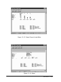
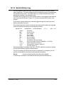
13.7 Terminal Mode 13---4.........................................
13.7.1 Display UPS Control Panel 13---4..............................
13.7.2 Event History Log 13---13......................................
14 Maintaining the UPS System 15---1............................
15.1 General 15---1...............................................
15.2 Important Safety Instructions 15---1.............................
15.3 Performing Preventive Maintenance 15---3.......................
15.4 Maintenance Training 15---4...................................
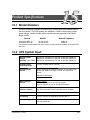
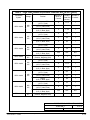
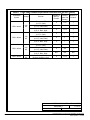
15 Product Specifications 16---1..................................
16.1 Model Numbers 16---1........................................
16.2 UPS System Input 16---1......................................
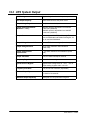
16.3 UPS System Output 16---2....................................
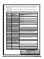
16.4 Environmental Specifications 16---3............................
A p p e n d i x A --- C u s t o m e r I n f o r m a t i o n A --- 1.........................
Warranty W---1..................................................

viii
Powerware BPIV (10 kV A--30 kV A) Installation and Operation
164201406 Rev. C 013004
List of Figures
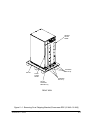
F i g u r e 1 --- 1 . Po w e r wa r e B P I V ( 1 0 k VA --- 1 5 k VA )
Cabinet as Shipped on Pallet 1---3...............................
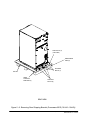
F i g u r e 1 --- 2 . Po w e r wa r e B P I V ( 2 0 k VA --- 3 0 k VA )
Cabinet as Shipped on Pallet 1---4...............................
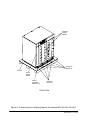
Figure 2---1. Removing Front Shipping Bracket
( Po w e r w a r e B P I V ( 1 0 k V A --- 1 5 k V A ) ) 2 --- 3.........................
Figure 2---2. Removing Rear Shipping Bracket
( Po w e r w a r e B P I V ( 1 0 k V A --- 1 5 k V A ) ) 2 --- 4.........................
Figure 2---3. Removing Options Cabinet Front Shipping Bracket
( Po w e r w a r e B P I V ( 1 0 k V A --- 1 5 k V A ) ) 2 --- 7.........................
Figure 2---4. Removing Options Cabinet Rear Shipping Bracket
( Po w e r w a r e B P I V ( 1 0 k V A --- 1 5 k V A ) ) 2 --- 8.........................
Figure 2---5. Removing Front Shipping Bracket
( Po w e r w a r e B P I V ( 2 0 k V A --- 3 0 k V A ) ) 2 --- 1 0.........................
Figure 2---6. Removing Rear Shipping Bracket
( Po w e r w a r e B P I V ( 2 0 k V A --- 3 0 k V A ) ) 2 --- 1 1.........................
F i g u r e 2 --- 7 . B a t t e r y C a b i n e t I n s t a l l a t i o n --- P o we r w a r e B P I V ( 1 0 k VA --- 1 5 k VA )
(Non–Permanent Mounting) 2---17.................................
F i g u r e 2 --- 8 . B a t t e r y C a b i n e t I n s t a l l a t i o n --- P o we r w a r e B P I V ( 1 0 k VA --- 1 5 k VA )
(Permanent Mounting) 2---18.....................................
F i g u r e 2 --- 9 . B a t t e r y C a b i n e t I n s t a l l a t i o n --- P o we r w a r e B P I V ( 2 0 k VA --- 3 0 k VA )
(Non–Permanent Mounting) 2---19.................................
F i g u r e 2 --- 1 0 . B a t t e r y C a b i n e t I n s t a l l a t i o n --- P o we r w a r e B P I V ( 2 0 k VA --- 3 0 k VA )
(Permanent Mounting) 2---20.....................................
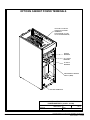
F i g u r e 2 --- 1 1 . O p t i o n s C a b i n e t I n s t a l l a t i o n --- P o w e r w a r e B P I V ( 1 0 k VA --- 1 5 k VA )
(Non–Permanent Mounting) 2---24.................................
F i g u r e 2 --- 1 2 . O p t i o n s C a b i n e t I n s t a l l a t i o n --- P o w e r w a r e B P I V ( 1 0 k VA --- 1 5 k VA )
(Permanent Mounting) 2---25.....................................
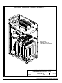
F i g u r e 2 --- 1 3 . O p t i o n s C a b i n e t I n s t a l l a t i o n --- P o w e r w a r e B P I V ( 2 0 k VA --- 3 0 k VA )
(Non–Permanent Mounting) 2---26.................................
F i g u r e 2 --- 1 4 . O p t i o n s C a b i n e t I n s t a l l a t i o n --- P o w e r w a r e B P I V ( 2 0 k VA --- 3 0 k VA )
(Permanent Mounting) 2---27.....................................
F i g u r e 3 --- 1 . B a t t e r y S c h e m a t i c --- Po w e r w a r e B P I V ( 1 0 k V A --- 1 5 k V A ) U P S
and Battery Cabinet 3---3........................................
F i g u r e 3 --- 2 . B a t t e r y S c h e m a t i c --- Po w e r w a r e B P I V ( 2 0 k V A --- 3 0 k V A ) U P S 3 --- 4...
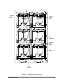
Figure 3---3. Battery String Connection 3---7..................................
F i g u r e 4 --- 1 . R e m o t e E P O C o n t r o l 4 --- 1......................................
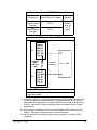
Figure 4---2. Remote EPO Control
(inside view of cover and enclosure bottom) 4---2..................

ix
Powerware BPIV (10 kV A--30 kV A) Installation and Operation
164201406 Rev. C 013004
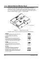
F i g u r e 5 --- 1 . R e m o t e M o n i t o r Pa n e l ( R M P ) 5 --- 1...............................
Figure 5---2 Remote Monitor Card 5---3......................................
F i g u r e 5 --- 3 . R e m o t e M o n i t o r Pa n e l ( R M P ) --- To p I n t e r n a l V i e w 5 --- 3.............
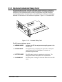
F i g u r e 6 --- 1 I n d u s t r i a l R e l a y C a r d 6 --- 1.......................................
F i g u r e 7 --- 1 . M a i n E l e m e n t s o f t h e U P S S y s t e m 7 --- 2...........................
Figure 7---2. Path of Current Through the UPS in Normal Mode 7---4.............
Figure 7---3. Path of Current Through the UPS in Bypass Mode 7---6.............
Figure 7---4. Path of Current Through the UPS in High Efficiency Mode 7---8......
Figure 7---5. Path of Current Through the UPS in Battery Mode 7---9.............
Figure 7---6. Path of Current Through the UPS in Test Mode 7---11................
Figure 7---7. Path of Current Through the UPS in Maintenance Bypass Mode 7---12.
F i g u r e 8 --- 1 . Po w e r wa r e B P I V ( 1 0 k VA --- 1 5 k VA ) U P S C o n t r o l s a n d I n d i c a t o r s 8 --- 2.
F i g u r e 8 --- 2 . Po w e r wa r e B P I V ( 2 0 k VA --- 3 0 k VA ) U P S C o n t r o l s a n d I n d i c a t o r s 8 --- 3.
F i g u r e 9 --- 1 . U P S C o n t r o l P a n e l 9 --- 1.........................................
F i g u r e 9 --- 2 . Pa r t s o f t h e L C D S c r e e n 9 --- 2....................................
F i g u r e 9 --- 3 . M i m i c S c r e e n 9 --- 3.............................................
F i g u r e 9 --- 4 . E v e n t S i m p l e H i s t o r y L o g S c r e e n 9 --- 4............................
F i g u r e 9 --- 5 . E v e n t H i s t o r y ( A l l ) L o g S c r e e n 9 --- 5...............................
Figure 9---6. Active System Events Screen 9---5...............................
Figure 9---7. Input Meter Screen 9---6........................................
F i g u r e 9 --- 8 . O u t p u t M e t e r S c r e e n 9 --- 7.......................................
F i g u r e 9 --- 9 . B y p a s s M e t e r S c r e e n 9 --- 7......................................
F i g u r e 9 --- 1 0 . B a t t e r y M e t e r S c r e e n 9 --- 8......................................
F i g u r e 9 --- 1 1 . O u t p u t C u r r e n t ( L o a d ) M e t e r S c r e e n 9 --- 8.........................
Figure 9---12. System Input Meter Screen 9---9.................................
F i g u r e 9 --- 1 3 . S y s t e m O u t p u t M e t e r S c r e e n 9 --- 1 0...............................
Figure 9---14. System Bypass Meter Screen 9---10...............................
Figure 9---15. Setup Menu Level 0 Screen 9---11.................................
Figure 9---16. Contrast Adjust Menu Screen 9---11...............................
F i g u r e 9 --- 1 7 . Ve r s i o n s S c r e e n 9 --- 1 2...........................................
F i g u r e 9 --- 1 8 . U n i t Ty p e S c r e e n 9 --- 1 2..........................................
F i g u r e 9 --- 1 9 . E n t e r P a s s w o r d S c r e e n 9 --- 1 3....................................
Figure 9---20. Setup Menu Level 1 Screen 9---14.................................
F i g u r e 9 --- 2 1 . C h a n g e Pa s s w o r d S c r e e n 9 --- 1 5..................................
F i g u r e 9 --- 2 2 . C h a n g e Pa s s w o r d S a v e S c r e e n 9 --- 1 6.............................
F i g u r e 9 --- 2 3 . D a t e & T i m e S c r e e n 9 --- 1 7.......................................

x
Powerware BPIV (10 kV A--30 kV A) Installation and Operation
164201406 Rev. C 013004
F i g u r e 9 --- 2 4 . Po r t S e t u p S c r e e n 9 --- 1 8.........................................
Figure 9---25. System Controls Screen in Normal Mode 9---19.....................
Figure 9---26. System Controls Screen in High Efficiency Mode 9---20..............
F i g u r e 9 --- 2 7 . C h a r g e r C o n t r o l s S c r e e n 9 --- 2 1...................................
F i g u r e 9 --- 2 8 . S h u t d o w n S c r e e n 9 --- 22.........................................
F i g u r e 1 1 --- 1 . R e m o t e M o n i t o r Pa n e l 1 1 --- 2.....................................
F i g u r e 1 1 --- 2 . I n d u s t r i a l R e l a y C a r d 1 1 --- 3.......................................
Figure 13---1. Serial Port Pin Assignments 13---1.................................
F i g u r e 1 3 --- 2 . O p t i o n a l X- S l o t C a r d s 1 3 --- 3......................................
F i g u r e 1 3 --- 3 . M a i n S c r e e n --- U P S N o r m a l M i m i c 1 3 --- 5..........................
F i g u r e 1 3 --- 4 . M a i n S c r e e n --- U P S O n B a t t e r y M i mi c 1 3 --- 5.......................
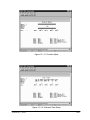
F i g u r e 1 3 --- 5 . M a i n S c r e e n --- U P S O n B y p a s s M i m i c 1 3 --- 6.......................
F i g u r e 1 3 --- 6 . S y s t e m C o n t r o l s 1 3 --- 6..........................................
F i g u r e 1 3 --- 7 . L o a d O f f 1 3 --- 7..................................................
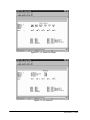
F i g u r e 1 3 --- 8 . E v e n t s --- H i s t o r y 1 3 --- 7..........................................
F i g u r e 1 3 --- 9 . E v e n t s --- A c t i v e 1 3 --- 8...........................................
F i g u r e 1 3 --- 1 0 . I n p u t M e t e r 1 3 --- 8...............................................
F i g u r e 1 3 --- 1 1 . O u t p u t M e t e r 1 3 --- 9.............................................
F i g u r e 1 3 --- 1 2 . B y p a s s M e t e r 1 3 --- 9.............................................
F i g u r e 1 3 --- 1 3 . O u t p u t C u r r e n t ( L o a d ) M e t e r 1 3 --- 1 0................................
F i g u r e 1 3 --- 1 4 . S e t u p 1 3 --- 1 0....................................................
Figure 13---15. Contrast Adjust 13---11...........................................
Figure 13---16. Date and Time Setup 13---11......................................
Figure 13---17. Serial Port Setup 13---12..........................................
Figure 13---18. Versions 13---12..................................................
F i g u r e 1 3 --- 1 9 . E v e n t H i s t o r y L o g 13 --- 1 4.........................................

xi
Powerware BPIV (10 kV A--30 kV A) Installation and Operation
164201406 Rev. C 013004
List of Tables
Ta b l e 4 --- 1 . R e m o t e E P O W i r e Te r m i n a t i o n s 4 --- 3.................................
Ta b l e 4 --- 2 . R e m o t e E P O 4 --- 3.................................................
Ta b l e 5 --- 1 . R M P W i r e Te r mi n a t i o n s 5 --- 2........................................
Ta b l e 6 --- 1 . I R C W i r e Te r m i n a t i o n s 6 --- 2.........................................
Ta b l e 1 3 --- 1 . P i n A s s i g n m e n t s f o r S e r i a l Po r t ( D B --- 9 ) 1 3 --- 3.........................
Ta b l e 1 3 --- 2 . S e r i a l C o m m u n i c a t i o n s P o r t 1 3 --- 3...................................

xii
Powerware BPIV (10 kV A--30 kV A) Installation and Operation
164201406 Rev. C 013004
This Page Intentionally Left Blank.

xiii
Powerware BPIV (10 kV A--30 kV A) Installation and Operation
164201406 Rev. C 013004
Introduction
Powerware BPIV UPS true double conversion online power protection can be utilized
to prevent loss of valuable electronic information, minimize equipment downtime,
and/or minimize the adverse effect on equipment production due to unexpected power
problems.
The Powerware UPS System continually monitors incoming electrical power and
removes the surges, spikes, sags, and other irregularities that are inherent in
commercial utility power. Working with your building’s electrical system, the UPS
System supplies clean, consistent power that your sensitive electronic equipment
requires for reliable operation. During brownouts, blackouts, and other power
interruptions, internal and optional external battery strings provide emergency power to
safeguard your operation.
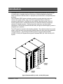
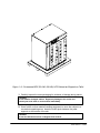
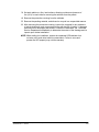
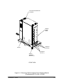
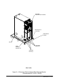
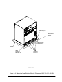
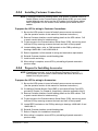
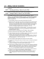
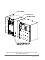
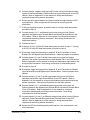
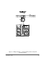
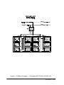
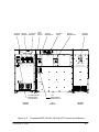
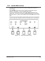
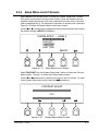
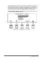
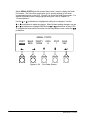
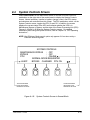
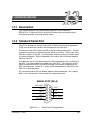
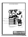
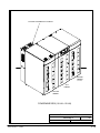
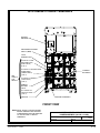
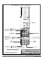
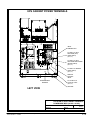
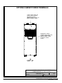
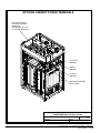
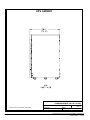
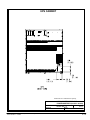
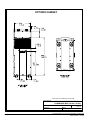
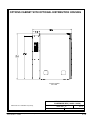
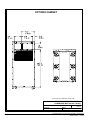
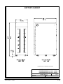
The UPS system is housed in free-standing cabinets. The cabinet sections line up and
match in style and color, and have safety shields behind the front panels for hazardous
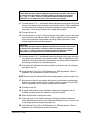
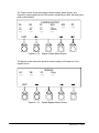
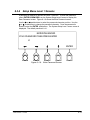
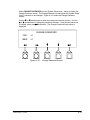
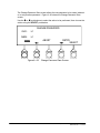
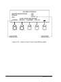
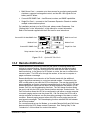
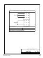
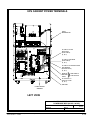
voltage protection. The following illustrations depict a typical Powerware BPIV
(10 kVA---15 kVA) UPS System and a typical Powerware BPIV (20 kVA---30 kVA) UPS
System
BATTERY
CABINET
UPS
CABINET
OPTIONS
CABINET
(OPTIONAL)
(OPTIONAL)
Ty p i c a l P o w e r w a r e B P I V ( 1 0 k V A --- 1 5 k V A ) U P S S y s t e m

xiv
Powerware BPIV (10 kV A--30 kV A) Installation and Operation
164201406 Rev. C 013004
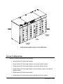
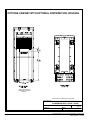
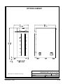
UPS
CABINET
BATTERY
CABINET
OPTIONS
CABINET
(OPTIONAL)
(OPTIONAL)
Ty p i c a l P o w e r w a r e B P I V ( 2 0 k V A --- 3 0 k V A ) U P S S y s t e m
System Configurations
These UPS system configurations are possible:
• Single Module UPS with integral battery
• Single Module UPS with integral battery and optional options cabinet
• Single Module UPS with integral battery and optional battery cabinet
• Single Module UPS with integral battery, optional battery cabinet, and optional
options cabinet
• Single Module UPS with remote battery
• Single Module UPS with remote battery and optional options cabinet

xv
Powerware BPIV (10 kV A--30 kV A) Installation and Operation
164201406 Rev. C 013004
• Parallel System with one to four UPS modules with remo te battery and optional
options cabinet
• Parallel System with one to four UPS modules and integral battery
• Parallel System with one to four UPS modules, integral battery, and optional
battery cabinet
• Parallel System with one to four UPS modules and remote battery
You can enhance any of these system configurations by adding an optional
accessories, such as a Remote Emergency Power Off (EPO) control, a Remote Monitor
Panel (RMP), and X-Slot
t communications connectivity features.
Using This Manual
Your UPS functions automatically and requires very little attention during normal
operation. However, you should read and understand the procedures described in this
manual to ensure trouble-free operation. In particular, you should be thoroughly
familiar with the Remote Emergency Power Off procedure described in Chapter 10 of
this manual.
The information in this manual is divided into the sections and chapters listed.
The system you are installing dictates which parts of this manual you should read.
Everyone should read, at a minimum, the Introduction, Chapters 1, 2, 8, 9, and 10.
Introduction
The Introduction provides a brief description of the UPS system, a description of the
content of each chapter, text conventions used in the manual, safety, and reference
information.
Section I
• Chapter 1 -- Getting Started -- tells you how to prepare your site for the
installation of your UPS system. It discusses equipment environmental
requirements, inspecting, and unpacking cabinets.
• Chapter 2 -- Installing the UPS System -- describes how to install the UPS
cabinets and optional equipment.
• Chapter 3 -- Installing Batteries -- provides battery safety, installation and
connection information.
• Chapter 4 -- Installing a Remote EPO Control -- contains information for
installing the optional Remo te Emergen cy Power Off (EPO) control.
• Chapter 5 -- Installing a Remote Monitor Panel -- contains information for
installing the optional Remote Monitor Panel (RMP).
• Chapter 6 -- Installing an Industrial Relay Card-- contains information for
installing the optional Industrial Relay Card (IRC).
Section II
• Chapter 7 -- Understanding UPS Operation -- provides information on
understanding UPS operation.

xvi
Powerware BPIV (10 kV A--30 kV A) Installation and Operation
164201406 Rev. C 013004
• Chapter 8 -- Operational Controls and Features -- describes the standard
and optional operational features and controls of the UPS system.
• Chapter 9 -- Using the Control Panel -- describes the controls and indicators
found on the Control Panel and shows the various information screens
displayed on the LCD screen.
• Chapter 10 -- UPS Operating Instructions -- contains startup and shutdown
procedures for the UPS system.
• Chapter 11 -- Using Features and Options -- contains descriptions and
instructions for the UPS system features and options.
• Chapter 12 -- Responding to System Events -- lists all the alarm messages
and notices that occur during operation of the UPS system.
• Chapter 13 -- Communications -- describesthecommunicationsfeaturesof
the UPS system.
• Chapter 14 -- Maintaining the UPS System -- contains maintenance
instructions for the UPS system.
• Chapter 15 -- Product Specifications -- provides detailed specifications for
the UPS system.
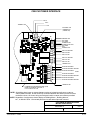
• Appendix A - -Customer Information -- contains important information on
wiring requirements and recommendations, and important diagrams of the
cabinet’s mechanical details and electrical access.
• Warranty -- provides the Powerware warranty for this product.
Read through each procedure before you begin. Perform only those procedures
that apply to the UPS system you are installing or operating.
Conventions Used in This Manual
The text in this manual uses these conventions:
• Bold type highlights important concepts in discussions, key terms in
procedures, and menu options.
• Italic type highlights notes and new terms where they are defined.
• Rectangular boxes containing bold type are warnings or cautions that pertain to
the UPS system or its electrical connections.
In this manual, the term UPS refers only to the UPS cabinet and its internal elements.
The term UPS system refers to the entire power protection system—the UPS modules,
battery strings and options or accessories installed.

xvii
Powerware BPIV (10 kV A--30 kV A) Installation and Operation
164201406 Rev. C 013004
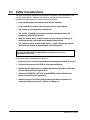
Safety Considerations
The UPS cabinet is designed for industrial or computer room applications, and contain
safety shields behind the doors. However, the UPS system is a sophisticated power
system and should be handled with appropriate care, following these guidelines:
• Keep surroundings clean and free from excess moisture.
• Do not operate the UPS system close to gas or electric heat sources.
• The system is not intended for outdoor use.
• The operating environment should be maintained within the parameters
stated in this manual.
• Keep the cabinet doors closed and locked to ensure proper cooling airflow
and to protect personnel from dangerous voltages inside the unit.
• The UPS system contains its own power source. Lethal voltages are
present even when the UPS is disconnected from utility power.
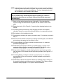
WARNING:
Only AUTHORIZED SERVICE PERSONNEL should perform maintenance on or
service the UPS system.
If service or routine maintenance is required:
• Ensure all power is disconnected before performing installation or service.
• Ensure the area around the UPS system is clean and uncluttered.
• Battery maintenance or battery replacement should be performed only by
authorized service personnel.
• Observe all DANGER, CAUTION, and WARNING notices affixed to the
inside and outside of the equipment.

xviii
Powerware BPIV (10 kV A--30 kV A) Installation and Operation
164201406 Rev. C 013004
For More Information
This manual describes how to install and operate the UPS modules. For more
information about the installation and operation of a Parallel System, refer to the
following:
164201409 Powerware
BPIV Parallel Cabinet Installation and Operation
Manual
The Installation section, provides installation instructions for the
Parall el cabinet. Site preparation, planning for installation, and
wiring and safety information are supplied. Detailed illustrations
of the cabinet, including dimensional and connection point
drawings are provided.
The Operation section, explains the functions of the Parallel
System; ; provides procedures for operating the Parallel System,
and information about maintenance and responding to system
events.
Contact your local Invensys Powerware Field Service office for information on how
to obtain copies of this manual.
Getting Help
If you need to schedule initial startup, need regional locations and telephone numbers,
have a question about any of the information in this manual, or have a question this
manual does not answer, please call Powerware at:
United States 1-800-843-9433
Canada 1-800-461-9166
Outside the U.S. Call your local representative

Powerware BPIV (10 kV A--30 kV A) Installation and Operation
164201406 Rev. C 013004
Section I
Installation

Powerware BPIV (10 kV A--30 kV A) Installation and Operation
164201406 Rev. C 013004
This Page Intentionally Left Blank.
Page is loading ...
Page is loading ...
Page is loading ...
Page is loading ...
Page is loading ...
Page is loading ...
Page is loading ...
Page is loading ...
Page is loading ...
Page is loading ...
Page is loading ...
Page is loading ...
Page is loading ...
Page is loading ...
Page is loading ...
Page is loading ...
Page is loading ...
Page is loading ...
Page is loading ...
Page is loading ...
Page is loading ...
Page is loading ...
Page is loading ...
Page is loading ...
Page is loading ...
Page is loading ...
Page is loading ...
Page is loading ...
Page is loading ...
Page is loading ...
Page is loading ...
Page is loading ...
Page is loading ...
Page is loading ...
Page is loading ...
Page is loading ...
Page is loading ...
Page is loading ...
Page is loading ...
Page is loading ...
Page is loading ...
Page is loading ...
Page is loading ...
Page is loading ...
Page is loading ...
Page is loading ...
Page is loading ...
Page is loading ...
Page is loading ...
Page is loading ...
Page is loading ...
Page is loading ...
Page is loading ...
Page is loading ...
Page is loading ...
Page is loading ...
Page is loading ...
Page is loading ...
Page is loading ...
Page is loading ...
Page is loading ...
Page is loading ...
Page is loading ...
Page is loading ...
Page is loading ...
Page is loading ...
Page is loading ...
Page is loading ...
Page is loading ...
Page is loading ...
Page is loading ...
Page is loading ...
Page is loading ...
Page is loading ...
Page is loading ...
Page is loading ...
Page is loading ...
Page is loading ...
Page is loading ...
Page is loading ...
Page is loading ...
Page is loading ...
Page is loading ...
Page is loading ...
Page is loading ...
Page is loading ...
Page is loading ...
Page is loading ...
Page is loading ...
Page is loading ...
Page is loading ...
Page is loading ...
Page is loading ...
Page is loading ...
Page is loading ...
Page is loading ...
Page is loading ...
Page is loading ...
Page is loading ...
Page is loading ...
Page is loading ...
Page is loading ...
Page is loading ...
Page is loading ...
Page is loading ...
Page is loading ...
Page is loading ...
Page is loading ...
Page is loading ...
Page is loading ...
Page is loading ...
Page is loading ...
Page is loading ...
Page is loading ...
Page is loading ...
Page is loading ...
Page is loading ...
Page is loading ...
Page is loading ...
Page is loading ...
Page is loading ...
Page is loading ...
Page is loading ...
Page is loading ...
Page is loading ...
Page is loading ...
Page is loading ...
Page is loading ...
Page is loading ...
Page is loading ...
Page is loading ...
Page is loading ...
Page is loading ...
Page is loading ...
Page is loading ...
Page is loading ...
Page is loading ...
Page is loading ...
Page is loading ...
Page is loading ...
Page is loading ...
Page is loading ...
Page is loading ...
Page is loading ...
Page is loading ...
Page is loading ...
Page is loading ...
Page is loading ...
Page is loading ...
Page is loading ...
Page is loading ...
Page is loading ...
Page is loading ...
Page is loading ...
Page is loading ...
Page is loading ...
Page is loading ...
Page is loading ...
Page is loading ...
Page is loading ...
Page is loading ...
Page is loading ...
Page is loading ...
Page is loading ...
Page is loading ...
Page is loading ...
Page is loading ...
Page is loading ...
Page is loading ...
Page is loading ...
Page is loading ...
Page is loading ...
Page is loading ...
Page is loading ...
Page is loading ...
Page is loading ...
Page is loading ...
Page is loading ...
Page is loading ...
Page is loading ...
Page is loading ...
Page is loading ...
Page is loading ...
Page is loading ...
Page is loading ...
Page is loading ...
Page is loading ...
Page is loading ...
Page is loading ...
Page is loading ...
Page is loading ...
Page is loading ...
Page is loading ...
Page is loading ...
Page is loading ...
Page is loading ...
Page is loading ...
Page is loading ...
Page is loading ...
Page is loading ...
Page is loading ...
Page is loading ...
Page is loading ...
Page is loading ...
Page is loading ...
Page is loading ...
Page is loading ...
Page is loading ...
Page is loading ...
Page is loading ...
Page is loading ...
Page is loading ...
Page is loading ...
Page is loading ...
Page is loading ...
Page is loading ...
Page is loading ...
Page is loading ...
Page is loading ...
Page is loading ...
Page is loading ...
Page is loading ...
Page is loading ...
Page is loading ...
Page is loading ...
Page is loading ...
Page is loading ...
Page is loading ...
Page is loading ...
Page is loading ...
Page is loading ...
Page is loading ...
Page is loading ...
Page is loading ...
Page is loading ...
Page is loading ...
Page is loading ...
Page is loading ...
Page is loading ...
Page is loading ...
Page is loading ...
Page is loading ...
Page is loading ...
Page is loading ...
-
 1
1
-
 2
2
-
 3
3
-
 4
4
-
 5
5
-
 6
6
-
 7
7
-
 8
8
-
 9
9
-
 10
10
-
 11
11
-
 12
12
-
 13
13
-
 14
14
-
 15
15
-
 16
16
-
 17
17
-
 18
18
-
 19
19
-
 20
20
-
 21
21
-
 22
22
-
 23
23
-
 24
24
-
 25
25
-
 26
26
-
 27
27
-
 28
28
-
 29
29
-
 30
30
-
 31
31
-
 32
32
-
 33
33
-
 34
34
-
 35
35
-
 36
36
-
 37
37
-
 38
38
-
 39
39
-
 40
40
-
 41
41
-
 42
42
-
 43
43
-
 44
44
-
 45
45
-
 46
46
-
 47
47
-
 48
48
-
 49
49
-
 50
50
-
 51
51
-
 52
52
-
 53
53
-
 54
54
-
 55
55
-
 56
56
-
 57
57
-
 58
58
-
 59
59
-
 60
60
-
 61
61
-
 62
62
-
 63
63
-
 64
64
-
 65
65
-
 66
66
-
 67
67
-
 68
68
-
 69
69
-
 70
70
-
 71
71
-
 72
72
-
 73
73
-
 74
74
-
 75
75
-
 76
76
-
 77
77
-
 78
78
-
 79
79
-
 80
80
-
 81
81
-
 82
82
-
 83
83
-
 84
84
-
 85
85
-
 86
86
-
 87
87
-
 88
88
-
 89
89
-
 90
90
-
 91
91
-
 92
92
-
 93
93
-
 94
94
-
 95
95
-
 96
96
-
 97
97
-
 98
98
-
 99
99
-
 100
100
-
 101
101
-
 102
102
-
 103
103
-
 104
104
-
 105
105
-
 106
106
-
 107
107
-
 108
108
-
 109
109
-
 110
110
-
 111
111
-
 112
112
-
 113
113
-
 114
114
-
 115
115
-
 116
116
-
 117
117
-
 118
118
-
 119
119
-
 120
120
-
 121
121
-
 122
122
-
 123
123
-
 124
124
-
 125
125
-
 126
126
-
 127
127
-
 128
128
-
 129
129
-
 130
130
-
 131
131
-
 132
132
-
 133
133
-
 134
134
-
 135
135
-
 136
136
-
 137
137
-
 138
138
-
 139
139
-
 140
140
-
 141
141
-
 142
142
-
 143
143
-
 144
144
-
 145
145
-
 146
146
-
 147
147
-
 148
148
-
 149
149
-
 150
150
-
 151
151
-
 152
152
-
 153
153
-
 154
154
-
 155
155
-
 156
156
-
 157
157
-
 158
158
-
 159
159
-
 160
160
-
 161
161
-
 162
162
-
 163
163
-
 164
164
-
 165
165
-
 166
166
-
 167
167
-
 168
168
-
 169
169
-
 170
170
-
 171
171
-
 172
172
-
 173
173
-
 174
174
-
 175
175
-
 176
176
-
 177
177
-
 178
178
-
 179
179
-
 180
180
-
 181
181
-
 182
182
-
 183
183
-
 184
184
-
 185
185
-
 186
186
-
 187
187
-
 188
188
-
 189
189
-
 190
190
-
 191
191
-
 192
192
-
 193
193
-
 194
194
-
 195
195
-
 196
196
-
 197
197
-
 198
198
-
 199
199
-
 200
200
-
 201
201
-
 202
202
-
 203
203
-
 204
204
-
 205
205
-
 206
206
-
 207
207
-
 208
208
-
 209
209
-
 210
210
-
 211
211
-
 212
212
-
 213
213
-
 214
214
-
 215
215
-
 216
216
-
 217
217
-
 218
218
-
 219
219
-
 220
220
-
 221
221
-
 222
222
-
 223
223
-
 224
224
-
 225
225
-
 226
226
-
 227
227
-
 228
228
-
 229
229
-
 230
230
-
 231
231
-
 232
232
-
 233
233
-
 234
234
-
 235
235
-
 236
236
-
 237
237
-
 238
238
-
 239
239
-
 240
240
-
 241
241
-
 242
242
-
 243
243
-
 244
244
-
 245
245
-
 246
246
-
 247
247
-
 248
248
-
 249
249
-
 250
250
-
 251
251
-
 252
252
-
 253
253
-
 254
254
-
 255
255
-
 256
256
-
 257
257
-
 258
258
-
 259
259
-
 260
260
-
 261
261
-
 262
262
-
 263
263
-
 264
264


Powerware BPIV Installation & Operation Manual
- Type
- Installation & Operation Manual
Ask a question and I''ll find the answer in the document
Finding information in a document is now easier with AI
Related papers
-
Powerware BPIV 30 kVA Installation & Operation Manual
-
-
-
AEG Powerware 9155 30 kVA User manual
-
-
-
-
-
-
Eaton 100160 kVA User manual
Other documents
-
Minuteman ED6000RMXFMR User manual
-
 Kval 990-F4 Owner's manual
-
Toshiba Power Supply 4200FA XT2 User manual
-
Leviton R24BD-L24 Installation guide
-
Rittal RimatriX5 7857.430 Installation guide
-
-
Rittal 7857.483 User manual
-
 Leonics NBP-8KS User manual
-
-

