Page is loading ...

06/05/13 AERCO International, Inc. • 100 Oritani Dr. • Blauvelt, NY 10913 • Ph: 800-526- 0288 Page 1 of 112
GF-115-C
OMM-0084_0D
.
Revised: 06/05/2013
E8 Controller and BCM
For
Modulex MLX & EXT Boilers
For Modulating, Condensing,
Hot Water Boiler Models:
• MLX-303
• MLX-454
• MLX-606
• MLX-757
• MLX-909
• MLX-1060
• EXT 321
• EXT 481
• EXT 641
• EXT 802
• EXT 962
• EXT 1123
• EXT 1530
• EXT 1912
• EXT 2295
• EXT 2677
• EXT 3060
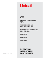
E8 Controller for MLX & EXT Series Boilers
Boiler Communications Module (BCM)
for MLX and EXT Series Boilers
USER MANUAL
Installation, Operation, and Maintenance

06/05/13 AERCO International, Inc. • 100 Oritani Dr. • Blauvelt, NY 10913 • Ph: 800-526- 0288 Page 2 of 112
GF-115-C
Modulex E8 Controller and BCM
Operations and Maintenance Manual
OMM-0084_0D
Disclaimer
The information contained in this manual is subject to change without notice from AERCO International,
Inc. AERCO makes no warranty of any kind with respect to this material, including but not limited to
implied warranties of merchantability and fitness for a particular application. AERCO International is not
liable for errors appearing in this manual. Nor for incidental or consequential damages occurring in
connection with the furnishing, performance, or use of this material.
Technical Support:
(Mon–Fri, 8am-5pm EST)
1-800-526-0288
www.aerco.com
AERCO International, Inc. • 100 Oritani Dr. • Blauvelt, New York 10913 • Phone: 800-526-0288

06/05/13 AERCO International, Inc. • 100 Oritani Dr. • Blauvelt, NY 10913 • Ph: 800-526- 0288 Page 3 of 112
GF-115-C
OMM-0084_0D
Table of Contents
Table of Contents .......................................................................................... 3
1. INTRODUCTION ................................................................................ 7
1.1 Safety and Warnings ........................................................................................ 7
2. E8 CONTROLLER AND BCM DESCRIPTION ..................................... 9
2.1 E8 Controller Features And Functions ........................................................... 9
2.2 BCM Features And Functions ....................................................................... 10
3. E8 CONTROLLER OPERATION ....................................................... 11
3.1 NORMAL Mode Operation (Door Closed)..................................................... 11
3.1.1 NORMAL Mode Display Functions ................................................................... 11
3.1.2 HEATING Mode Selection (in NORMAL Mode) ............................................. 12
3.1.3 MENU Mode Operation (Door Open) ................................................................ 12
3.2 Software Menus .............................................................................................. 13
3.2.1 Basic Menu/Sub-Menu Navigation and Selection .............................................. 15
3.2.2 Basic Parameter Navigation, Selection, and Revision ........................................ 16
4. E8 CONTROLLER MENUS AND SUB-MENUS ................................. 17
4.1 DISPLAY Menu ............................................................................................... 18
4.2 USER Menu ..................................................................................................... 21
4.3 TIME PROGRAM Menu and Sun-Menus ....................................................... 24
4.4 EXPERT Menu and Sub-Menus ..................................................................... 25
4.4.1 Available V-Curve Preset Voltage Curves for 0 – 10 Volt Input ....................... 31
4.5 EXPERT HS Menu (Not Used) ...................................................................... 31
4.6 GENERAL Menu ............................................................................................. 32
4.6.1 DATE / TIME Menu ........................................................................................... 32
4.6.2 SERVICE Menu .................................................................................................. 34
4.7 E8 Controller Initial Startup ........................................................................... 37
4.7.1 CAP/MODULE Function (Maximum Kilowatts per Burner) ............................ 39
4.7.1 Available Settings for Relay Functions 1 – 4 ...................................................... 40
5. E8 OPERATING MODE: Set-up and Programming ............................. 42
5.1 Indoor/Outdoor Reset Mode .......................................................................... 42
5.1.1 Wiring Connections............................................................................................. 42
5.1.2 Indoor/Outdoor Reset Operation Configuration ................................................. 42
5.1.3 Viewing the Boiler Setpoint ................................................................................ 44
5.2 Constant Set Point Mode ............................................................................... 44
5.2.1 Wiring Connections............................................................................................. 45
5.2.2 Constant Setpoint Mode Configuration............................................................... 45
5.2.3 Viewing Constant Set Point ................................................................................ 45
5.2.4 Configuring Set Point High and Low Limits Per Outside Temperature Sensor . 45

06/05/13 AERCO International, Inc. • 100 Oritani Dr. • Blauvelt, NY 10913 • Ph: 800-526- 0288 Page 4 of 112
GF-115-C
Modulex E8 Controller and BCM
Operations and Maintenance Manual
OMM-0084_0D
5.3 0 to 10 Volt Remote Set Point Mode ............................................................. 48
5.3.1 Remote Signal Source Wiring Connections ........................................................ 48
5.3.2 Configuring Remote Signal Source..................................................................... 49
5.3.3 Setting the Voltage and Set Point Limits for U1/U2 and T1/T2 ......................... 50
5.3.4 Setting the Curve 11-UO Voltage ....................................................................... 51
5.3.5 Viewing the Set Point .......................................................................................... 52
5.4 Domestic Hot Water Operation Using A Tank Sensor ................................ 52
5.4.1 Sensor Wiring Connections ................................................................................. 52
5.4.2 Configuring the Controller for DHW With a Tank Sensor ................................. 53
5.4.3 Setting the DHW Set Point ................................................................................. 54
5.4.4 Displaying Temperatures Associated With DHW .............................................. 55
5.5 DHW Operation Using an Aquastat .............................................................. 56
5.5.1 Sensor Wiring Connections ................................................................................. 56
5.5.2 Configuring the Controller for DHW With an Aquastat ..................................... 56
5.5.3 Setting the DHW Set Point ................................................................................. 56
5.5.4 Displaying Temperatures Associated With DHW .............................................. 56
5.6 Boiler & Pump Enable/Disable ...................................................................... 56
6. CONNECTION DIAGRAMS .............................................................. 58
6.1 Power Terminal Assignments ....................................................................... 59
6.2 Sensor Terminal Assignments ...................................................................... 60
7. BOILER COMMUNICATIONS MODULE (BCM) ................................ 62
7.1 Boiler Communications Module (BCM) Description ................................... 62
7.2 BCM Fault Relay ............................................................................................. 64
7.2.1 BCM Fault Relay Wiring .................................................................................... 64
7.2.2 Clearing Faults .................................................................................................... 64
7.3 BCM Configured as Back-Up Controller ...................................................... 65
7.3.1 BCM Back-Up Controller Wiring ....................................................................... 65
7.4 BCM Configured as Primary Controller Utilizing Modbus .......................... 66
7.4.1 Operating Scenario .............................................................................................. 66
7.4.2 Physical Modbus RS485 Wiring ......................................................................... 67
7.4.3 Disconnecting the E8 from the E-Bus on the BCM Board. ................................ 68
7.4.4 AERCO BMS II/ACS Master to BCM Slave Wiring Connections. ................... 69
7.4.5 EMS or BAS Master to BCM Slave Wiring Connections .................................. 69
7.5 RS485 Loop Termination Resistors and Bias .............................................. 69
7.5.1 Master AERCO BMS II/ACS or EMS/BAS Terminating Resistor and Bias ..... 69
7.5.2 BCM Controller Terminating Resistor and Bias ................................................. 70
7.6 Modbus Network Wiring Diagram ................................................................. 70
7.7 Modbus Software Set-Up ............................................................................... 74
7.7.1 BCM Set-Up for Modbus Operation ................................................................... 74
7.7.2 Monitoring and Configuration Only ................................................................... 75

06/05/13 AERCO International, Inc. • 100 Oritani Dr. • Blauvelt, NY 10913 • Ph: 800-526- 0288 Page 5 of 112
GF-115-C
Modulex E8 Controller and BCM
Operations and Maintenance Manual
OMM-0084_0D
7.7.3 AERCO BMS II/ACS Modbus Control and Monitoring .................................... 75
7.7.4 Modbus Remote Setpoint Control and Monitoring ............................................. 75
7.7.5 EMS or BAS Set-Up As Master to BCM Controller Slaves ............................... 75
7.8 Multiple Modulex Boiler Heating Mode – Utilizing a BMS II or ACS ........... 75
7.8.1 Sequence of Operation (Example: Four-Modulex boiler installation) ................ 76
8. E8 CONTROLLER MENU LISTINGS ................................................ 78
8.1 DISPLAY Menu ............................................................................................... 78
8.2 USER Menu ..................................................................................................... 80
8.3 TIME PROGRAM Menu .................................................................................. 82
8.4 EXPERT Menu ................................................................................................ 85
8.5 GENERAL Menu ............................................................................................. 89
8.5.1 DATE / TIME Sub-Menu ................................................................................... 90
8.5.2 SERVICE Sub-Menu .......................................................................................... 90
9. BCM MODBUS AND ADDRESS ASSIGNMENTS .............................. 94
9.1 BCM Modbus Communication & Support Requirements ........................... 94
9.1.1 Function Codes .................................................................................................... 94
9.1.2 Modbus Support Requirements ........................................................................... 94
9.2 BCM Controller Standard Holding Register Assignments ......................... 95
9.2.1 BCM Controller Standard Input Register Assignments ...................................... 95
9.2.2 BCM Controller Standard Holding Register Assignments ................................. 95
10. E8, BCM, AND BMM FAULT CODES ............................................. 102
10.1 Processing and Clearing Fault Codes ........................................................ 103
10.2 Fault Codes and Descriptions ..................................................................... 104
10.2.1 E8 Controller Fault Codes ............................................................................. 105
10.2.2 BCM (Boiler Communications Module) Fault Codes ................................... 106
10.2.3 BMM (Burner Management Module) Fault Codes ....................................... 108

06/05/13 AERCO International, Inc. • 100 Oritani Dr. • Blauvelt, NY 10913 • Ph: 800-526- 0288 Page 6 of 112
GF-115-C
Modulex E8 Controller and BCM
Operations and Maintenance Manual
OMM-0084_0D
(This page left intentionally blank)

06/05/13 AERCO International, Inc. • 100 Oritani Dr. • Blauvelt, NY 10913 • Ph: 800-526- 0288 Page 7 of 112
GF-115-C
OMM-0084_0D
1. INTRODUCTION
The information in this manual provides a guide to the operation of the Modulex Boiler using
the E8 Controller and the Boiler Communications Module (BCM) mounted on the front of the
unit. Sections 3, 4, 5, 6, and 8 provide descriptions and procedures for the E8 Controller.
Sections 7, 9, and 10 provide similar information for the BCM.
It is imperative that the initial startup procedures be performed by factory trained personnel.
Operation by untrained personnel, prior to the initial startup, will void the equipment warranty.
In addition, CAUTIONS and WARNINGS in this manual must be observed at all times.
1.1 Safety and Warnings
The following defined symbols are used throughout this manual to notify the reader of potential
hazards of varying risk levels.
Indicates an imminently hazardous situation, which if not avoided,
WILL result in death or serious injury.
Indicates a potentially hazardous situation, which if not avoided,
MAY result in death or serious injury.
Indicates a potential hazardous situation, which if not avoided,
COULD result in minor or moderate injury. Also may caution
against unsafe practices.
Note that all hazard notifications and notes are presented enclosed in a rectangle with filleted
(round) corners, as shown below, in order to differentiate them from the main text.
It is of utmost importance to observe all CAUTIONS and
WARNINGS presented in this manual to avoid injury, death, and
damage to the equipment. Failure to properly heed safety
warnings and cautions may result in the voiding of applicable
warranties.
WARNING
!
!
CAUTION
!
!
DANGER
!
!
DANGER
!
!

06/05/13 AERCO International, Inc. • 100 Oritani Dr. • Blauvelt, NY 10913 • Ph: 800-526- 0288 Page 8 of 112
GF-115-C
Modulex E8 Controller and BCM
Operations and Maintenance Manual
OMM-0084_0D
(This page left intentionally blank)

PR1: 02/23/12 Page 9 of 112
GF-115-C
OMM-0084_0D
AERCO International, Inc. • 100 Oritani Dr. • Blauvelt, NY 10913 • Ph: 800-526- 0288
2. E8 CONTROLLER AND BCM DESCRIPTION
Modulex boilers contain advanced and reliable electronic controls, which includes the E8
Controller and the BCM (Boiler Communications Module), providing comprehensive
programming and monitoring of the Modulex boiler and its functions. Features and functions of
the E8 Controller are described in the following sections.
2.1 E8 Controller Features And Functions
A standard component included in Modulex units, the E8 Controller is responsible for the
staging and modulation of individual thermal heating modules in a Modulex boiler and also
monitors supply and return water temperatures and domestic hot water zones.
The E8 Controller is housed in a compact enclosure measuring 5.7” (145 mm) x 3.9” (100 mm).
The Controller is mounted on the front of the Modulex Boiler and contains all of the controls,
indicators and displays necessary to adjust, operate and troubleshoot the Modulex Boiler. The
E8 features the following functions for Modulex boilers:
• Shares the heating load among as many of the boiler's thermal heating modules as
possible. maximizing the overall operating efficiency of the boiler.
• Provides access to all testing/programming parameters of each individual heating module:
operation test, operation time, boiler freeze protection and pump's anti seize program.
• Drives lead-lag burner operation based on operating hours. The boiler module with the least
burner operating hours is the first to start and the burner with the most operating hours is the
first to stop.
• Supports DHW (Domestic Hot Water) production using a dedicated sensor to control a
dedicated pump or 3-way diverting valve for storage tank temperature control.
• Supports a manual operation service mode to control individual modules during
troubleshooting or combustion calibration procedures.
• Drives diagnostics such as relay and senor testing.
• Supports Modbus integration with AERCO BMS
II and AERCO Control System (ACS) or
Building Automation Systems. AERCO also offers a Communication Gateway to support
BACnet, Lonworks and N2 system integration.
Figure 2-1: Modulex E8 Controller Front Panel
Rotary Knob
LCD Display
Window
Hinged Cover
(in closed
position)

06/05/13 AERCO International, Inc. • 100 Oritani Dr. • Blauvelt, NY 10913 • Ph: 800-526- 0288 Page 10 of 112
GF-115-C
Modulex E8 Controller and BCM
Operations and Maintenance Manual
OMM-0084_0D
2.2 BCM Features And Functions
The BCM (Boiler Communications Module) is an electronic module in Modulex boilers (one per
burner), which supports full interoperability to BAS (Building Automation Systems) via Modbus
protocol to make remote communications and control possible. In addition, it provides
customers with a remote alarm contact to notify customers of faults detected within any of
boiler's multiple thermal modules. Finally, in the event the boiler's master controller stops
working, the BCM also takes over operations of the boiler.
As a back-up controller, the BCM further increases the reliability of a product line already known
for its uniquely redundant design. Each Modulex boiler combines between two and seven
independent, 151,500 BTU/hr., pre-assembled thermal modules housed in a common
enclosure. Each module has its own dedicated controller with a combustion safeguard, variable-
speed fan, modulating gas valve, electronic ignition, modulating burner, flow temperature
sensor, thermostat and heat exchanger. The independent operation of these thermal modules
increases each boiler's overall reliability. If a single module requires maintenance or repair, the
other module(s) in the boiler can maintain the system load requirements -- thereby providing a
level of redundancy that was previously only realized in multi-boiler installations.
A photo of the module is shown in Figure 2-2 below. Additional information for the BCM
component can be found in Section 7, 9, and 10.
Figure 2-2: Modulex BCM (Boiler Communications Module)

PR1: 02/23/12 Page 11 of 112
GF-115-C
OMM-0084_0D
AERCO International, Inc. • 100 Oritani Dr. • Blauvelt, NY 10913 • Ph: 800-526- 0288
3. E8 CONTROLLER OPERATION
The E8 Controller operates in NORMAL Mode when the controller door is closed, which allows
for monitoring the boiler status through the display window and setting the HEATING Mode.
When the door is opened, the unit enters MENU Mode, and in this mode the boiler may be
initialized, configured, and adjusted. The controls and display for the E8 controller are described
in the following sub-sections.
3.1 NORMAL Mode Operation (Door Closed)
When the hinged door is closed on the E8, the unit is in NORMAL Mode.
3.1.1 NORMAL Mode Display Functions
Figure 3-1 describes the types of information provided on the LCD display when in NORMAL
Mode (door closed). Note that the display in the illustration is only an example, and that an E8
Controller in service will show information appropriate for its configuration.
Figure 3-1: E8 LCD Display in NORMAL Mode (Door Closed)
E8 Controller Display in NORMAL Mode
Item Functions
A
Current time (24 hour format)
B
DCF reception OK (only if receiver is connected via eBUS)
C
Display of the active heating program for the first heating circuit (here: 6:00 to 08:00
a.m. and 4:00 to 10:00 p.m.)
D
Bus icon (if this icon does not appear, check data line to connected CAN controllers
=> check eBUS via DISPLAY level)
E
Status display: Shows symbols for Internal Burner 1 Relay ON; Heating Mode; Hot Water Preparation.
F
Heating Mode display symbol. The display symbols apply to all internal heating
circuits for which a separate heating mode has been selected. Note that each
symbol occupies a different space across the display bottom. See Figure 3-2.
G
Display of current temperature of HS 1 or header temperature when cascading.
H
Display of number of active burners (only applies when cascading).
I
Selectable display and Error Codes (refer to "DISPLAY SEL" parameter in the USER
menu).
H
B
E
D
I
G
F
C
A

06/05/13 AERCO International, Inc. • 100 Oritani Dr. • Blauvelt, NY 10913 • Ph: 800-526- 0288 Page 12 of 112
GF-115-C
Modulex E8 Controller and BCM
Operations and Maintenance Manual
OMM-0084_0D
3.1.2 HEATING Mode Selection (in NORMAL Mode)
Heating modes may be selected using the Rotary Knob on the controller when the hinged door
is in the closed position (NORMAL Mode). As the Rotary Knob is turned, each appropriate
heating mode symbol is displayed, in turn, along the lower edge of the display.
Mode changes take effect when the setting is not changed for 5 seconds. The symbols and
description for the available heating modes are shown in Figure 3-2.
Figure 3-2: Heating Mode Display Symbols and Description
E8 Controller HEATING Modes
SYMBOL MODE NAME DESCRIPTION
Heating Mode
Selection
Turn the Rotary Knob to select the heating mode
required. The
heating mode is indicated by a symbol at
the bottom of the display. It takes effect when the setting
is not changed for 5 seconds.
Standby / OFF
(Heat OFF and hot water (HW) preparation OFF, only
frost protection mode)
Automatic Mode 1
(Heat according to timer program 1; HW according to
HW program)
Automatic Mode 2
(Heat according to timer program 2; HW according to
HW program)
Summer Mode
(Heating OFF, HW according to HW program)
Day
Mode
(24 Hour heating with comfort temperature 1; HW
according to HW program)
Night
Mode
(24 Hour heating with reduced temperature; HW
according to program)
Service Mode
(Automatic reset after 15 minutes. Boiler regulated at
max boiler temperature)
3.1.3 MENU Mode Operation (Door Open)
Opening the E8 controller hinged door reveals the E8 controls (Figure 3-3) and initiates the
HEATING Mode Symbols:
Only currently selected
mode will be displayed.

06/05/13 AERCO International, Inc. • 100 Oritani Dr. • Blauvelt, NY 10913 • Ph: 800-526- 0288 Page 13 of 112
GF-115-C
Modulex E8 Controller and BCM
Operations and Maintenance Manual
OMM-0084_0D
MENU Mode, which enables access to an extensive set of software menus.
Figure 3-3: E8 Controller Controls (cover open in MENU Mode)
E8 Controller Controls and Indicators
ITEM FUNCTION
A
LCD display: Selected Menu/Sub-menus, parameter names/values, and selected
busses are indicated in the LCD display when in MENU Mode.
B
Mounting Key Access Holes:
Insert narrow screwdriver deep into holes and lift up
controller to remove.
C
Change LED:
When lit, this LED indicates that the value shown in the display can be
changed using the Rotary Knob (G).
D
Optical Adaptor: For PC connection
E
Program Key: Used to select a sub-menu level, select a parameter value to change, or
save a new parameter value.
F
Manual/Automatic Switch: A 2-
position (10/2 o’clock) screwdriver adjustable switch.
Normally, this switch is set to the Automatic (2 o’clock) position to allow program control
of the boiler. When set to the Manual (10 o’clock) position, a flashing “EMERG –
MODE” message is displayed. Heating Circuit 1 (HC1) pump and the first burner stage
are switched on. Pumps for Heating Circuit 2 (HC2) and Domestic Hot Water (DHW) will
also be switched on if sensors are installed and enabled. The pump(s) will turn off when
the flow temperature reaches the value set for MAX T-
FLOW (in EXPERT/HEAT
CIRCUIT 1 menu). The first burner stage will cut off when the boiler temperature
reaches the value set for MAX T-MODUL (in EXPERT/INSTALLATION menu).
G Rotary Knob: Used to navigate through menus and parameters or adjust parameters.
3.2 Software Menus
Software menus are divided into five main menus, each with a set of sub-menus (Table 3-1).
F
E
D
C
B
A
G
INSTALLATI
ON

06/05/13 AERCO International, Inc. • 100 Oritani Dr. • Blauvelt, NY 10913 • Ph: 800-526- 0288 Page 14 of 112
GF-115-C
Modulex E8 Controller and BCM
Operations and Maintenance Manual
OMM-0084_0D
The rotary knob on the front of the E8 Controller is used to sequentially cycle through the
menus and the sub-menus. Two small arrows at the bottom of the display point to the selected
menu and sub-menu name, respectively. Note that some menus and sub-menus are read-only
or not available, according to the boiler used and the initial startup configuration.
NOTE
The menu processing steps presented in this manual assume that all required
(one-time) INSTALLATION menu items have already been entered at setup. It
should be noted that whenever the unit is powered down and then powered up
again, the INSTALLATION menu will reappear. When this occurs, the
INSTALLATION menu items DO NOT need to be reentered. Normally, after entry
of the required initial INSTALLATION menu entries, turning the Rotary Knob
clockwise will automatically advance the Controller to the DISPLAY menu group.
All items in this group are “Read Only” and cannot be changed.
See Sub-section 4.7, E8 Controller Initial Startup for more information about
initial setup and configuration of the E8 Controller.
Table 3-1: Main Menus and Sub-Menus
MAIN MENUS SUB-MENUS
DISPLAY
INSTALLATION
HOT WATER
HEAT CIRCUIT I
HEAT CIRCUIT II
SOLAR/MF
USER
INSTALLATION
HOT WATER
HEAT CIRCUIT I
HEAT CIRCUIT II
SOLAR/MF
TIME
PROGRAMS
CIRCL TIME
HOTW-PROG
HTG-PROG 1
HTG-PROG 2
EXPERT
INSTALLATION
HOT WATER
HEAT CIRCUIT I
HEAT CIRCUIT II
SOLAR/MF
EXPERT HS
INSTALLATION
GENERAL
SERVICE
DATE/TIME
HOLIDAY
CLOCK CHANGE
Sub-MENU Name

06/05/13 AERCO International, Inc. • 100 Oritani Dr. • Blauvelt, NY 10913 • Ph: 800-526- 0288 Page 15 of 112
GF-115-C
Modulex E8 Controller and BCM
Operations and Maintenance Manual
OMM-0084_0D
Figure 3-4: E8 Display in MENU Mode (after first opening hinged door)
3.2.1 Basic Menu/Sub-Menu Navigation and Selection
Selected Menu and Sub-menu are indicated by two black arrows at display bottom pointing to
the Menu and Sub-menu names silk-screened below the display (see Figure 3-4).
Following initial startup and one-time entry of the required INSTALLATION menu items (see
E8 Controller Initial Startup, sub-section 4.7), to access, view and/or change menu items
follow these instructions:
Menu/Sub-Menu Navigation and Selection
1. When the ON/OFF switch on the front of the boiler is turned ON and the swing-down hinged
panel is opened, the controller will enter MENU Mode and INSTALLATION will be displayed
(Figure 3-4) in the LCD. This is the initial INSTALLATION menu and it is assumed that all
entries have already been made. See sub-section 4.8 for INSTALLATION menu initial entry
information.
2. Turn the Rotary Knob clockwise until the display advances to the DISPLAY menu. The dial
on the clock face will rotate one revolution counterclockwise and then go off. The display will
then show INSTALLATION, which is the first sub-menu in the DISPLAY menu group (Figure
3-4). The two small black arrows at bottom of the display will point down to the menu and
submenu names, in this case DISPLAY and INSTALLATION, respectively.
3. To view functions included in the INSTALLATION sub-menu, press the Program Key (Item
E, Figure 3-3). If desired, turn the Rotary Knob to scroll through the functions in the
INSTALLATION sub-menu. As previously mentioned, these display functions are read-only
and cannot be changed. Once you reach the end of the sub-menu, RETURN will appear in
the display.
4. To exit this sub-menu and advance to the next sub-menu in the DISPLAY menu, press the
Program Key. INSTALLATION will again be displayed. Turn the Rotary Knob clockwise until
the next sub-menu is displayed.
5. Repeat steps 2, 3 and 4 to view the remaining main menus and their associated sub-menus.
The remaining main menus are: USER, TIME PROGRAM, EXPERT, EXPERT HS (Not
Applicable to Modulex), and GENERAL.
INSTALLATI
Points down to
Selected
Sub-MENU
Name
Points right to
Selected
Buss(es)
Points left to
Selected Bus(es)
Points down to
Selected
MENU Name
Sub-MENU
Names
MENU
Names

06/05/13 AERCO International, Inc. • 100 Oritani Dr. • Blauvelt, NY 10913 • Ph: 800-526- 0288 Page 16 of 112
GF-115-C
Modulex E8 Controller and BCM
Operations and Maintenance Manual
OMM-0084_0D
3.2.2 Basic Parameter Navigation, Selection, and Revision
When in the USER, TIME PROGRAM, EXPERT, or GENERAL Main Menu, virtually all sub-
menu items can be changed if the desired. Perform the following steps to access, view, and/or
change menu item parameters:
Parameter Change Procedure
Use Rotary Knob to navigate to desired Menu/Sub-
menu. Menu and sub-menu are indicated by two small
black arrows at bottom of LCD display pointing down to
menu/sub-menu names below display (see Figure 3-
4).
Press Program Key to access parameters in the
selected (displayed) sub-menu.
Turn Rotary Knob to sequence through the available
parameters.
To change a parameter value, press the Program Key
when desired parameter is displayed. The Change LED
will light up indicating the displayed parameter may now
be changed.
To change the displayed parameter value, turn Rotary
Knob; clockwise to increase value and counter-
clockwise to decrease the value.
To save the displayed parameter value to the controller
memory, press the Program Key. The Change LED
will turn off indicating the new value has been saved.
HOT-WATER
T-DHW
T-DHW
141.0
142.0
HOT-WATER
T-DHW
displayed
sub-menu
displayed
parameter
values
accessed
displayed
value
Displayed
Value Saved!
Example: User Menu & Hot Water Sub-menu
parameters
accessed
Cycle thru
parameters
cycle thru
values
push!
push!
push!
142.0
Display Detail
Description
Examples
140.0
Displayed
Sub-menu

PR1: 02/23/12 Page 17 of 112
GF-115-C
OMM-0084_0D
AERCO International, Inc. • 100 Oritani Dr. • Blauvelt, NY 10913 • Ph: 800-526- 0288
4. E8 CONTROLLER MENUS AND SUB-MENUS
This section provides flow-chart illustrations and tabular listings of all Menu and Sub-Menu functions.
Overall menu hierarchy is shown below:
1. DISPLAY
a. INSTALLATION
b. HOT WATER
c. HEAT CIRCUIT I
d. HEAT CIRCUIT II
e. SOLAR/MF
2. USER
a. INSTALLATION
b. HOT WATER
c. HEAT CIRCUIT I
d. HEAT CIRCUIT II
e. SOLAR/MF
3. TIME PROGRAMS
a. CIRCL TIME
b. HOTW-PROG
c. HTG-PROG 1
d. HTG-PROG 2
4. EXPERT
a. INSTALLATION
b. HOT WATER
c. HEAT CIRCUIT I
d. HEAT CIRCUIT II
e. SOLAR/MF
5. EXPERT HS
a. INSTALLATION
6. GENERAL
a. SERVICE
b. DATE/TIME
c. HOLIDAY
d. CLOCK CHANGE
IMPORTANT!
In the following flow-chart illustrations and tabular listings, descriptions, entry
ranges, and default values are provided for only the commonly used functions
which are referenced in Section 5, titled E8 Operating Mode: Set-Up &
Programming. These commonly used functions are shown in Bold Italics in
the illustrations and tables which follow. Refer to Section 8 for additional
information on functions marked “Not Applicable” in the illustrations and tables
provided.

06/05/13 AERCO International, Inc. • 100 Oritani Dr. • Blauvelt, NY 10913 • Ph: 800-526- 0288 Page 18 of 112
GF-115-C
Modulex E8 Controller and BCM
Operations and Maintenance Manual
OMM-0084_0D
4.1 DISPLAY Menu
The DISPLAY Menu contains an INSTALLATION, HOT WATER, HEATING (HTG) CIRCUIT 1
& 2 and a SOLAR M/F Sub-Menu as shown in Figure 4-1 and in Table 4-1.
DISPLAY
INSTALLATION
T-OUTSIDE
T-EXT DES
T-COLL DES
T-COLLECTOR
T-BOIL
T-SOLID FUEL
T-RETURN 1
T-RETURN 2
T-BUFFER T
T-BUFFER M
T-BUFFER L
T-STORAGE 3
MODGRAD
RETURN
HOT WATER
T-DHW RATED
T-DHW
T-DHW L
RETURN
HTG CIRCUIT 2
T-ROOM DES A
T-ROOM
HUMIDITY
T-FLOW RATED
T-FLOW
N-OPT-TIME
RETURN
SOLAR M/F
T-MF1
T-MF2
T-MF3
T-MF4
T-COLLECTOR
T-DHW
T-DHW L
RETURN
HTG CIRCUIT 1
T-ROOM DES A
T-ROOM
HUMIDITY
T-FLOW RATED
T-FLOW
N-OPT-TIME
RETURN
Figure 4-1: DISPLAY Menu Flow Chart

06/05/13 AERCO International, Inc. • 100 Oritani Dr. • Blauvelt, NY 10913 • Ph: 800-526- 0288 Page 19 of 112
GF-115-C
Modulex E8 Controller and BCM
Operations and Maintenance Manual
OMM-0084_0D
NOTE
All DISPLAY Menu & Sub-Menu functions are READ ONLY and
cannot be changed. Temperature readings shown are in °F.
Table 4-1: DISPLAY Menu Listing
FUNCTION DESCRIPTION REMARKS
INSTALLATION Sub-Menu
T-OUTSIDE Outside air temperature
Displayed only if outside
air sensor is installed.
T-EXT DES
Boiler Set Point setting in 0 to 10 volt input
mode
A 0 to 10 volt external input
signal can be used to change the
Boiler set point.
T-COLL DES
Boiler Set Point temperature in Indoor/ Outdoor
Reset and Constant Set Point modes.
T-COLLECTOR
Header Set Point temperature (cascade)
T-BOIL
Press Program Key to display temperature
and ON/OFF status of individual Heat
Modules (HS) which range from 2 (EXT
321) to 8 (EXT 3060). Turn Rotary Knob to
sequence between Heat Modules.
The Burner symbol ( )
is displayed when the
respective Heat Module is
ON.
T-SOLID FUEL
Not Applicable
T-RETURN 1
Not Applicable
T-RETURN 2
Not Applicable
T-BUFFER T
Not Applicable
T-BUFFER M
Not Applicable
T-BUFFER L
Not Applicable
T-STORAGE 3
Not Applicable
MODGRAD
Press Prog Key to display Modulation % for
individual Heat Modules (HS). Turn Rotary
Knob to sequence between Heat Modules.
RETURN
Press Program Key to exit INSTALLATION
Sub-Menu.
HOT WATER Sub-Menu
T-DHW RATED
DHW set point temperature
Based on heating prog and
operating mode. Actual
DHW set point as set in
USER/HOT WATER menu.
T-DHW Actual hot water temperature
Only if tank sensor is
installed
T-DHW L Not Applicable
T-CIRCL Not Applicable
RETURN
Press Program Key to exit the HOT
WATER Sub-Menu.
Table 4-1: DISPLAY Menu Listing (Continued)

06/05/13 AERCO International, Inc. • 100 Oritani Dr. • Blauvelt, NY 10913 • Ph: 800-526- 0288 Page 20 of 112
GF-115-C
Modulex E8 Controller and BCM
Operations and Maintenance Manual
OMM-0084_0D
FUNCTION DESCRIPTION REMARKS
HTG CIRCUIT 1 Sub-Menu
T-ROOM DES A Not Applicable
T-ROOM Current room air temperature.
Only if indoor sensor is
connected
HUMIDITY Room humidity (%).
Only if humidity sensor
is installed and
parameters set for
heating circuit.
T-DHW RATED Hot water set point temperature
Appears only if heating
circuit is programmed
as hot water circuit
T-DHW
Current hot water temperature
Same as above
T-FLOW RATED
Current flow set point temperature
FLOW
Current flow temperature
N-OPT-TIME
Not Applicable
Not applicable
RETURN
Press Program Key to exit HTG
CIRCUIT 1 Sub-Menu.
HTG CIRCUIT 2 Sub-Menu
Functions for HTG (Heating) Circuit 2 are identical to HTG Circuit 1 Functions
above.
SOLAR M/F Sub-Menu
T-MF1
Not Applicable
Currently not used
T-MF2
Not Applicable
Currently not used
T-MF3
Not Applicable
Currently not used
T-MF4
Not Applicable
Currently not used
T-COLLECTOR
1
Not Applicable
Currently not used
T-DHW
Not Applicable
Currently not used
T-DHW L
Not Applicable
Currently not used
RETURN
Press Program Key to exit SOLAR
M/F Sub-Menu.
/