Page is loading ...

45-0554
CART
EN FRANCAIS
EN ESPANOL
FORM NO. 45-0554-Cart rev. 3-80 (1/2021)
...................................................................3
ENGLISH ............................................................5
FRANÇAIS .......................................................17
ESPAÑOL.........................................................28
the fastest way to purchase parts
www.speedepart.com

2
SAFETY RULES
Remember, any equipment can cause injury if operated improperly or if the user does not understand how to operate the
equipment. Exercise caution at all times when using this equipment.
Look for this symbol to point out
important safety precautions. It means—
ATTENTION! Become alert! Your safety is
involved.
READ, UNDERSTAND, AND FOLLOW ALL ASSEMBLY, INSPECTION, MAINTENANCE, AND USE INSTRUCTIONS
PROVIDED BEFORE EACH USE. FAILURE TO FOLLOW ALL WARNINGS AND INSTRUCTIONS COULD RESULT IN
SERIOUS INJURY OR DEATH.
• The wheel bearings are not factory greased. You must grease the bearings before use. Check grease level frequently to
prevent bearings from seizing.
• Double check the assembly of your trailer to be sure you assembled it correctly and all nut and bolt assemblies are tight
before initial use.
• Be sure to periodically check all nut and bolts for tightness. Over time, nuts and bolts may become loose from vibration.
• Be sure to always have the correct amount of air pressure in tires. This will help deter from unnecessary wear and/or
damage. Air pressure can be found on the sidewall of the tire.
• Never drive on hilly terrain - excessive weight can cause weight shifts which can lead to loss of control of your ATV and/
or ATV trailer.
• Do not drive in excess of 10 mph while using this product.
• Never allow people or animals to ride in the ATV trailer! It is not designed for that matter.
• Use caution near the trailer tilt latch. Be sure the latch is engaged before each use.
• Never exceed the maximum weight capacity of 1250 lbs of evenly distributed weight.

3
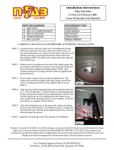
CARTON CONTENTS - PARTS
2
1
9
3
4
5
6
12
13
11
7
10
8
REF QTY PART NO DESCRIPTION
1 1 2-132BL3 Front Trailer Frame
2 1 2-133BL3 Rear Trailer Frame
3 1 2-134BL3 Tailgate
4 2 2-135BL3 Axle Mount Plate
5 1 2-136BL3 Axle Tube
6 2 2-137BL3 Axle Spindle
7 1 2-138BL3 Rear Tongue Tube
REF QTY PART NO DESCRIPTION
8 4 2-139OR1 Side Containment Rack
9 1 2-140OR1 Front Containment Rack
10 1 2-141BL3 Latch Tube Assembly
11 1 2-142BL3 Connector Pocket
12 1 2-143BL3 Front Tongue Tube
13 2 2-144 Trailer Wheel

4
A
B
J
P
K L M
N
O
C
E
D
F
G H I
SHOWN FULL SIZE
CARTON CONTENTS - HARDWARE
REF QTY PART NO DESCRIPTION
A 2 2-145 Washer, M20
B 7 2-146 Washer, M8
C 16 2-147 Washer, M6
D 2 2-148 Castle Nut, M20 x 1.5
E 5 2-149 Nut, M8 x 1.25
F 14 2-150 Nut, M6 x 1.0
G 2 2-151 Bolt, M8 x 1.25 x 100
H 1 2-152 Bolt, M8 x 1.25 x 70
REF QTY PART NO DESCRIPTION
I 2 2-153 Bolt, M8 x 1.25 x 60
J 2 2-154 Bolt, M6 x 1.25 x 65
K 6 2-155 Bolt, M6 x 1.25 x 50
L 2 2-156 Bolt, M6 x 1.25 x 45
M 4 2-157 Bolt, M6 x 1.25 x 40
N 2 2-158 Cotter Pin
O 1 2-159 Clevis Pin
P 1 714-0117 Hair Cotter Pin

5
TOOLS REQUIRED FOR ASSEMBLY
(2) 10 mm Wrenches
(2) 13 mm Wrenches
(1) 20 mm Socket with Ratchet and Extension
(1) Needle Nose Pliers
(1) Grease Gun
Lay out and identify the parts and hardware using the
illustrations on page 3 and page 4.
IMPORTANT ASSEMBLY TIPS
Do not tighten any nut and bolt combinations completely
until all parts are assembled together! Finger tighten plus
one turn of a wrench only. This will temporarily hold the
lock nut on the bolt while helping alignment of all parts.
After all parts are assembled together, all nut and bolt
combinations must be completely tightened.
Do initial assembly steps with the trailer frame parts
oriented upside down. This will aid in the assembly.
ASSEMBLE THE TRAILER FRAME
STEP 1: (SEE FIGURE 1)
• Ensure the front trailer frame (1) and rear trailer frame
(2) are upside down.
• Secure the sides of the front trailer frame (1) to the
sides of the rear trailer frame (2) using two M6x50 mm
bolts (K), M6 steel washers (C), and M6 locknuts (F).
• Secure the bottom of the front trailer frame (1) to
the bottom of the rear trailer frame (2) using two
M6x65 mm bolts (J), M6 steel washers (C), and M6
locknuts(F).
K
J
C
C
2
1
F
FIGURE 1
ATTACH THE AXLE MOUNTING PLATES
STEP 2: (SEE FIGURE 2)
• With the trailer assembly in the upside down position,
attach the top of the two axle mounting plates (4)
to the trailer frame assembly with four M6x40 mm
bolts(M), M6 steel washers (C), and M6 locknuts (F).
• Secure the bottoms of the two axle mounting plates (4)
using four M6x50 mm bolts (K), M6 steel washers (C),
and M6 locknuts (F).
K
C
4
K
M
M
F
FIGURE 2
ASSEMBLE THE HITCH
STEP 3: (SEE FIGURE 3)
• Insert the rear tongue tube (7) into the "u-bracket"
on the axle tube (5) and secure with one M8x70 mm
bolt(H), M8 steel washer (B), and M8 locknut (E).
• Secure the latch tube assembly (10) to the top of the
rear tongue tube (7) with two M8x100 mm bolts (G),
M8 steel washers (B), and M8 locknuts (E).
• Insert the latch tube assembly (10) and the front
tongue tube (12) into the connector pocket (11)
and secure with two M8x60 mm bolts (I), M8 steel
washers(B), and M8 locknuts (E).
H
E
E
G
12
11
10
7
5
B
I
B
B
FIGURE 3
ASSEMBLY INSTRUCTIONS

6
ATTACH THE TONGUE ASSEMBLY
STEP 4: (SEE FIGURE 4)
• Ensure the frame assembly is upside down.
• Attach the tongue assembly to the frame assembly
by inserting the short end of the two axle spindles (6)
through the axle mounting plates (4) and threading
into the axle tube (5). Thread axle spindles until snug
and then loosen until holes in the axle tube and
spindles are aligned. Secure the two axle spindles
to the axle tube using two M6x45 mm bolts (L) and
M6locknuts(F).
6
6
4
4
F
L
5
FIGURE 4
ATTACH THE WHEELS
STEP 5: (SEE FIGURE 5)
• Turn the cart assembly right-side up.
• Slide the two wheels (13) onto the axle spindles (6)
with grease ttings and air valves facing outward.
Secure with two 20 mm castle nuts (D) and 20 mm
steel washers (A). Tighten the castle nuts until snug
and then back off slightly to allow free movement of the
wheels and cotter pin (N) alignment.
• Insert the two cotter pins (N) through the axle spindles
(6) and castle nuts (D) so that the head of each cotter
pin is seated in the corresponding castle nut. Using a
pair of pliers, bend the prongs of the two cotter pins
around the other side of the castle nuts so that the
cotter pin cannot fall out.
• You must now tighten all nut and bolt assemblies.
Be sure not to over tighten or crush tubing when
tightening.
• Grease both wheels with a grease gun and
multipurpose bearing grease. Check the grease level
frequently to prevent bearings from excessive wear or
failure.
IMPORTANT: Make sure the tire pressure does
not exceed the maximum rating written on the tire.
Recommended operating pressure is 24 psi.
13
6
N
A
D
FIGURE 5
ASSEMBLE THE CONTAINMENT RACKS
STEP 6: (SEE FIGURE 6)
• Slide the removable tailgate (3) into the channels
on the rear trailer frame (2). Slide the four side
containment racks (8) and the one front containment
rack (9) into the corresponding tubes on the trailer
frame assembly.
8
9
3
2
FIGURE 6

7
ASSEMBLE THE CART TO YOUR VEHICLE
STEP 7: (SEE FIGURE 7)
• Use the clevis pin (O) and hair cotter pin (P) to attach
the cart to your vehicle.
P
O
FIGURE 7
OPERATION
CAUTION: Failure to obey the following
cautions could result in personal injury
or product damage:
When using this cart, ensure that you ALWAYS:
• Be sure the cart is securely attached to your ATV hitch.
• Check tires for correct air pressure before each use.
• Inspect before each and every use to be sure there
is no product damage or loose/missing bolts and
hardware.
• Have wheel bearings properly greased to keep
bearings from seizing.
When using this cart, ensure that you NEVER:
• Use excessive speeds while towing the cart.
• Exceed the maximum load capacity of 1250 Ib.
• Allow people or animals to ride in the cart.
• Use on hilly terrain.
• Use a damaged product.
• Use when intoxicated or using over-the-counter
medication or prescription drugs.
• Use on rocky or obstacle-ridden terrain.
• Use carelessly -- Think Safety!
MAINTENANCE
• Always clean the cart after each use.
• Check periodically for loose bolts.
• Check the grease level of the wheels frequently to
prevent bearings from excessive wear or failure.
• After extended periods of non-use, check the psi level
of the wheels. Maximum psi is 24.
WARRANTY

8
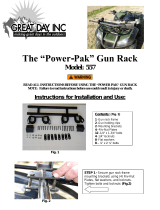
REPAIR PARTS FOR 45-0554 CART
9
8
1
27
14
13
6
19
25
21
5
7
10
11
15
18
12
20
22
17
3
2
23
24
16
4
24
29
28
26

9
REF QTY PART NO DESCRIPTION
1 1 2-132BL3 Front Trailer Frame
2 1 2-133BL3 Rear Trailer Frame
3 1 2-134BL3 Tailgate
4 2 2-135BL3 Axle Mount Plate
5 1 2-136BL3 Axle Tube
6 2 2-137BL3 Axle Spindle
7 1 2-138BL3 Rear Tongue Tube
8 4 2-139OR1 Side Containment Rack
9 1 2-140OR1 Front Containment Rack
10 1 2-141BL3 Latch Tube Assembly
11 1 2-142BL3 Connector Pocket
12 1 2-143BL3 Front Tongue Tube
13 2 2-144 Trailer Wheel
14 2 2-145 Washer, M20
15 7 2-146 Washer, M8
REF QTY PART NO DESCRIPTION
16 16 2-147 Washer, M6
17 2 2-148 Castle Nut, M20 x 1.5
18 5 2-149 Nut, M8 x 1.25
19 14 2-150 Nut, M6 x 1.0
20 2 2-151 Bolt, M8 x 1.25 x 100
21 1 2-152 Bolt, M8 x 1.25 x 70
22 2 2-153 Bolt, M8 x 1.25 x 60
23 2 2-154 Bolt, M6 x 1.25 x 65
24 6 2-155 Bolt, M6 x 1.25 x 50
25 2 2-156 Bolt, M6 x 1.25 x 45
26 4 2-157 Bolt, M6 x 1.25 x 40
27 2 2-158 Cotter Pin
28 1 2-159 Clevis Pin
29 1 714-0117 Hair Cotter Pin
— 1 3-80 Owners Manual
REPAIR PARTS FOR 45-0554 CART

the fastest way to purchase parts
www.speedepart.com
© 2021 Agri-Fab, Inc.
REPAIR PARTS
Agri-Fab, Inc.
809 South Hamilton
Sullivan, IL. 61951
217-728-8388
www.agri-fab.com
This document (or manual) is protected under the U.S. Copyright Laws and the copyright laws of foreign countries,
pursuant to the Universal Copyright Convention and the Berne convention. No part of this document may be reproduced
or transmitted in any form or by any means, electronic or mechanical, including photocopying or recording, or by any
information storage or retrieval system, without the express written permission of Agri-Fab, Inc. Unauthorized uses and/or
reproductions of this manual will subject such unauthorized user to civil and criminal penalties as provided by the United
States Copyright Laws.
/