
Advance Technologies; Automate the World.
Manual Rev. 2.00
Revision Date: November 7, 2012
Part No: 50-15083-1000
cPCI-6620 Series
6U CompactPCI Processor Blade
with 2nd Generation Intel
®
Core™ i7/Celeron
®
User’s Manual

Revision History
Revision Release Date Description of Change(s)
2.00 2012/11/7 Initial release

Preface iii
cPCI-6620
Preface
Copyright 2012 ADLINK Technology Inc.
This document contains proprietary information protected by copy-
right. All rights are reserved. No part of this manual may be repro-
duced by any mechanical, electronic, or other means in any form
without prior written permission of the manufacturer.
Disclaimer
The information in this document is subject to change without prior
notice in order to improve reliability, design, and function and does
not represent a commitment on the part of the manufacturer.
In no event will the manufacturer be liable for direct, indirect, spe-
cial, incidental, or consequential damages arising out of the use or
inability to use the product or documentation, even if advised of
the possibility of such damages.
Environmental Responsibility
ADLINK is committed to fulfill its social responsibility to global
environmental preservation through compliance with the Euro-
pean Union's Restriction of Hazardous Substances (RoHS) direc-
tive and Waste Electrical and Electronic Equipment (WEEE)
directive. Environmental protection is a top priority for ADLINK.
We have enforced measures to ensure that our products, manu-
facturing processes, components, and raw materials have as little
impact on the environment as possible. When products are at their
end of life, our customers are encouraged to dispose of them in
accordance with the product disposal and/or recovery programs
prescribed by their nation or company.
Trademarks
Product names mentioned herein are used for identification pur-
poses only and may be trademarks and/or registered trademarks
of their respective companies.

iv Preface
Using this Manual
Audience and Scope
The cPCI-6620 User’s Manual is intended for hardware
technicians and systems operators with knowledge of installing,
configuring and operating industrial grade CompactPCI modules.
Manual Organization
This manual is organized as follows:
Chapter 1, Overview: Introduces the cPCI-6620, its features,
block diagrams, and package contents.
Chapter 2, Specifications: Presents detailed specification
information, and power consumption.
Chapter 3, Functional Description: Describes the cPCI-6620’s
main functions.
Chapter 4, Board Interfaces: Describes the cPCI-6620 board
interfaces, pin definitions, and jumper settings.
Chapter 5, Getting Started: Describes the installation instructions
of the cPCI-6620.
Chapter 6, Drivers & Utilities: Describes the driver installation
procedures.
Chapter 7, BIOS Setup Utility: Describes the AMI EFI BIOS
setup utility.
Important Safety Instructions: Presents safety instructions all
users must follow for the proper setup, installation and usage of
equipment and/or software.
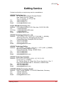
Getting Service: Contact information for ADLINK’s worldwide
offices.

Preface v
cPCI-6620
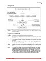
Conventions
Take note of the following conventions used throughout this
manual to make sure that users perform certain tasks and
instructions properly.
NOTE:
NOTE:
Additional information, aids, and tips that help users perform
tasks.
CAUTION:
Information to prevent minor physical injury, component dam-
age, data loss, and/or program corruption when trying to com-
plete a task.
WARNING:
Information to prevent serious physical injury, component
damage, data loss, and/or program corruption when trying to
complete a specific task.

vi Preface
This page intentionally left blank.

Table of Contents vii
cPCI-6620
Table of Contents
Revision History...................................................................... ii
Preface.................................................................................... iii
List of Tables.......................................................................... ix
List of Figures........................................................................ xi
1 Overview ............................................................................. 1
1.1 Introduction.......................................................................... 1
1.2 Features............................................................................... 2
1.3 Block Diagram ..................................................................... 2
1.4 Product List.......................................................................... 3
1.5 Package Contents ............................................................... 4
2 Specifications..................................................................... 5
2.1 cPCI-6620 Specifications..................................................... 5
2.2 I/O Connectivity ................................................................... 7
2.3 Power Requirements........................................................... 8
3 Functional Description .................................................... 11
3.1 Processors......................................................................... 11
3.2 Platform Controller Hub ..................................................... 13
3.3 Intel® Turbo Boost Technology......................................... 14
3.4 Intel® Hyper-Threading Technology.................................. 14
3.5 Battery ............................................................................... 15
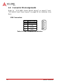
4 Board Interfaces............................................................... 17
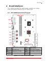
4.1 cPCI-6620 Series Board Layout........................................ 17
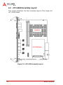
4.2 cPCI-6620 Assembly Layout ............................................. 18
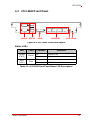
4.3 cPCI-6620 Front Panel...................................................... 19
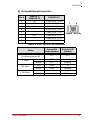
4.4 Connector Pin Assignments .............................................. 20
4.5 Switches ............................................................................ 26

viii Table of Contents
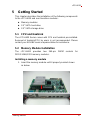
5 Getting Started.................................................................. 27
5.1 CPU and Heatsink ............................................................. 27
5.2 Memory Module Installation............................................... 27
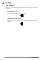
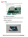
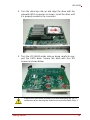
5.3 SATA Drive Installation...................................................... 28
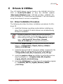
6 Drivers & Utilities.............................................................. 31
6.1 Driver Installation Procedure.............................................. 31
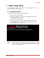
7 BIOS Setup Utility............................................................. 37
7.1 Starting the BIOS............................................................... 37
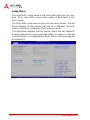
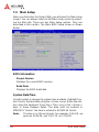
7.2 Main Setup......................................................................... 40
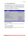
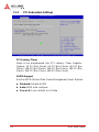
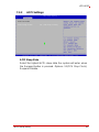
7.3 Advanced BIOS Setup....................................................... 41
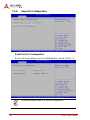
7.4 Chipset Configuration ........................................................ 54
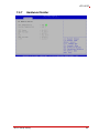
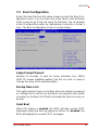
7.5 Boot Configuration............................................................. 61
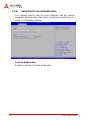
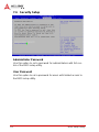
7.6 Security Setup.................................................................... 62
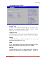
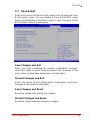
7.7 Save & Exit ........................................................................ 63
Important Safety Instructions............................................... 65
Getting Service...................................................................... 67

List of Tables ix
cPCI-6620
List of Tables
Table 2-1: cPCI-6620 Specifications ......................................... 6
Table 2-2: cPCI-6620 I/O Connectivity ...................................... 7
Table 2-3: CompactPCI Input Voltage Characteristics .............. 8
Table 4-1: cPCI-6620 Front Panel Status LED Descriptions ... 19
Table 4-2: USB Connector Pin Definition ................................ 20
Table 4-3: GbE Connector Pin Definitions ............................... 21
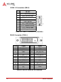
Table 4-4: COM1~2 Connector Pin Definition ......................... 22
Table 4-5: DVI-D Connector Pin Definition .............................. 22
Table 4-6: SATA Direct Connector Pin Definition .................... 23
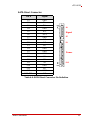
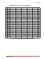
Table 4-7: CompactPCI J1 Connector Pin Definition ............... 24
Table 4-8: CompactPCI J2 Connector Pin Definition ............... 25

xList of Tables
This page intentionally left blank.

List of Figures xi
cPCI-6210
List of Figures
Figure 1-1: cPCI-6620 Series Block Diagram.............................. 2
Figure 4-1: cPCI-6620 Series Board Layout.............................. 17
Figure 4-2: cPCI-6620 Assembly Layout................................... 18
Figure 4-3: cPCI-6620 Front Panel Layout................................ 19

xii List of Figures
This page intentionally left blank.

Overview 1
cPCI-6620
1Overview
1.1 Introduction
The cPCI-6620 is a highly integrated 6U CompactPCI blade in
dual slot width (8HP) form factor. Its design is based on the 2nd
Generation Intel® Core™ i7 and Celeron® processors in
FCBGA1023 package with Mobile Intel® HM65 Express Chipset.
The cPCI-6620 is a value 6U CompactPCI blade that offers inte-
grated graphics, I/O bandwidth, asset management capabilities,
data transfer speed and reliability.
The cPCI-6620 supports dual-channel unbuffered
DDR3-1066/1333 memory up to a maximum capacity of 16GB.
Graphics is integrated in the processor and output is provided
through one DVI-D port on the front panel.
The cPCI-6620 offers versatile I/O such as four Gigabit Ethernet
ports, two DB-9 COM ports, four Type-A USB 2.0 ports, and one
DVI-D port on the front panel. The blade supports a 32-bit/33MHz
CompactPCI interface and integrates a Super I/O IT8718F to mon-
itor CPU and system temperature, DC voltages and provide a
watchdog timer.
Storage features of the cPCI-6620 include a SATA 6 Gb/s direct
connector interface with mounting space for a 2.5" HDD/SSD.

2Overview
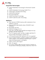
1.2 Features
X Supports dual-core Intel® Core™ i7-2655LE processor
X Up to 16GB DDR3-1333 memory in two DIMMs
X Supports real-time RTX on Windows
X Four Gigabit Ethernet egress ports
X 5V power input only
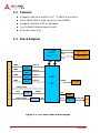
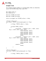
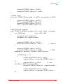
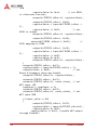
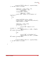
1.3 Block Diagram
Figure 1-1: cPCI-6620 Series Block Diagram
F
R
O
N
T
P
A
N
E
L
USB 0/1/2/3
DMI
COM1
,
COM2
PCIe x1
LAN3
2
nd
Gen
Intel®
Core™ i7
J1/J2
Intel
82574L
LAN1
SATA0
LPC
Intel
82574L
2.5” HDD
BIOS
SPI
240pin DIMM
CHB
CHA
IT8718F
TI XIO2001IZ
PCIe x1
FDI
PCIe x1
Intel
82574L
LAN2
DVI
PCIe x1
HM65
PCH
240pin DIMM
Intel
82574L
PCIe x1 LAN4
DDR3 1066/1333
PCI 32b/33M
CH7318C
TMDS

Overview 3
cPCI-6620
1.4 Product List
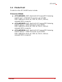
Products in the cPCI-6620 Series include:
Processor Blade
X cPCI-6620/655L: 8HP (dual slot) 6U CompactPCI featuring
Intel® Core™ i7-2655LE Processor; up to 16GB
DDR-1066/1333; GbE x4, COM x2, DVI-D, USB x4,
onboard SATA connector
X cPCI-6620/847E: 8HP (dual slot) 6U CompactPCI featuring
Intel® Celeron™ 847E processor; up to 16GB
DDR-1066/1333; GbE x4, COM x2, DVI-D, USB x4,
onboard SATA connector
X cPCI-6620/810E: 8HP (dual slot) 6U CompactPCI featuring
Intel® Celeron™ 810E Processor; up to 16GB
DDR-1066/1333; GbE x4, COM x2, DVI-D, USB x4,
onboard SATA connector

4Overview
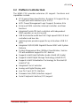
1.5 Package Contents
The cPCI-6620 is packaged with the components listed below. If
any of the items in the contents list are missing or damaged, retain
the shipping carton and packing material and contact the dealer
for inspection. Please obtain authorization before returning any
product to ADLINK. The packing contents of non-standard config-
urations may vary depending on customer requests.
Processor Blade
X The cPCI-6620 Series Processor Blade
Z CPU and memory specifications will differ depending on
options selected
Z Thermal module is assembled onboard
X 2.5" SATA drive accessory pack
X ADLINK All-in-One DVD
X User's manual
NOTE:
NOTE:
The contents of non-standard cPCI-6620 Series configurations
may vary depending on customer requests.
CAUTION:
This product must be protected from static discharge and phys-
ical shock. Never remove any of the components except at a
static-free workstation. Use the anti-static bag shipped with the
product when putting the board on a surface. Wear an
anti-static wrist strap properly grounded on one of the system's
ESD ground jacks when installing or servicing system compo-
nents.

Specifications 5
cPCI-6620
2 Specifications
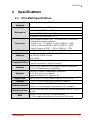
2.1 cPCI-6620 Specifications
CompactPCI
Standard
PICMG® 2.0 CompactPCI® Rev. 3.0
Mechanical
Standard 6U CompactPCI®
Board size: 233.23 mm x 160mm
Dual slot (8HP, 40.64 mm) width
CompactPCI® connectors J1, J2
Processor
2nd Generation Intel® Core™ processor in FCBGA1023
package with passive heatsink
• Intel® Core™ i7-2655LE, 2.2GHz, 4MB LLC, 25W
• Intel® Celeron® B810E, 1.6GHz, 2MB LLC, 35W
• Intel® Celeron® 847E, 1.1GHz, 2MB LLC, 17W
Chipset Intel® HM65 Platform Controller Hub (PCH)
Memory
Dual channel unbuffered DDR3-1066/1333 memory
Two 240-pin DIMM sockets
Up to 16GB
CompactPCI Bus
PCI 32-bit/33MHz; 3.3V, 5V universal V(I/O)
Supports operation in system slot only
Ethernet
Four PCIe x1 Intel® 82574L Gigabit Ethernet controllers
Four RJ-45 LAN ports on front panel
Graphics
Intel® HD Graphics integrated in processor
One DVI-D port on front panel
Supports DirectX 10.1, OpenGL 3.0
Serial Ports Two DB-9 RS-232 ports from Super I/O ITE IT8718F
Storage One 2.5" SATA 6 Gb/s direct connector onboard
Hardware Monitor
Integrated in Super I/O IT8718F
Monitors CPU and system temperature, DC voltages
Watchdog Timer
System reset and NMI, with programmable interval, 1-65535
sec/min
BIOS
AMI® EFI BIOS 64Mbit SPI flash memory
PXE Boot agent supported on front panel GbE ports

6 Specifications
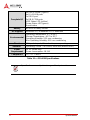
Table 2-1: cPCI-6620 Specifications
Faceplate I/O
4x USB 2.0 ports (Type-A)
4x RJ-45 LAN ports
1x DVI-D port
2x DB-9 COM ports
HDD Status LED (yellow)
Power Status LED (green)
Reset button
Battery BR2032 in battery socket
OS Support Windows XP/7 Embedded + RTX extension
Environmental
Operating Temperature: 0°C to 60°C
Storage Temperature: -40°C to 85°C
Operating Humidity: 95% non-condensing
Non-Operating Humidity: 95% non-condensing
Shock 15G peak-to-peak, 11ms duration, non-operating
Vibration
4
Operating: 2Grms. 5 to 500Hz, each axis (without HDD)
Power
Requirement
5V DC power only
Power consumption: 18.5 W
Compliance CE, FCC Class A
NOTE:
NOTE:
Specifications are subject to change without prior notice.

Specifications 7
cPCI-6620
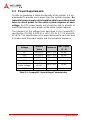
2.2 I/O Connectivity
cPCI-6620 Processor Blade
Table 2-2: cPCI-6620 I/O Connectivity
Notes:
1. One 22-pin direct connector for 2.5" SATA drive.
2. Power (green), Hard Disk (yellow)
Function Faceplate Board
COM (RS-232) Y x2 —
LAN Y x4 —
USB 2.0 Y x4 —
DVI-D Y —
SATA
Y
1
LEDs
2
Y x2 —
Reset Button Y —
Clear CMOS Button — Y

8 Specifications
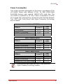
2.3 Power Requirements
In order to guarantee a stable functionality of the system, it is rec-
ommended to provide more power than the system requires. An
industrial power supply unit should be able to provide at least
twice as much power as the entire system requires of each
voltage. An ATX power supply unit should be able to provide at
least three times as much power as the entire system requires.
The tolerance of the voltage lines described in the CompactPCI
specification (PICMG 2.0 R3.0) is +5%/ -3% for 5, 3.3 V and ±5%
for ±12V. This specification is for power delivered to each slot and
it includes both the power supply and the backplane tolerance.
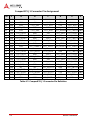
Table 2-3: CompactPCI Input Voltage Characteristics
Voltage
Nominal
Value
Tolerance
Max. Ripple
(P - P)
5V +5.0 VDC +5% / -3% 50 mV
3.3V +3.3 VDC +5% / -3% 50 mV
+12V +12 VDC +5% / -5% 240 mV
-12V -12 VDC +5% / -5% 240 mV
V I/O (PCI I/O
Buffer Voltage)
+3.3 VDC or
+5 VDC
+5% / -3% 50 mV
GND
Page is loading ...
Page is loading ...
Page is loading ...
Page is loading ...
Page is loading ...
Page is loading ...
Page is loading ...
Page is loading ...
Page is loading ...
Page is loading ...
Page is loading ...
Page is loading ...
Page is loading ...
Page is loading ...
Page is loading ...
Page is loading ...
Page is loading ...
Page is loading ...
Page is loading ...
Page is loading ...
Page is loading ...
Page is loading ...
Page is loading ...
Page is loading ...
Page is loading ...
Page is loading ...
Page is loading ...
Page is loading ...
Page is loading ...
Page is loading ...
Page is loading ...
Page is loading ...
Page is loading ...
Page is loading ...
Page is loading ...
Page is loading ...
Page is loading ...
Page is loading ...
Page is loading ...
Page is loading ...
Page is loading ...
Page is loading ...
Page is loading ...
Page is loading ...
Page is loading ...
Page is loading ...
Page is loading ...
Page is loading ...
Page is loading ...
Page is loading ...
Page is loading ...
Page is loading ...
Page is loading ...
Page is loading ...
Page is loading ...
Page is loading ...
Page is loading ...
Page is loading ...
Page is loading ...
Page is loading ...
-
 1
1
-
 2
2
-
 3
3
-
 4
4
-
 5
5
-
 6
6
-
 7
7
-
 8
8
-
 9
9
-
 10
10
-
 11
11
-
 12
12
-
 13
13
-
 14
14
-
 15
15
-
 16
16
-
 17
17
-
 18
18
-
 19
19
-
 20
20
-
 21
21
-
 22
22
-
 23
23
-
 24
24
-
 25
25
-
 26
26
-
 27
27
-
 28
28
-
 29
29
-
 30
30
-
 31
31
-
 32
32
-
 33
33
-
 34
34
-
 35
35
-
 36
36
-
 37
37
-
 38
38
-
 39
39
-
 40
40
-
 41
41
-
 42
42
-
 43
43
-
 44
44
-
 45
45
-
 46
46
-
 47
47
-
 48
48
-
 49
49
-
 50
50
-
 51
51
-
 52
52
-
 53
53
-
 54
54
-
 55
55
-
 56
56
-
 57
57
-
 58
58
-
 59
59
-
 60
60
-
 61
61
-
 62
62
-
 63
63
-
 64
64
-
 65
65
-
 66
66
-
 67
67
-
 68
68
-
 69
69
-
 70
70
-
 71
71
-
 72
72
-
 73
73
-
 74
74
-
 75
75
-
 76
76
-
 77
77
-
 78
78
-
 79
79
-
 80
80


ADLINK Technology cPCI-6620/847E User manual
- Type
- User manual
- This manual is also suitable for
Ask a question and I''ll find the answer in the document
Finding information in a document is now easier with AI
Related papers
-
ADLINK Technology SP-15W03 Series User manual
-
-
-
-
-
-
-
-
ADLINK Technology cPCI-6930 User manual
-
Other documents
-
Intel BX50887430 User manual
-
-
ESD CPCI-HD/2 Owner's manual
-
-
-
-
Intermec PEN*KEY 6620 Technical Reference
-
Connect Tech JB0 User manual
-
AOpen Digital Engine DE965 Assembly Manual
-