Installation Guide
2
AT-OME-PS62
ENTER
1
4
2 3
5 6
MENU
PRESENTATION SWITCHER
OMEGA
TM
PWR: 100-240VAC 50/60Hz
RX TX
RS-232 IP MODE
RESET
12121 53 4 2
LAN
6
USB-C IN
HOST USBHDBaseT IN HDMI IN OUTPUTUSB HUB
MIC
48V
LINE
LINE IN
MIC
AUDIO OUT
RL
1
RL
2
RL
2
AUDIO IN
RL
1
AT-OME-PS62
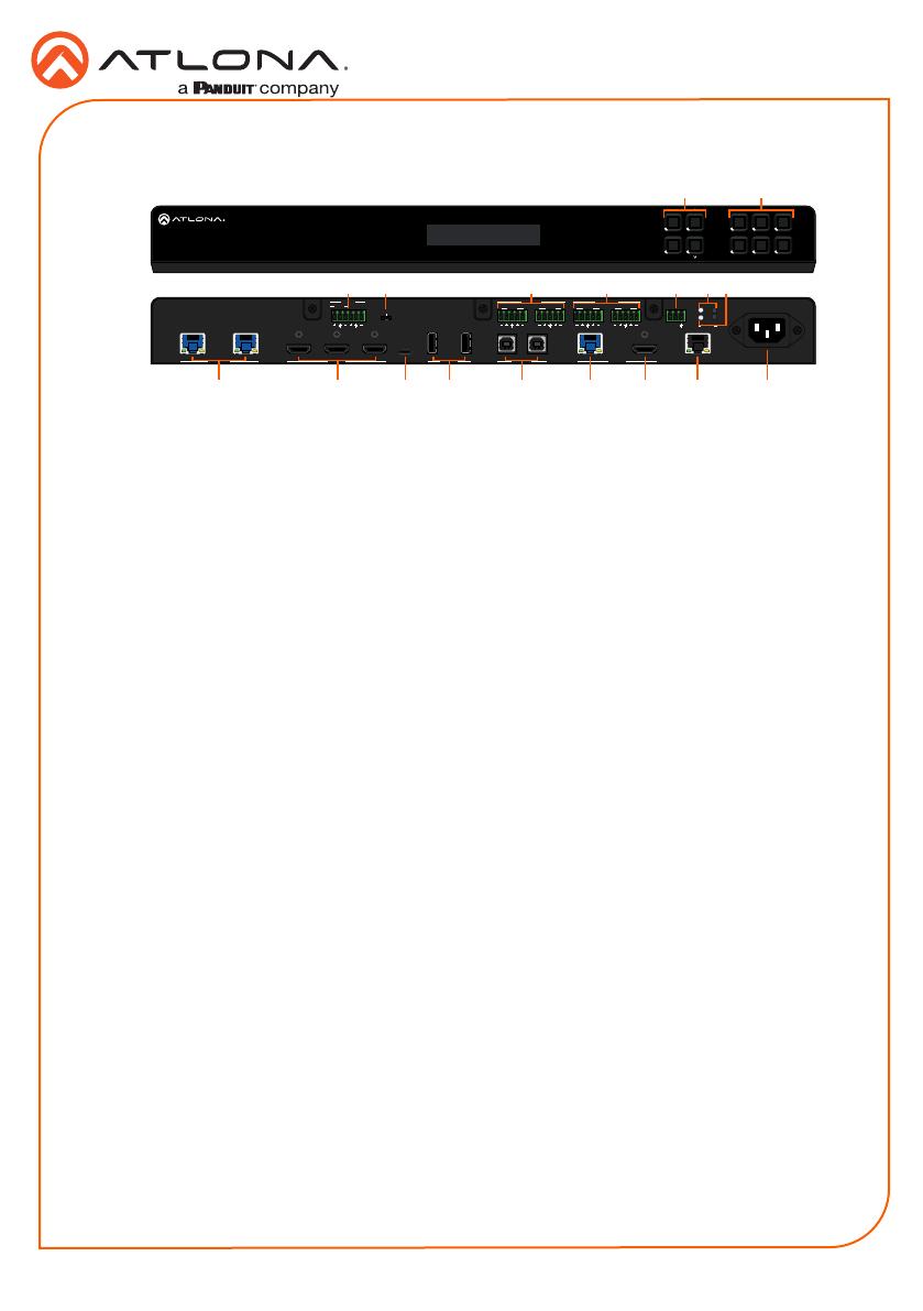
Panel Descriptions
10
14
131112 1715 16 18
1 2
53 7 8 94 6
1 Function Buttons
MENU - Access the front panel menu or
use as a back button within the menu. The
menu can be used to route inputs, change
audio and EDID settings, and view device
information.
ENTER - Used for making selection within
the front panel OSD.
^ and - Use to navigate through the
front panel menu.
2 Number Buttons
Use for selection of inputs and outputs.
3 MIC/LINE input
Connect microphone or line input to this
port.
4 MIC/LINE dip switch
Use to switch between MIC, 48V, and line
input.
5 AUDIO IN
Connect 2CH audio sources to these
ports.
6 AUDIO OUT
Connect to an audio DSP, amplier, or
other audio distribution devices.
7 RS-232
Use for device or display control.
8 IP MODE LED and button
Press and hold the button for 5 seconds
until the LED blinks to switch the IP mode
between DHCP and Static IP modes. The
LED will blink 2 times for DHCP and 3
times for static IP.
9 RESET LED and button
Press and hold the button for 5 seconds
until the unit resets. The LED will blink as
the unit resets to factory default settings.
10 HDBaseT IN
Connect a compatible HDBaseT
transmitter to this port.
11 HDMI IN
Connect HDMI cables to these ports from
HDMI sources.
12 USB-C IN
Connect a USB-C source to this port.
13 USB HUB
Connect USB devices to these ports.
e.g. usb camera, mouse, etc.
14 HOST USB
Connect to a computer using a USB B to
USB A cable.
15 HDBaseT Output
Connect a CAT5e/6/6a/7 cable from this
port to an HDBaseT receiver.
16 HDMI Output
Connect an HDMI cable from here to an
HDMI display.
17 LAN
Connect an Ethernet cable to this port for
control of the unit or to pass Ethernet to a
local device.
18 100-240VAC 50/60Hz Power Port
Connect the included IEC cord from this
port to the wall for power.
^


