Page is loading ...

"
19
5
1
-
5
8
CESSNA
CSSna
ON YOUR TRAVELS,
STOP AT
CESSNA
SERVlCE STATIONS
FOR FAST,
EFFICIENT,
ECONOMICAL
SERVICE.
&£2d
CESSNA
AIRCRAFT COMPANY WICHITA,
KANSAS
Owner
o
Manual

This manual describes
the operation and
performance
of the
1957
and 1958
Cessna Model
182,
and
the
1958 Cessna
Sky-
lane. Equipment described as "Optional" denotes thatthe
subject equipment is optional on the
Model
182. Much
of
this
equipment is
standard
on the
1958
Cessna
Skylane.
Except
for minor
equipment changes, the
1957
and
1958
models are
identical
structurally
and operationally, and have the same
performance;
therefore,
this manual is
applícable for
both
years.
The
main difference between
a
1957
and 1958
model
is
the rudder trim system which
is
installed on the
1958
model only. The
1957 model
has
a rudder trim tab
which
is
also described
in
this
manual.
D139-13-CES-250-12/73

Ûong
raf uÎahons
. . .
-
You are now the
owner
of a truly
outstand-
ing airplane.
Your Cessna has been engineered
to
give
you the ultimate
in performance,
styling,
durability, flying
comfort,
and
economy
for both
business and
pleasure.
-
We share your
pride
as a Cessna
owner
and
have prepared this
Owner's
Manual as a guide
to acquaint you with
your
airplane and its fine
construction,
equipment, ease of operation and
its care.
-
Every fine
possession is worth
caring for,
and this is
especially
true of your Cessna. This
book is
dedicated to help you
operate
your
air-
plane
to get
the utmost flying
enjoyment and
service with a minimum of care.
i

PRINClPLE
DlMENSIONS
Illllli I
82
- -
/
25' L75"
ii

TABLE
OF
CONTENTS
Page
SECTION I
-
DESCRIPTION . .
1-1
SECTION II
-
OPERATING
CHECK LIST
2-1
SECTION III
-
OPERATING
DETAILS
3-1
SECTION IV
-
OPERATING
LIMITATIONS
4-1
SECTION
V
-
OPERATIONAL DATA
5-1
SECTION
VI
-
CARE
OF THE
AIRPLANE- 6-1
OWNER'S RESPONSIBILITIES
CROSS
COUNTRY
SERVICE
6-26
ALPHABETICAL
INDEX
A-1
iii

1
2
3
4
5 6
7
8
9
10 11
12
13
14 15
16
17
18
19 28
30 29
24
21
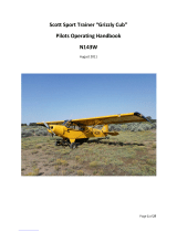
1. Headphone jack 12. Oil Pressure
Gage
22.
Optional
Radio Space
2. Azimuth
Indicator
(Opt. Equip
)
13.
Compass Card Holder
25.
Carburetor
Air Temperature
Gage
3.
Speed
Control
Indicator
(Opt.
Equip.)
14. Manifold Pressure
Gage
(Opt.
Equip.)
4. Clock
(Opt.
Equip.) 15. Oil
Temperature Gage 24.
Cylinder Head Temperature
Gage
5.
Turn
and Bank
Indicator (Opt. Equip.) 16.
Tachometer
(Opt.
Equip.)
6. Airspeed Indicator 17. Right Tank
Fuel
Quantity
Indicator 25.
Control
Panel (See 6gure 2)
7. Altimeter 18. Suction
Gage (Opt. Equip.) 26.
Fuel Strainer Drain Knob
8.
Directional
Gyro
(Opt. Equip.) 19. Glove
Compartment Door
Handle.
27. Optional Radio
9.
Rate-of-Climb
Indicator
(Opt.
Equip.)
20. Glove Compartment
Door 28. Parking
Brake
Handle
10. Gyro Horizon
(Opt.
Equip.) 21. Electrical
System
Control Panel
29.
Optional Instrument
Space
11.
Left Tank
Fuel Quantity
Indicator
(See ngure
5)
30.
Omni Indicator
(Opt. Equip.)
Figure 1. Instrument Panel

description
ONE OF
THE
FIRST STEPS
in obtaining
the
utmost performance,
service,
and
flying
enjoyment from your Cessna is to
familiarize
yourself
with
your
airplane's equipment,
systems, and controls. This
section will
tell
you
where
each
item
is
located,
how
it
operates
and
its
function.
ENGINE
FRICTION LOCKNUT
A
six-cylinder, Continental Model
0-470-L,
230 horsepower
engine
pow-
ers
your airplane. Compact,
depend-
able and
efficient,
the engine
incorpo-
rates
hydraulic
valve-lifters
which
silence valve operation. Built
by a
company whose name has
become a
byword
for
precision-built, perform-
ance-packed aircraft engines, the
Con-
tinental 230 horsepower engine means
top performance for your
airplane at
low
maintenance cost.
THROTTLE CONTROL
THROTTLE.
The throttle
(3,
figure 2) is
cen-
NOTE
trally located
on the
lower
half
of
the
Because
of the
constant
speed
instrument panel
and is
easily
identi-
propeller
mechanism,
standard
fled
by its
large,
round
knob.
Engine
equipment
on the
airplane,
power
can be
increased by
pushing
advancing the throttle
will
not
the throttle
in
toward
the instrument
increase
engine
rpm.
It will
panel
or
decreased by pulling the
con.
increase
the
manifold pressure.
trol
out.
To prevent the throttle
from
With
each
power
increase,
the
creeping, a
knurled, friction-type,
lock
constant
speed
propeller
auto-
nut is incorporated on the
control to matically takes a
larger
"bite",
secure
it
at
any
desired
setting. enabling
the
engine to run
at
I-1

DESCRIPTION
a
constant
speed at all times.
figure 2)
is located
to
the
left
of the
Engine rpm
can be
changed by
throttle.
The
push-pull
control
operates
adjusting the
propeller
control.
the carburetor air intake
butterfly
Refer
to "PROPELLER PITCH
valve which
proportions the hot and
CONTROL"
paragraph on
cold air
entering
the carburetor.
Pull-
page
1-5
for this procedure. ing
the control out provides
heated air
for the carburetor
while
pushing
the
control
all the way in
provides
only
cold
air
for
the carburetor.
LOCKING
LEVER
The
controL
has
a
center
button
locking device.
To move
the control.
press the lock button in with
the
thumb
and
hold
while
moving
the
control
to
the
desired
position.
Lock
the
control
by releasing
the
thumb
MIXTURE
CONTROL
pressure
on
the button.
Air
pulled into
the heater
muffs
MIXTURE CONTROL.
and
subsequently
into
the engine
does
not
pass through the
air filter. For
The mixture control
(7,
figure
2) is
·
this
reason,
when
taxiing
on
dirty,
the second
knob to the right
of
the
dusty, or sandy fields,
carburetor heat
throttle
in the
lower center
portion
of
should not be
used
until the engine is
the
instrument panel. A
locking
lever
cleared
prior to
take-off.
After
a
full
is
incorporated on
the control to
pre-
stop
landing
under
these
conditions,
vent
its
unintentional
use. To
lean
the
carburetor heat should be
returned
to
mixture,
it is
necessary
to
depress
the
full
cold in order
for the
air filter
to
locking
lever
while
pulling
the
mix-
become fully
effective again.
ture
control
knob
out.
This
operation
Carburetor
ice
can form on the
can
be
accomplished with
one hand
. .
.
by
using
the
thumb
to press the
lock-
ground with
the
engine idling.
There-
. -
fore,
just before
take-off,
when you
ing lever in and
the
index and middle
fingers to
pull
the
mixture control
run-up
the engine and check magnetos,
knob
out.
The
locking
lever
is
effec-
be sure to
put
the carburetor heat in
tive
only
in
the
leaning
operation.
the "ON" position after
the
magneto
Forward movement
of
the mixture
check.
Leave
it in this position
until
control is not affected by
the locking
just
before
you
open the throttle
for
lever. For detailed
operating
instruc
the
take-off
run. Then
move
carburet-
or heat to the
"COLD AIR" osition.
tions
on the use
of
the
mixture
con-
P
trol,
refer to Section III.
This
gives
maximum power
for the
take-off.
Watch
engine for
any
indi-
CARBURETOR AIR HEAT
CONTROL
cations
of
ice
(roughness or
a
drop
in
The
carburetor
air heat control
(1, manifold pressure) during
climb
and
1-2

DESCRIPTION
ALPHABETICALINDEX
Right Tank
Fuel
Quantity
indicator,
iv
Take-Off,
2-3, 3-2,
3-4
5 7
Rudder Control System,
6-10,
6-11
crosswind,
2-3
Ruger
Pedals,
1-13,
1-14
diagram,
5-2
Rudder
Tab,
6-12
minimum
run,
2-3
Rudder Trim
Control
Wheel,
1-14
normal,
2-3
obstacle
clearance,
2-3
'EM
soft
or
rough field,
2-3
k
-O
an3d3-Climb
Chart,
5-3
S
Throttle, 1-1,
1-3
Tie-Down
Procedure,
5-8
Tires,
6-2
m mpener,
6-3
Tu
pressurLnk3Indicator,
iv,
1-17
Speed
Control
Indicator, iv
Stabilizer
Control System,
6-12,
6-13
Stall
Warning
Indicator,
1-17
Stall Warning
Transmitter
Heater,
1-17
Staalling3-7peeds
Chart,
3-7
U
Figure
2.
control
Panet
Starter
Button,
1-4,
1-10
I
Carburetor Air
Heat
Control
5.
Propeller
Pitch
Control 8.
Cabin
Heat Knob
Starting Engine, 2-1,
3-1
Upholstery,
6-6
2.
Generator
Warning
Light
6.
Cigarette
Lighter
9.
Cabin Air
Knob
Steering,
6-10
Utility
Shelf,
1-23
3. Throttle
7.
Mixture
Control
10.
Ignition Switch
Stopping Engine,
3-3 4. Ash
Receiver
i1. Engine Primer
Storage, Airplane,
6-2
Suction
Gage, iv apply
full
carburetor
heat if carburetor heat,
engine oper2tion may become
Switch,
begins to
ice.
(No change
will be
no-
rough
due
to too
rich a
mixture.
dome
light,
1-21
-
ignition,
1-3
ticed in
the rpm
because
the constant
Therefore,
for
prolonged
cruising
instrument lights,
1-21
speed
propeller
will
automatically night,it
may be
necessary
to lean
the
Innding
light,
1-10
Vacuum
Source
Selector,
iv
compensate for this.)
mixture
whenever
full
carburetor
map light,
1-21
marker
beacon,
1-11
The
correct
way
to use carburetor
heat is
used.
master, 1-10,
1-11
heat is to first use full heat to
remove
v
tn light,
1-10
any
ice that is
forming.
By
trial and
IGNITION
SWITCH.
pitot
heater,
1-11
W
error,
determine the minimum amount
The
key-operated
ignition switch
radio,
1-10,
1-11
of heat required
to
prevent
the
ice (10,
figure
2) is located below and
starter,
1-4,
1-10
WWgmht nadnd Ground
Te2st,
2-2
from
forming; each time removing any
slightly to the
right of
the throttle.
Wheel Alignment,
6-3
ice that is formed
by applying
full
This
switch controls
the
dual-magneto
Wheels, Landing
Gear,
6-2
heat. On
each
subsequent
trial,
in-
ignition system.
The four switch
posi-
h
abi5n,
6-5
crease the amount
of
heat
applied
until tions
are
"OFF",
"
R",
"L and
T Wing
Adjustment,
6-18
no ice forms. On approach glide
just "BOTH". The left
magneto
Sres the
Wing Flap
Handle,
1-14,
1-15
before
reducing
power,
apply
full
car-
upper
spark
plugs on
the left bank of
Table
of Contents, m
Wing
Flap Settings,
1-15
-
Tachometer,
iv,
1-4
Wiring Diagram,
6-14,
6-15
buretor heat
and
leave in
this
posi-
engine cylinders and
the
lower spark
tion.
plugs
on the right bank while the
Carburetor heat is rarely
necessary
right
magneto fires
the remaining
or desirable during cruising
night. spark
plugs.
The engine should be
However,
if
cruising
nightconditions operated on both magnetos, because
demand the use of
full
carburetor
the dual ignition provides
a more

DESCRIPTION
ALPHABETICALINDEX
complete
burning
of the
fuel-air
mix-
that
the engine
be turned
over
L O
ture driving the pistons. The
"R"
and
while priming.
It may be
nec-
Landing,
2-5,
3-7
Oil
Dilution
System,
3-9
L"
positions are used for
checking
essary
to continue
priming
crosswind,
2.5
switch,
1-11
purposes only.
until the engine runs
smoothly.
diagram,
5.6
Oil Filler
Cap,
1-6
normal,
2-5 Oli
Level,
1-6
ENGINE PRIMER.
STARTER
BUTTON.
short
field,
2-5
Oil Pressure Gage, iv,
1-8
Landing
Gear, 1-15,
6-2
Oil Specification and
Grade,
1-8
The engine primer (11,
figure 2)
is
A
push-button
switch
(1, figure
5)
Landing
Lights,
1-20
Oil
System,
1-6
a
manual
pump
type
and
is
located
operates
the
electrical starter motor
Left Tank
Fuel
Quantity Indicator,
iv
schematic,
1-7
below
and
slightly
to
the
left of
the
. .
.
Let-down,
2-4,
3-3
Oil Temperature Gage,
iv,
1-8
.
and is located at the
left
side
of
the
in-
Lifting and
Jacking,
6-2
Omm
Indicator,
iv
throttle.
Regardless
of the outside air
Light
Operations
Authorized,
4-1
temperature, use of
the
primer is
nor-
strument panel
dome,
i-2i
optionalRadio space, iv
mally
required
for
starting the
engine.
TACHOMETER.
(*|*
or
ning, 1-io,
1-13
OxcyÃ
dSys m,
3-9
The
primer aids
starting by
supplying
A
recording
engine
tachometer (16,
landing,
1-2o
diagram,
a-il
an
initial
charge of
raw fuel to the
figure 1)
is mounted
above the
en-
map,
1-21
duration
chart,
3-12
navigation,
1-20 face
mask,
3-14
engine
cylinders-
gine
instrument
cluster on the
right
radio dial,
1-21 flow
indicator,
3-14
NOTE
side of
the
instrument panel.
The
Lighting
Eguipment,
1-20
operation,
3-10
Only
five
cylinders are
primed
tachometer indicates engine RPM and
a ra¢ce
sna 182,
i-2a
9pru
scoangn
c couplings,
a-i2
by
the
engine primer. The
right
records
engine operating hours.
Lower
Forward
Section of
Cabin,
1-14
regulator,
3-11
rear
cylinder
(No.
1) provides
MANIFOLD PRESSURE
GAGE.
Lubricartion, b167
schematic,
3-13
the
manifold pressure source
A
manifold pressure gage
(14,
fig-
connection
and is not primed. . .
.
ure
1) is
mounted
immediately to the
To
operate the primer, proceed
as
left of
the
tachometer and above
the
follows:
engine
instrument
cluster on
the
right
M
(1)
First,
unlock
the plunger
by
side of
the
instrument panel.
This
in-
Parking
Brake
Handle, iv,
1-16
turning
the knob
counter-
strument
indicates
the
pressure
of
the
Magnetic Compass,
1-18
Parking
Brake Operation,
1-16
-
Main
Landing Gear,
1-15
Pitot
Heater,
1-17
clockwise until the knob pops
fuel-air
mixture
entering the
engine
Maneuvers,
Pitot
-
Static System,
1-17
part
way
out-
cylinders and
is
calibrated in
inches
normal
category,
4-1
Pressure,
Tire,
6-3
(2) Slowly
pull the
plunger all
of mercury. By
observing
the manifold
Manifold Pressure
Gage, iv,
1-4
Primer, Engine,
1-3,
1-4
Map Light,
1-21
Principle Dimensions,
n
the
way
out and then
push the
pressure gage
and
adjusting the
pro-
Map
Pocket,
1-23
Propeller,
1-5,
6-7
plunger all the
way
in.
This
peller
and
throttle
controls, the
power
Marker
Beacon
Switch,
1-11
Propeller
Pitch Control,
1-3,
1-5
action
is
termed "one
stroke
out ut
of the en
ine
can be adjusted to
Master
Switch,
1-10,
1-11
Miscellaneous
Equipment,
1-22
of the
primer"-
any
power
setting
recommended in the
Mixture control
Knob,
1-2,
1-3
(3)
Normal weather
will require
operating
procedures of Section
II
or
Mooring
Your
Airplane,
6-1
one
or two strokes
of the
performance charts of Section V.
primer,
and very cold
(-20°
F)
weather
may require
three
or
CYLINDER
HEAD
TEMPERATURE
Radio
Dial
Light,
1-21
four
strokes.
GAGE.
(OPTIONAL
EQUIPMENT.)
Radio
Switch,
1-10,
1-11
(4)
Normally,
the
engine
is
start-
A
cylinder
head
temperature
gage
N
ns.c
,b
5a
ed
immediately
after the
prim-
(24, figure
1)
is mounted immediately
Navigation Lights,
1-20
Rear
Seat,
1-18
ing
operation.
In
very cold
below the
engine instrument
cluster
on
nasher,
1-20
Rheostat,
Instrument Lights,
1-21
weather
it is
recommended
the right side of
the
instrument
panel.
Nose
Gear,
1-15
Rheostat,
Radio Dial Light,
1-21
A-3
1-4

ALPHABETICAL
INDEX DESCRIPTION
E
Gyro Horizon,
iv
The
gage
is
calibrated in
degrees
stant speed
feature
enables your
en-
Ground
Service Plug,
1-12,
6-14
Fahrenheit
and
is
electrically
operated. gine to
deliver
uniform
horsepower
Electrical
System,
1-11
However,
its sole
source of power
is
for each
throttle
setting.
control panel,
iv,
1-10,
1-11
schematic,
1-12
a thermocouple mounted
under
the
PROPELLERPITCH
CONTROL.
wiring diagram,
6-14,
6-15
lower
spark
plug of
the
left
rear en
The control
knob
(5,
figure
2)
to
Ele a r
Control
System,
6-12
H
gine cylinder and thus the
instrument
the right
of
the
throttle controls the
before
starting,
2-1,
3-1
Headphone Jack, iv
requires no power from the
electrical
engine speed. With
the
control
full
comraa nn
t
i6ons,
4-2
Heating
System, 1-18,
1-19
system. By
observing
the
gage
read-
forward, the
propeller
is in high
rpm
operating
procedure,
3-1
ings and
adjusting
the power
setting
position. It is moved
through its
com-
primer, 1-3,
1-4
the pilot can keep the engine
temper-
plete range by
pressing in the control
starting,
2-1,
3-1
atures
within
operating
limitations
lock
button in the
center of the
knob
stoppmg,
3-3
warm-up,
2-2,
3-2
PROPELLER.
and
pulling
out
the control
knob
to
Exterior Inspection
Diagram,
1-24
A
constant speed
propeller
is
stand.
its full
out or low
rpm position. For
Ignition
Switch,
1-3
ard
equipment
on
your
airplane, and
sensitive
control,
the
control
knob
,at,°,ia,
¡,
provides
your
airplane
with
maximum
can
be
screwed in
or out by turning
azimuth,
iv
performance
at
take-off,
during
climb,
the knob
with
the thumb
lock
in
its
F
Ieft tank
fuel
quantity,
iv
and
while cruising.
normal
locking position.
g
a u I uantity,
iv
A
propeller with
low
blade
angles
In use,
the
recommended procedure
Flap
BCel
k
Adjustment,6
speed
control,
iv
gives the
best performance
for
take-off
is
to
move
the
control full forward
Flight Control
System, 1-13,
6-7
stall
warning,
1-17
and
climb,
while
a
propeller with
high
(high rpm)
for
taxiing
and
take-off.
Front
Seats,
1-18
Insp
n ann
1 r,
270
blade
angles is more adapted
to
high
After
take-off
and
climb,
screw out
FF
nea
i
ta n u
,
1-10
Inspection Service and inspection
Period,
6-19
speed and
high
altitude
flying.
propeller
control
to the desired
cruis-
Fuel
Quantity
Indicators, iv,
1-11
Instruments,
1-16
A fixed-pitch
propeller
ordinarily
is
ing
rpm. When
changing
rpm
settings
Fuel
Selector Valve,
1-8
'I t a n
,
-2
set
to
obtain
best
performance
while
during cruising flight, it is
recom-
SStrean
at
a n dn
ve 1-80
Instrument
Panel,
iv
the
airplane
is cruising, consequently
mended that
control be moved by
Fuel System,
1-8
Internal
Cabin Measurements,
6-2s
the
take-off
and
climb
characteristics
screwing
in or
out since a small
move-
schematic,
1-9
are not at their best. The constant
ment of the
control
will
cause
a
con-
el
Taankk
Sump
Drain
Plugs,
1-lo
speed
propeller will
permit
low blade
siderable
change in rpm.
angles
for
take-off
and
climb, thereby
Propeller
surging
(rpm
variation up
.!
giving optimum performance.
After
CONTROL
LOCK BUTTON
Jacking and Lifting,
6-2
the
airplane
has
reached
its
proper
altitude
and has
leveled
off,
the
pro-
G
peller
can be
changed
to
a
higher
Gage,
blade
angle
and thus provide
the
de-
carburetor air temperature, iv
sired
cruising
performance.
cylinder head temperature, iv,
1-4
The propeller is controlled
by
a
manifold
pressure,
iv,
1-4
.
oil
pressure,
iv,
1-8
Knob
governor
which
automatically changes
'
LOW RPM
HIGH RPM
oil
temperature,
iv,
1-8
cabin
air,
1-3
the
pitch
of
the propeller
to
counter-
suction,
iv
cabin
heat,
1-3
act
any
tendency
of the engine
to vary
Generator
Warning
Light, 1-3,
1-10,
1-13
carburetor
air heat
control, 1-2,
1-3
Glove Compartment,
iv,
1-23
fuel strainer
drain, iv,
1-lo
from
the
rpm
setting established
by
PROPELLER
PITCH CONTROL
Ground Handling,
6-1
mixture
control,
1-2,
1-3
the propeller
pitch control.
This
con-
A-2
I-5

DESCRIPTION
and down several times
before
engine
opening the
2ccess
door
on
the
left
ALPHABETICAL INDEX
smooths out and becomes steady) can side of
the engine
cowl
and
re2ding
be prevented
by smooth throttle
and
the oil
level
on the
dipstick, located
propeller
control
operation.
Do not
just
aft of the left rear
engine cylinder.
change
throttle and propeller
controlset-
The
dip
stick
incorporates
2
spring
cessnaService
Publications,
6-26
rings with
jerky
and rapid
motions.
lock which prevents
it
from
working
cigarette
Lighter,
1-3,
1-22
loose in
flight.
The dip
stick
can
be
Adjustable
Stabilizer
Control Wheel,
1-13
Circuit
Breakers, 1-11,
1-13
NOTE
removed
by rotating it
until
the spring
After
Landing,
2-5
Check
List,
2-1
If
the
engine power
and rpm
lock is
disengaged and
pulling
the dip
AAil
o
rran
de
6
-6
9
Clea
nn
um
surfaces,
6-5
are to be increased,
increase
the
stick
up
and
out.
When
replacing
the
Airplane
File,
6-18
battery,
6-4
propeller
control
first
and
then
dip
stick,
m2ke
sure
th2t
the spring
Airspeed Correction
Table,
5-1
carburetor air
filter,
6-6
the
throttle.
If
power and rpm
lock
is engaged.
AArspeedd
Ln
taa't
ns
4-1
enDgine compartment,
6-6
are
to be decreased,
reduce
the
To obtain
correct
oil
level
readings, Altimeter,
iv
tires,
6-3
throttle first
and
then
the
pro-
it is import2nt
that
the
engine
be
shut
Aluminum
Surfaces,
6-5
upholstery,
6-6
peller
control. In this
manner,
down
at least
5
to 10
minutes prior
to
g¡,
Sce ers,
1-3,
1-23
dh
d
65-5
excessive
cylinder
pressures
the oil check.
This
permits
the
engine
Assist
straps,
1-22
clearingthe Propeller,
3-1
will be
avoided.
oil to drain out
of the
engine oil
pas-
Azimuth Indicator,
iv
Climkb,
2-4 -62,
3-4
s2ges
into
the
oil sump
giving
a
more
coatHanger Hook,
1-23
OIL SYSTEM.
2ccur2te
oil
level
reading.
Cold Weather Operation,
3-8
Compass Card Holder, iv
The Continental
0-470-L
engine
has
NOTE control,
a
wet
sump
oil
system which
utilizes
Oil should
be
2dded
if
below
ad ta rle
stabilizer,
1-13
the engine
pan
as
an oil tank. Other
nine
quarts
and
should
be
full
saggage
compartment,
1-23
cabin heater,
1-3
major components of the
system
are
if
an extended
flight
is planned.
Battery,
6-4
carburetar air
heat,
1-2,
1-3
an
engine-driven
oil
pump
2nd an oil
.
.
.
Befav Entering
Airplane,
2-1
mixture,
1-2,
1-3
- The
oil
filler
cap
is
made accessible
Before Landin
2-4
panel,
1-3
cooler
mtegrally mounted on the
en-
s'
rk brak
by opening the access door
on
the
Befo;e
starting
Engine,
2-1,
3-1
pa ing e,
iv
gin
1
temperature is regulated
auto-
top of the engine
cowl. In repl2cing
Bef
te ke-Off,
2-3
propdell pitc1h,
14-3
.
. the
oil
filler
cap, make
sure that it
is
Brake Pedais,
1-16
wheels,
1-13
matically
in this
system
by a
thermo-
on
firmly
and
turned
clockwise
2s
far
Brake System,
1-16
Cross Country Service,
6-26
statically
controlled oil cooler. The Cruise,
3-2,
3-6
as it will
go
to prevent loss of oil thru
Cruisin
,
2-4
thermostat shuts
off the passage of
oil
9
. the
filler
neck.
cylinder
Head Temperature
Gage,
iv,
1-4
through
the
cooler whenever the oil
temperatures
are below
150°
F.
Ordi-
OIL SPECIFICATION AND GRADE.
narily, the
oil
cooler is
adequate to
Aviation grade
oil is recommended
keep
oil
temperatures well
within the
for your airplane and
should be
Cabin
Air Knob,
1-3
normal operating
range
as indicated
changed
every
25 hours of oper2tion
cabinAir
Temperature
Control
System,
1-18
D
by
the green
arc
on the
oil
tempera.
When
adding
or changing
oil, use
the
diagram,
1-19
ture
indicator.
gr2des
in
the
following
table:
cabin
Doors,
1-22
Dip
Stick,
1-6
Cabin
Heat
Knob,
1-3
Directional
Gyro,
iv
OIL LEVEL.
Average Outside
Recommended
cabinVentilators,
1-20
Dome
Light,
1-21
The oil c2pacity
of the
Continent21
Temperature OH
Grade
r Hec
2Co
ol,
1-2,
1-3
Drain Plu
,sump,
1-10
0-470-L
engine
is twelve quarts. The
Below
40°
F. SAE
30
carburetor
Air
Temperature
Gage,
iv
fuel
line,
1-10
quantity
can
be
checked
e2sily by
Above
40°
F. SAE
50
center
of
Gravity
Envelope,
4-3
oil
sump,
1-7
1-6
A--I

CARE
-
RESPONSIBILITIES
DESCRIPTION
THERMOSTAT
Sales a Seruite
PROPELLER
CONTROL
.
OIL
COOLER
PHOPELLER
(THERMOSTAT
OPEN)
CROSS
COUNTRY
SERVICE
'*,
THERMOSTAT
On
your cross
country
travels
make
it
a point to
stop at a
Cessna
*-
°1HLEC
service
station
for your service
requirements.
Your Dealer will be
PROPELLER
CLOSED)
glad to
supply
you with
a copy
of
a
current
service station list, or if
GOVERNOR
you wish,
you
may write to the Service Department, Cessna Aircraft
Company,
Wichita, Kansas,
asking
for it and
it
will
be
promptly
mailed
to you.
°'LLE
CAP
CESSNA SERVICE
PUBLICATIONS
I
a
The
Cessna
Aircraft
Company
publishes
and
revises,
as necessarv.
1.
O
OIL
OIL
PRESSURE
TEMPERATURE
Manuals,
Parts
Catalogs,
Service Letters
and Service News LetterS. GAGE
GAGE
This
material
goes to all
authorized
Cessna
Service
Stations so that
they
have the
latest
authoritative information
for
servicing
your
Cessna.
Your Cessna
Dealer
has
an owner
follow-up
system
to
notify
you
sue
on
when he
receives
information that applies
to
your Cessna.
In
addi
SCREEN
- -
-
OIL DIP
STICK
tion. if you wish, you
may
choose
to
receive
similar
not16cation
directly
from
the Cessna
Service
Department. A subscation card
DR
LIN
UG
is supplied
to
you in
your
airplane file for your
use,
should
you
FUEL
LINE
eboose to request
this service. Your
Cessna
Dealer will
be
glad to
',"°uMOOINL
OISLCRFIELENER
wpply you
with
details
concerning these follow-up
programs,
and
SOLENOID
stands
ready
through
his
Service
Department
to
supply you with
fast,
efficient,
low
cost service.
ENGINE
SUMP
ENGINE
PRESSURE
-
OIL
PUMP
RELIEF VALVE
ENGINE
OIL
Figure
3.
Oil
System Schematic
6-26
1--7

DESCRIPTION
CARE
-
RESPONSIBILITIES
NOTE
ing air
by a
filter screen located in the
During
oil
changes, remove and
air scoop. Proper
cleaning
and
servic-
clean oil filter screen
located
ing
of
this air filter is important to
Cabin (floor) Lengths:
.
. .
increase life
and maintain
top
efTi-
ynow
to
NOTE
on
the right side
of
the
engine
.
Measurements
are with
accessory
section.
ciency of
the
engine. The
filter
should .
. .
. . -
43 in
co-pilot seat,
rear
seat,
be
serviced every
25
hours
(during
- - -
21 in
and
baggage
compartment
OIL
TEMPERATURE GAGE-
regular oil
change)
or oftener
when
mh
o
abl
A capillary
type,
oil temperature
operating
in
dusty
conditions.
Under
27 in-
and
saving 40
lbs
on
emp-
gage (15, figure
1) is
mounted
within
extremely
dusty
conditions,
daily
the
engine instrument
cluster on
the maintenance
of
the
air filter
is
recom-
right
side of the
instrument
panel.
A
mended. Refer to
the
servicing
in-
green arc on
the
gage dial indicates
structions stamped
on
the
carburetor
'
the
normal operating range of
oil
air filter for the servicing
procedure
temperatures. Refer to
Section
IV
for
to
be used.
instrument markings.
OIL
PRESSURE
GAGE.
FUEL
SYSTEM.
An
oil
pressure gage
(12, figure
1)
Fuel
is
supplied
to the engine
from
is
mounted within
the engine
instru-
two
rubberized,
bladder-type
fuel
ment cluster on
the right side of the
cells,
one located in each wing.
From
instrument panel. The gage is
cali-
these tanks, fuel is
gravity-fed
through
cabin(floor)
Widths:
brated
in pounds per
square inch.
a
fuel
selector valve and fuel
strainer
Refer to Section
IV
for
instrument
to
the
engine carburetor.
(i)
/
Cabin
Volume:
.
Point
Tunnel
to
Side Wall
.
.
-
15
1/2 in.
55 Cubic
feet
markmgs
unobstructed.
FUELSPECIFICATION
AND
GRADE•
Rear
Line
of
pilot's
AIR INDUCTION
SYSTEM.
Aviation grade
fuel
should
always
Seat-Wall
to
Wall. .
.
.
. .36 tn.
Air is
ducted to the
carburetor from
be used except
under emergency
con- (Ï)^ft
Door Post Bulkhead .
.
. 31 in.
an air
scoop
located on the bottom of ditions.
The recommended
fuel is
80
(i)
Aft
Section Bulkhead
. . . . .30
in.
D
00
R WID
I
HS
the engine
cowl.
Dirt and
other
for-
octane
minimum
rating.
Highly
lead-
(i)
Rear
wan-or
saggage
eign matter is
filtered from the
incom-
ed
fuels are not recommended.
Compartment
-
-
30
in.
Cabin
Heights:
40 36
nwho
FUEL
QUANTITY DATA
(U.
S. GALLONS).
^2
-
-
.48
inches
i
n
uw)ws
.
. .
. . .
46
inches
ADDITIONAL
TOTAL
-
-
45 inches
TANKS
NO
UASLALFLLE
FUHEL
UFSOARBLLEE
LEL
UNFUUSEABLE
V
ME
. . .
. .
40 inches
CONDITIONS
FLIGHTONLY EACH
.
. . .
. -
21
inches
LEFT
WING l
27.5
gal.
3.5
gal.
1.5
gal.
32.5
RIGHT
WING 1
27.5
gal.
3.5
gal. 1.5 gal.
32.5
---
INTERNAL
CABIN
ME
ASUREMENT
1-8
6-25

CARE
-
RESPONSIBILITIES
DESCRIPTION
fuselage
attachment. If
necessary,
tighten
landing
gear
bolts
and
wedges. With airplane
in normal
position on
the
floor
visually
inspect
FUEL
QUANTITY
INDICATORS
landing
gear
spring leaf for
cracks.
(Remove
landing
gear wheels and
pack with grease at
first
100
hours and
every
500 hours
thereafter
un-
LEFT
RIGHT
less otherwise
designated
by
owner.)
2. Operate brakes and feel
for
sponginess. Bleed,
and
refill
brake system
if necessary.
Check brake
linings
for wear within permisssible
limitS.
LEFT WING TANK
RIGHT WING
TANK
3. Set
parking brake and
check exposed
lines and hoses for deterioration
and evidence of leakage of
hydraulic fluid.
4.
Examine tires
for
proper
inflation, wear,
cuts and blisters. Uneven or
excessive wear
may
indicate need
for
re-alignment of
wheels.
IX. Electrical System.
1. Check
electrical
system by
operating
the lights,
starter,
and
all
acces-
sories which
are incorporated
in the
electrical system.
SUMP
TA SUMP
X.
Visual Check for Exterior
Surfaces.
1. Clean exposed surfaces
FUEL SELECTOR
2. Check:
VALVE
a. Condition
of
exposed
aluminum surfaces.
b,
Airspeed static source
holes
on each
side
of
fuselage
for stoppage
ENGINE PRIMER
FUEL LINE
c.
Evidence of
leaking
fuel or oil
-
determine
cause.
DRAIN PLUG
d.
Condition of
decorative
paint
and
all
markings.
XI.
Recowl the engine and
install propeller spinner.
Replace all inspection
plates,
fairings and
seats.
FUEL STRAINER
XII.
Run
engine as in
preliminary run-up
to
check for ignition
drop,
gener-
É
cTO
EN ES
ator
charging rate, oil pressure,
smoothness,
and general operation
of
en-
gine,
propeller,
controls,
and indicatorS. FUEL
STRAINER
DRAIN VALVE
CARBURETOR
i
ggggg i
co en
THROTTLE
VENT
TO
ENGINE
FUEL
CYLINDERS
-FUEL
SYSTEM
g
Figure
4.
6-24
I-9

DESCRIPTION
CARE
-
RESPONSIBILITIES
tion. Grease
lube
fittings.
Pack wheel
at 500
hours.
Check
steering
1
2
3
4 5
arms
for
security. Check infl2tion
of strut. Fill
shimmy
d2mpener.
:. Check
rigging
of
steering. With rudder pedals in
neutral, they
should
----
measure
6½
"
from firew211
to
the
hingeline of the
br2ke
pedal.
With
-
Ly:y
rudder
pedals neutr21,
nose wheel should be in neutral position
with
. VII.
Cabnon
cctk
inn
steering
rods.
1.
Clean
and check
condition
of:
2.
Plexiglas
windshield
2nd
windows.
I
Starter Button
6.
Generator
Warning
Light
b.
Upholstery
-
V2cuum if
possible.
2 Master
Switch
3.
Marker
Beacon Switch
3
Navigation Light Switch
8. Radio
Switch
c.
Instrument
glasses.
4.
l.anding
Light Switch
9.
Pitot
Heat Switch
d.
Ash
trays.
5. Radio
Switch 10. Oil
Dilution Switch
e. Metal
cabin
trim.
Figure
5.
Electrical
f.
Instrument and
control panels.
FUEL
SELECTOR
VALVE.
The
knob
provides a quick,
conveni-
g.
Decals,
control p2nel
lettering, 2nd
compass correction c2rd.
A
rotary-type
fuel selector
valve
is
ent method
of
draining
water and
2. Check
operation
and
condition
of:
located
between
the
front
seats
at the
sediment
that
may
have collected in
2.
Door
12tches.
aft end of
the
cabin
floor tunnel. The
the fuel
strainer.
The fuel strainer
is
b. Window opening
mech2nism.
valve
has
four positions labeled
located in
the lower aft section of
the
c.
Manifold
heating
system
valves
2nd
ducts.
"BOTH
OFF",
"LEFT
TANK",
engine
compartment just
forward
of
d.
Control knobs.
-
"BOTH
ON",
and "RIGHT TANK".
the
firewall.
e. Safety belts.
The "BOTH
OFF" position
shuts
off
A two
ounce
quantity of fuel
(ap-
f.
Ventilating
system.
both fuel
tanks from the fuel system
proximately
3
to 4
seconds of
drain
g. Seat adjustment mechanism.
and allows
no
fuel
to pass
the fuel
se.
knob
operation) should be
drained
h.
Front seat
stop
cotter pins on
seat
rails.
Lector
valve.
The "LEFT TANK" or
from the
strainer
before
the
initial
3.
Check
the
primer for
le2kage
and security.
"RIGHT
TANK" position allows flight of
the day or
after each
refuel-
4. On rudder bar and control
tee
assemblies,
check:
fuel to flow
from
only
one
fuel tank
ing
operation to
insure
against the
2.
Security
of mounting.
at a time,
while "BOTH
ON"
per-
presence
of
water or sediment in
the
b.
Cable connection points.
mits simultaneous
flow
from
both
fuel. The
spring
loaded drain
valve
c.
Pulley
installations.
tanks.
Important
-
The
fuel
valve
in
the strainer is OPEN
when
the
fuel
d.
Rudder
return springs.
handle is
the pointer
for
the fuel
se-
strainer drain
knob
is
pulled
out
all
5. On
battery,
check:
lector valve
and indicates the setting
the way.
The
drain
valve
automatically 2.
Electrolyte level
and
specific
gravity
(1.310-1.226)
of the
valve by
its position above
the
closes
when
the knob
is
released
b. Cables for
security
and condition.
dial.
Take-offshould
be
made in the
FUEL
TANK
SUMP DRAIN PLUG.
c.
B2ttery
security.
"BOTH ON"
position
to
prevent
inad-
d.
Cleanliness of battery
box
and
terminals
-
clean off
2nd neutralize
vertent
take-offon an empty tank.
A fuel
tank sump dr2in plug is
lo
spilled fluid with soda water solution
and rinse with
clear water.
cated on the
underside of each wing
6. Drain sediment and
water
from fuel line
at plug loc2ted
on the
belly
FUEL
STRAINER
DRAIN KNOB·
in line
with the
rear
edge
of the
cabin
of the airplane.
A
fuel
strainer drain knob
decaled door and
out
a
few
inches
from
the
"STRAINER DRAIN" (26,
figure
fuselage. These plugs
are used to
drain
VIII. Main
Landing
Gear and
Brakes.
1) is
mounted
slightly
to
the left
of any
sediment or
water
that may
col.
l.
Holst
or jack
up airplane to remove weight from
12nding
gear. Shake
center
below the
instrument
panel. lect in
the fuel
tanks. Under normal
landing gear
and wheels for any sign
of
looseness
and
visually
inspect
6-25
1-10

CARE
-
RESPONSIBILITIES
DESCRIPTION
3.
>rckkanLoicbkls
or
a asi
>nskas nedcessary.
7
10
(Ï3)(i4)(Ï5)
4. Check jamb nut on
blade
travel-stops
for tightness.
5.
Check
piston
and
blade
clamps
for evidence
of
leakage.
6.
Chaeck prodpellelr
t
htnessakne shafe
they
have not shifted.
'
'
'L
8. Grease propeller
at grease
fittings.
-•- -
--
---
-
-¯
--
""--'-•¯
9. Clean engine
cowl
and
propeller
spinner.
IV. Wing Inspection.
-
11. Generator Circuit Breaker
16.
Radio
(Additional Circuit Breaker
Space)
1. Check
front and
rear
wing bolts
attaching
wing
to fuselage
(both
t2. Landing
Light
&
LTR Circuit
Breaker
D.
Radio (Additional Circuit
Breaker
Space)
wings).
10
Navigation &
Dome
Light Circuit
Breaker
18. Oil Dilution
Circuit
Breaker
2. Check
strut bolts
for
security
(both
wings).
14,
Instrument
Light
Circuit
Breaker
19.
Radio
(Athlitional Circuit
Breaker Space)
-
15, Pitot &
Carburetor
Heat
Circuit
Breaker
3.
Check
all
wing
control
surfaces
for
freedom
of
movement and
bolts
for security.
System
Control
Panel
4.
Check aileron
bellcranks
and cables for
security,
conditions, and
operating
conditions,
it
is
recom-
airplane.
proper
safety
(both
sides).
mended that
the
wing
tank sumps
be
The
indicators,
identified "LEFT"
5.
Check
flap
bellcranks, tracks, and
pulleys
and
cables for
security,
con.
drained
at each
too
hour
inspection
and
"RIGHT"
indicate the
amount
of
dition
and proper
safetying
(both
sides).
period
fuel remaining
in their
respective
6.
Drain
wing
fuel
tank
sumps
and
resafety
-
check
for
fuel
leaks.
FUEL LINE
DRAIN PLUG.
tank. A
red arc extending
from
the
7.
Check
pitot
tube for
cleanliness
and freedom from
obstructions
A
fuel line drain plug
is located
on
empty to ¼ full range
on
each
indi-
8.
Check
landing
light window
for cracks
and
cleanliness.
the
underside
of the
airplane
directly
cator dial warns
the pilot that the
9.
Check navigation
lights
for
damage
below the
fuel
tank
selector
valve.
At
respective
tank is ¼
full
or
less. Do
10. Check flapdtravel
(0
to
38
e )
and aileron travel
(20°
2 up
and
each 100
hour
inspection period,
this
rnot take
off if
the
pointer is in the
plug should
be removed to
drain any
an.
V.
Empennage
and
Surfaces.
sediment or
water
accumulated
in
the
ELECTRICAL
SYSTEM.
1. Check
both stabihzer
and
vertical
fin for
possible
damage.
fuel
line.
2.
Check
attaching
bolts
on
both
fin
and
stabilizer for
security.
Electrical
energy
is supplied
by a
3. Check
rudder
and
elevator
attaching
bolts
for security
and
surfaces
for
FUEL
QUANTIT" INDICATORS-
t2-volt,
direct-current
system
powered
freedom of
movement.
Electrically-operated
fuel
quantity
by
an
engine-driven
generator.
A
L2-
4. Check
elevator and
rudder hinges.
indicators
(11
and L7, figure 1)
are
volt
storage battery,
located
aft
of
the
5.
Check
rudder
trim system
for
security and correct
rigging.
mounted
below
the tachometer
within
baggage
compartment
curtain,
serves
6.
Check
surface
travels.
Elevator
25° ±1°
up
and
23°
±1°
down
,
the engine instrument
cluster.
as a stand-by
power
source,
supplying
from
streamlined
with the stabilizer
ud
its
full-down
position.
Rudder
NOTE
current
to the
system
when the
gen-
24°
1°
left
and
right.
Adjustable stabilizer
travel
is
fixed, but
the
erator
is inoperative or
when
the
gen-
mechanism
should
be checked
to see
that
the stabilizer moves in
full
Aftear the master
s tdcl
is
turns
actor
voltageris
insulhcient to
close
range between
the fixed
stops·
before
the
indicator
needles
will
¯'.
Check
elevator
and
rudder bellcranks
arrive
at
the actual reading. Also,
MASTER SWITCH.
8.
Check
balance
weights for
security
the
needles will
require
several The master
mitch
O
6gure
5)
is
9.
Check
navigation
light
for
damage
seconds
to
readjust
themselves to mounted at
the
left
end
of the
switch
VI.
Nose
Gear-
the actual
reading
after
any
abrupt row in
front of
the
left
front
seat.
The
1. Clean
nose gear
assembly.
Check
for
security
and
freedom
of
opera-
change
in flight
attitude
of the
switch
positions
are: "ON"
(out
posi-
6-22 L-l1

DESCRIPTION
CARE
-
RESPONSIBILITIES
8. Open
upholstery
headliner zipper.
9.
Remove
scuff plates and
rudder
pedal
shields,
roll
back
floor
covering
MASTER
and remove
round
inspection plates
above
landing
gear
bulkhead.
a G
AAGER
SWITCH
o
10. Remove
stabilizer control wheel
cover,
rudder trim
control wheel
cover,
rear
center tunnel
cover
plate,
and
roll back
tunnel
upholstery,
as
i
-
.
11.
Remove
inspection plates just forward
of
the
rear
seat.
-
ER
GENERATOR
12.
Remove
curtains
at
the aft end of
the
baggage compartment
for
access
GENERATon
tO cables,
bellcranks,
pulleys, battery, and
radio
units.
WAHNING LIGHT
13. Open
landing
gear
fairing
at fuselage.
14.
Remove
wheel and brake fairings.
II. Engine Check.
BATTERY
KI'ARTER
I.
Remove
engine
cowl and
propeller
spinner.
(12 VOLTS)
GROUND
SERVICE
SDLENOID
2.
Visually check
engine
for
oil
leaks.
PLUG
(OPT.)
STARTER
3.
Drain oil
from en
ine,
clean
oil
screen located on rear side
of
acces-
TO CIGARETTE LIGHTER
FTARTER
SOry case,
and
refill
with
new
oil of
the
recommended
weight.
U
==
y
GHTH
BUTEN
4. Wash down
engine
and propeller.
I C
TO BOTH
LANDING LIGHTS
5.
Remove
heater
muffs.
Inspect mufflers and
exhaust
stacks for
possible
TO
ONE
LANDING
cracks.
LIGHT
FOR TAXI
6.
Check
carburetor
air and
heater hoses
for holes,
collapsed
tubes,
burn-
ing,
and
security
of
mounting.
DOME
LIGHT
SWITCH
7.
Check
magnetos for
condition
and
security
of
mounting.
Check
tim-
TODOME
L1GHT
TONAcVIGASTION
ing
Of
m2gn€tOs,
if
required
(22°
BTC).
o o
NAVIGATION
LIGHT
FLASHER
(OPT.)
NOTE
NAVIGATION
LIGHT
SWITCB
¯
Since the engine
timing
marks
are
covered
by the
spinner adapter, the
TO FLARE
SYSTEM (OPT.)
USC Of
2
tOp
center
gage
and
clamp-on
type timing
disc
is
recom-
2 TO STALL
WARNING HORN AND
SENDING UNIT
mended
for
timing
the
engine-otherwise,
the
propeller must
be
pulled
TOTURNANDBANKINDICATOR(OPT.)
in Order to use
the
engine timing
marks
for timing
the engine.
KEY
TO OIL
PRESSURE GAGE
AND
PURSLW-RRESET
CIR 8. Check cylinder base
nuts for tightness.
15
FUELQUANTITYINDICATORS
NOTE21AMPERAGE)
9.
Remove
spark plugs,
clean,
set
gap
(.016-.018),
and
test.
Check
con-
2 AMP
AUTOMATIC
RE-
dition of
copper gaskets.
CHA
.
TOINSTRUMENTLIGRT
SETTINGCIRCUITBRKAKER
10.
Check engine mount bolts for
security
and engine
mount
tubes
and
TO COMPASS LIGHT
guSSCtS
fOf
COndition.
(OPT.)
OPTIONAL
EQUIPMENT
I TO
MAP LIGHT
11.
Check all
wires
forward
of
the
firewall.
MAP LIGHT
12.
Check
all
engine
controls for
travel
and
free movement.
switcu
PITOTHEA-W
MINGH
TSET
L
13. Remove
and
clean fuel
strainer
bowl and
screen.
SWITCH
NOTE
14. Clean
carburetor
air
screen,
re-oil,
and
reinstall.
TO
CARBURETOR
AIR
FOR
DETAIL
WIRING
TEMPERATURE
GAGE (OPT.)
DIAGRAM
SEE
EIGURE 28
III.
Propeller
Check.
1. Check propeller track.
Figure
6.
2. Check
propeller
blades,
hubs and blade clamps
for condition
and
re-
1-12
G21

CARE
-
RESPONSIBILITIES
DESCRIPTION
best
mechanics in
each
community
to tion and
service
work
performed
by
tion)
and "OFF"
(in
position). With
put. It
will remain off at all times when
Cessna
service
facilities.
Many
Dealers'
Cessna
Dealers'
mechanics·
the
switch on, a solenoid
switch
is
the
generator
is
functioning
properly.
mechanics
have
attended
Cessna
Air-
Cessna
Dealers
maintain
stocks
of
energized
and the
electrical
power of
The
light
will
not
show
drainage
on
craft
Company
schools
and
have
re-
genuine
Cessna
parts
and
Service
the battery
and
generator is
admitted
the battery.
It will
illuminate:
when
ceived
specialized
instruction in
main-
facilities
consistent
with
the
demand·
into
the
electrical
system. In
the
event
the
battery
or
external power is turned
tenance
and care
of
Cessna
airplanes.
Your Cessna
Dealer will be
glad
of
a
short or
malfunctioning
of
the
on
prior
to
starting
the engine; when
Cessna
service
instruction
activity
in
to
give you
current
price
quotations
airplane's
electrical system, the
master
there
is insufficient
engine RPM
to
the
form of service
bulletins
and
on
all parts
that
you
might need
and
switch may be turned off and
the
en-
produce
generator
current;
and
when
letters is constantly
being
carried
on
will be
glad to
advise you
on
the
gine
will continue
to
run on
the
mag-
the
generator becomes defective.
so
that
your
enjoyment and safety
in practicability of
parts
replacement
neto
ignition system.
your
Cessna
will
be
complete
and
up-
versus
repairs
that
might,
from
time
CIRCUIT
BREAKERS.
FLIGHT
CONTROL
SYSTEM.
to-date
when you
have your
inspec-
to time,
be
necessary.
All the electrical circuits
in the
air.
Conventional wheel
and
rudder
þläne
are protected by circuit
break-
pedal controls
are provided
to
operate
ers.
The
stall
warning and
turn-and-
the
primary flight control surfaces
bank
indicators
are
safeguarded
by
an
(ailerons,
rudder and elevators). The
automatically
resetting circuit
breaker
horizontal
stabilizer is
adjusted
manu-
mounted
behind
the instrument
panel
ally
through the use of
the
stabilizer
(out
of sight
of
the
pilot)
immediately
trim control
wheel located between
to the
right of the
glove
compartment
the
two front seats. The
rudder
trim
door.
The
remaining electrical
circuits
tab is
adjustable on
the
ground only.
are
protected
by
"push-to-reset"
cir. The wing flaps
are
controlled by a
cuit
breakers
(see figure
5)
mounted
hand lever mounted between the front
below
the glove
compartment on the
seats.
right
side of
the instrument panel
CONTROLS LOCK.
100
HOUR
INSPECTION.
The
name of
the
circuit is
indicated
A
controls lock is provided
as
stand-
below each
circuit
breaker.
.
Before
beginning the
inspection,
the
shop
foreman
or
mechanic
runs
the
Ifa
circuit
is
inoperative,
press the
ard equipment to lock the ailerons
engine
to check for ignition
drop, generator charging
rate, oil pressure
varia-
circuit
breaker
button
to
reset the
and elevators
in
neutral position.
tion,
and to check smoothness and general
operation of
the
engine,
propeller,
breaker.
If this
does
not
restore the
Thus, these
control
surfaces are
pro-
controls,
and
indicators. He records
these facts
as
an aid to the mechanic.
The
circuit,
it
should
be checked
for
shorts,
tected
from
damage caused by
buffet-
inspection
consists
basically
of the
following
procedures:
defective parts,
or loosened
connec-
ing
in
high
winds. The
controls lock
I.
Remove
all inspection plates and
fairings, consisting
of
the
following:
tions.
If a circuit
breaker
pops
out
is designed with
a
large
red metal flag
1. Remove
lower
half of
wing root
fairing
(both sides)·
continually,
its
circuit
should be
which covers the airplane master
2. Remove
the eight
inspection
plates on underside
of
each
wing
checked.
switch
making
it
impossible
to
start
3. Remove
the
two inspection
plates on
cabin
top
adjacent to
the wing
the
engine with the
controls
lock
in-
flaps.
GENERATOR WARNING LIGHT.
stalled. To
install
the controls
lock,
pull
4. Remove
tail group fairing and disconnect
stinger.
A
generator
warning
light
(6,
fig-
the
control wheel back
until the hole
5. Remove
the
inspection plate
on the underside
of
fuselage
just
forward
ure
5)
is
located
directly
above the in the control
wheel
shaft
is
aligned
of the
stabilizer.
carburetor air
heat
control.
The light,
with the hole in the collar
assembly
6. Remove
the three inspection plates
on the belly of the
fuselage.
which is red and
is
labeled
"GEN",
mounted on the
instrument
panel.
7. Remove rear
seat
back
and
front
seats.
gives
an indication
of
generator
out-
Position the controls
lock
on the
right
6-20
1-13

DESCRIPTION CARE
-
RESPONSIBILITIES
cense (if
transmitter
installed). This
inspection
also is performed
by
(4)
Weight and
Balance
Data.
your
Dealer for
you
at no charge.
(5)
Airplane
Log Book.
While
these
important
inspections
(6) Engine
Log
Book.
will
be performed
for
you by
any
B.
To
be
maintained
but not
neces-
Cessna
Dealer, in most
cases
you will
sarily carried in
the airplane
at
all
prefer
to
have
the Dealer
from
whom
times:
you
purchase
the airplane accomplish
(1)
Latest
copy
of the Repair and
this
work
for
you.
Alteration
Form
337.
(2)
Equipment
List.
The
Civil
Air Regulations
require
(3)
A form
containing
the
follow.
all
airplanes
to
have
an "annual
in-
ing information:
Model,
Reg- spection"
performed
by a
person
istration
Number, Factory
designated
by the
administrator. In
Serial
Number, Date
of
Man.
addition, 100 hour
periodic
inspec-
ufacture,
Engine Number
and
tions
made by
an "appropriately rated
Key
Numbers
(duplic2te
keys
mechanic" are required
if
the
airplane
are
available
through your
is
flown for hire.
The
Cessna
Aircraft
Figure 7.
Lower Forward Section
of Cobm
Cessna
dealer).
Company
recommends
the 100 hour
1.
Pilot's Rudder
Pedals
3.
Footrest 5.
Stabilizer
Trim Control
2.
Rudder
Trim
Control Wheel 4.
Wing Flap
Handle
Wheel
periodic
inspection for
your
airplane.
The
procedure
for
this 100 hour
in-
side of the
control
wheel
shaft
adja-
ment-
spection
has
been
carefully
worked
cent to the instrument
panel so
that
RUDDER PEDALS.
INSPECTION
SERVICE AND
out by
the
factory
and
is
followed
by
thneseret
t
shontthheared fl
ecnr
A
set
of
rudder
pedals
(1,
figure
7)
INSPECTION
PERIODS.
the
ssna
de r organizat
on.e
shne
lock
down
through
the
holes
in
the
are provided
to operate
the rudder.
. .
.
Dealer organization
with
Cessna
b
These
rudder pedals are
located
just
With your
airplane you
will
receive
.
collar assem ly
and control
wheel
aft
of
the firewall
directly in front of
an
Owner's
Service
Policy.
This
policy
equipment
and with
factory-approved
shaft. Check
that the
controls lock
is
,
procedures provides
the
highest
type
-
the pilot
s
seat. Dual
rudder pedals
has
coupons
attached to it
which
en-
fully inserted.
To remove
the controls
.
of
service possible at
lower
cost.
lock, pull
it
up
and out of
the
collar
are
available as optional
equipment.
title you to an
initial
inspection
and
assemhbC1ny and
controlthehc
atrhaft
lock
ADJEUSTABLESTABILIZER
CONTROL
ayno-chard
0100 hour inysper
e er
tionime
studiea
rthe
lodo
hnourhinspelcd
.
-
he
will perform
the initial inspection
have develo
ed
a
standard
flat-rate
may
be
stored
in the glove
compart-
.
. .
P
ment
Design
of
the
airplane
enables the
-
before delivery of the airplane to
you-
charge
for
this inspection 2t
any
entire
stabilizer
to
be trimmed
to meet
If
you pick
up the
airplane
at
the
Cessna Dealer.
Points
which the
in-
CONTROL WHEELS-
different
load and
speed conditions.
factory,
plan
to
take your Cessna
to
spection reveals
requiring
modifica-
The elevator
and aileron
surfaces
The
stabilizer
is
adjusted
by
rotating
your Dealer
reasonably
soon after
you
tion
or repairs
will
be brought to
the
are
operated
by
conventional
move-
the
adjustable
stabilizer
control wheel
take delivery
of
it. This will permit
owner's
attention
by
the
dealer
and
ment of the control
wheel.
The
con-
(5,
figure
7),
located
to the left
of the
him to
check
it
over
and
to
make
any
quotations
or
charges
will
be made
trol wheel is located
directly in front
flap control
handle.
Nose attitude of
other
minor
adjustments
that may
accordingly.
The
inspection
charge
of
the pilot's seat and operates
through
the airplane
is
indicated
by a position
appear
necessary. Also, plan an
in-
does not include
the oil required
for
the
instrument
panel.
A dual
control
indicator
incorporated in
the
adjust. spection
by your Dealer
at 100 hours the
oil
change.
wheel
is
available
as
optional
equip-
able
stabilizer
control
wheel
mechan-
or
90
days,
whichever
comes
first.
Every effort is
made to attract
the
1-14
6-19
/