
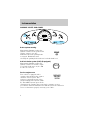
Before driving
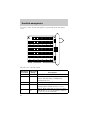
Introduction 2
Instrumentation 4
Controls and features 13
Seating and safety restraints 34
Starting and driving
Starting 59
Driving 63
Roadside emergencies 77
Servicing
Maintenance and care 95
Capacities and specifications 129
Reporting safety defects 139
Index 140
All rights reserved. Reproduction by any means, electronic or mechanical
including photocopying, recording or by any information storageand retrieval
system or translation in whole or part is not permitted withoutwritten
authorization from Ford Motor Company.
Copyright
r
1997 Ford Motor Company
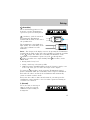
Contents
1

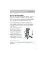
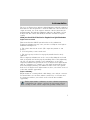
ICONS
Indicates a warning. Read the
following section on Warnings for a
full explanation.
Indicates vehicle information related
to recycling and other
environmental concerns will follow.
Correct vehicle usage and the
authorized disposal of waste
cleaning and lubrication materials are significant steps towards
protecting the environment.
WARNINGS
Warnings provide information which may reduce the risk of personal
injury and prevent possible damage to others, your vehicle and its
equipment.
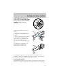
BREAKING-IN YOUR VEHICLE
There are no particular breaking-in rules for your vehicle. During the
first 1 600 km (1 000 miles) of driving, vary speeds frequently. This is
necessary to give the moving parts a chance to break in.
If possible, you should avoid full use of the brakes for the first 1 600 km
(1 000 miles).
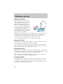
INFORMATION ABOUT THIS GUIDE
The information found in this guide was in effect at the time of printing.
Ford may change the contents without notice and without incurring
obligation.
Introduction
2

SPECIAL NOTICES
Using your vehicle as an ambulance
If your light truck is equipped with the Ford ambulance preparation
package, it may be utilized as an ambulance. Ford urges ambulance
manufacturers to follow the recommendations of the Ford incomplete
vehicle manual, Ford truck body builder’s layout book and the QVM
guidelines as well as pertinent supplements. For additional information,
please contact the Light Truck Body Builders Advisory Service
1–800–635–5560.
Use of your Ford light truck as an ambulance, without the Ford
Ambulance Preparation Package voids the Ford New Vehicle Limited
Warranty and may void the Emissions Warranties. In addition, ambulance
usage without the preparation package could cause high underbody
temperatures, overpressurized fuel and a risk of spraying fuel which
could lead to fires.
If your vehicle is equipped with the
Ford ambulance preparation
package, it will be indicated on the
Safety Certification Compliance
label. The label is located on the
driver’s side door pillar or on the
rear edge of the driver’s door. You
can determine whether the
ambulance manufacturer followed
Ford’s recommendations by directly
contacting that manufacturer. Ford
Ambulance preparation package is
only available on certain 7.3L Diesel
engine equipped vehicles.
Diesel-powered vehicles
Read the 7.3L Diesel Engine Owner’s Guide Supplement for information
regarding correct operation and maintenance of your diesel-powered
light truck.
Introduction
3

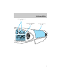
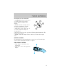
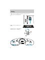
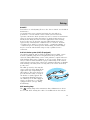
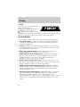
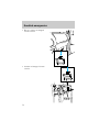
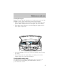
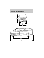
P R N D 2 1
18
8
H
L
+ -
10
20
30
40
50
60
70
80
90
100
0
20•km/h
40•
60
80
100
120
•
•
•
•
•140
•
0000
000
05
0
H
C
F
E
ON
OFF
RES
SET
ACCEL
COAST
OVERDRIVE
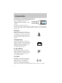
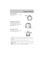
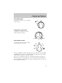
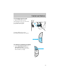
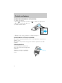
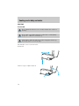
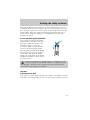
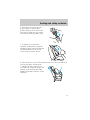
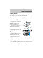
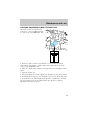
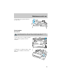
Instrument cluster
(pg. 6)
Gearshift (includes
overdrive button)
(pg. 27)
Auxiliary power
point*
(pg. 20)
Driver side air bag
(pg. 46)
Speed control*
(pg. 22)
Turn signal and
wiper/washer control
(pg. 21)
Headlamp control
(pg. 13)
*if equipped
Instrumentation
4

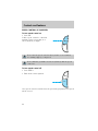
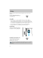
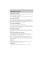
VOL-PUSH ON
AM
FM
BASS
TREB
BAL FADE
SEEK
TUNE
SCAN EJ
TAPE
DOLBY 8 NR
REW
1
FF
2
SIDE 1-2
3
4
5
6
ST
FM 1
FM 1
FAN
HI
LO
COOL
WARM
MAX
A/C
NORM
A/C
VENT
OFF
FLR
MIX
CLK
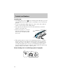
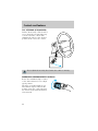
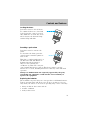
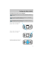
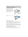
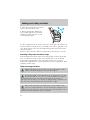
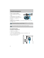
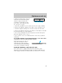
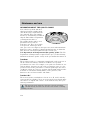
Climate control systems
(pg. 14)
Electronic sound system;
refer to Audio Guide
(pg. 20)
Passenger side air bag
(pg. 46)
Instrumentation
5

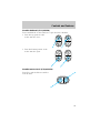
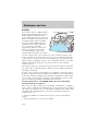
WARNING LIGHTS AND CHIMES
Brake system warning
Momentarily illuminates when the
ignition is turned to the position ON
and the engine is off. Also
illuminates when the parking brake
is engaged. Illumination after
releasing the parking brake indicates low brake fluid level.
Anti-lock brake system (ABS) (If equipped)
Momentarily illuminates when the
ignition is turned on and the engine
is off. If the light stays on, the ABS
needs to be serviced.
Service engine soon
Your vehicle is equipped with a
computer that monitors the engine’s
emission control system. This
system is commonly known as the
On Board Diagnostics System (OBD
II). This OBD II system protects the
environment by ensuring that your vehicle continues to meet
government emission standards. The OBD II system also assists the
service technician in properly servicing your vehicle.
0
10
20
30
40
50
60
70
80
90
100
20 km/h
40
60
80
100
120
140
H
L
160
MPH
000000
0000
BRAKE
18
8
SERVICE
ENGINE SOON
F
H
C
E
!
BRAKE
ABS
SERVICE
ENGINE
SOON
Instrumentation
6

The Service Engine Soon indicator light illuminates when the ignition is
first turned to the ON position to check the bulb. If it comes on after the
engine is started, one of the engine’s emission control systems may be
malfunctioning. The light may illuminate without a driveability concern
being noted. The vehicle will usually be drivable and will not require
towing.
What you should do if the Service Engine Soon light illuminates
Light turns on solid:
This means that the OBD II system has detected a malfunction.
Temporary malfunctions may cause your Service Engine Soon light to
illuminate. Examples are:
1. The vehicle has run out of fuel. (The engine may misfire or run
poorly.)
2. Poor fuel quality or water in the fuel.
3. The fuel cap may not have been properly installed and securely
tightened.
These temporary malfunctions can be corrected by filling the fuel tank
with good quality fuel and/or properly installing and securely tightening
the gas cap. After three driving cycles without these or any other
temporary malfunctions present, the Service Engine Soon light should
turn off. (A driving cycle consists of a cold engine startup followed by
mixed city/highway driving.) No additional vehicle service is required.
If the Service Engine Soon light remains on, have your vehicle serviced
at the first available opportunity.
Light is blinking:
Engine misfire is occurring which could damage your catalytic converter.
You should drive in a moderate fashion (avoid heavy acceleration and
deceleration) and have your vehicle serviced at the first available
opportunity.
Under engine misfire conditions, excessive exhaust temperatures
could damage the catalytic converter, the fuel system, interior
floor coverings or other vehicle components, possibly causing a fire.
Instrumentation
7

Transmission control indicator light (TCIL)
The word OFF located on the end
of the gearshift lever is the
transmission control indicator light
(TCIL).
The TCIL may flash steadily if a
malfunction is detected. If the TCIL is flashing, contact your Ford dealer
as soon as possible. If this condition persists, damage to the transmission
could occur.
Safety belt
Momentarily illuminates when the
ignition is turned to the ON position
to remind you to fasten your safety
belts. For more information, refer to
the Seating and safety restraints
chapter.
Charging system
Momentarily illuminates when the
ignition is turned to the ON position
and the engine is off. The light also
illuminates when the battery is not
charging properly, requiring
electrical system service.
Air bag readiness
Momentarily illuminates when the
ignition is turned ON. If the light
fails to illuminate, continues to flash
or remains on, have the system
serviced immediately.
Turn signal
Illuminates when the left or right
turn signal or the hazard lights are
turned on. If one or both of the
indicators stay on continuously,
check for a burned-out turn signal
bulb. Refer to Exterior bulbs in the Maintenance and care chapter.
OVERDRIVE
Instrumentation
8

High beams
Illuminates when the high beam
headlamps are turned on.
Oil pressure/Engine coolant
This light will come on when the
key is in the ON position and the:
• engine coolant temperature is
very high
• engine oil pressure is low
The light serves as a notice that a system needs your attention and to
check the engine coolant temperature gauge and the engine oil pressure
gauge.
Refer to Engine coolant temperature gauge and Engine oil pressure
gauge in this chapter for more information.
Safety belt warning chime
Chimes to remind you to fasten your safety belts.
For information on the safety belt warning chime, refer to the Seating
and safety restraints chapter.
Supplemental restraint system (SRS) warning chime
For information on the SRS warning chime, refer to the Seating and
safety restraints chapter.
Key-in-ignition warning chime
Sounds when the key is left in the ignition in the OFF/LOCK or ACC
position and either front door is opened.
Headlamps on warning chime
Sounds when the headlamps or parking lamps are on, the ignition is off
(and the key is not in the ignition) and the driver’s door is opened.
Instrumentation
9

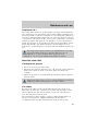
GAUGES
Speedometer
Indicates the current vehicle speed.
Fuel gauge
Displays approximately how much
fuel is in the fuel tank (when the
key is in the ON position). The fuel
gauge may vary slightly when the
vehicle is in motion. The ignition
should be in the OFF position while
the vehicle is being refueled. When
the gauge first indicates empty, there is a small amount of reserve fuel in
the tank. When refueling the vehicle from empty indication, the amount
of fuel that can be added will be less than the advertised capacity due to
the reserve fuel.
0
10
20
30
40
50
60
70
80
90
100
20 km/h
40
60
80
100
120
140
H
L
160
MPH
000000
0000
18
8
F
H
C
E
0
10
20
30
40
50
60
70
80
90
100
20 km/h
40
60
80
100
120
140
160
MPH
000000
0000
F
E
Instrumentation
10

Engine coolant temperature gauge
Indicates the temperature of the
engine coolant. At normal operating
temperature, the needle remains
within the normal area (the area
between the “H” and “C”). If it
enters the red section, the engine is
overheating. Stop the vehicle as
soon as safely possible, switch off
the engine immediately and let the
engine cool. Refer to Engine coolant in the Maintenance and care
chapter.
Never remove the coolant recovery cap while the engine is
running or hot.
This gauge indicates the temperature of the engine coolant, not the
coolant level. If the coolant is not at its proper level the gauge indication
will not be accurate.
Engine oil pressure gauge
This shows the engine oil pressure
in the system. Sufficient pressure
exists as long as the needle remains
in the normal range (the area
between the “H” and “L”).
If the gauge indicates low pressure,
stop the vehicle as soon as safely
possible and switch off the engine
immediately. Check the oil level. Add oil if needed (refer to Checking
and adding engine oil in the Maintenance and care chapter). If the
oil level is correct, have your vehicle checked at your dealership or by a
qualified technician.
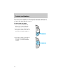
H
C
H
L
Instrumentation
11

Battery voltage gauge
This gauge shows the battery
voltage when the ignition is in the
ON position. If the pointer moves
and stays outside the normal
operating range (as indicated), have
the vehicle’s electrical system
checked as soon as possible.
Odometer
Registers the total kilometers
(miles) of the vehicle.
Trip odometer
Registers the kilometers (miles) of
individual journeys. To reset,
depress the control.
18
8
0
10
20
30
40
50
60
70
80
90
100
20 km/h
40
60
80
100
120
140
160
MPH
000000
0000
0
10
20
30
40
50
60
70
80
90
100
20 km/h
40
60
80
100
120
140
160
MPH
000000
0000
Instrumentation
12

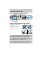
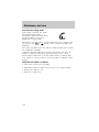
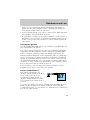
HEADLAMP CONTROL
• Pull the headlamp control toward
you to the first position to turn
on the parking lamps, tail lamps,
license plate lamps and marker
lamps.
• Pull the headlamp control toward
you to the outer position to turn
on the headlamps (in addition to
the previous lamps).
Daytime running lamps (DRL) (if equipped)
Turns the highbeam headlamps on with a reduced output. To activate:
• the engine must be running
• the headlamp control is in the OFF or Parking lamps position.
The Daytime Running Light (DRL) system will not illuminate the
tail lamps and parking lamps. Turn on your headlamps at dusk.
Failure to do so may result in a collision.
High beams
Push forward to activate.
Controls and features
13

Flash to pass
Pull toward you to activate and
release to deactivate.
PANEL DIMMER CONTROL
Use to adjust the brightness of the
instrument panel.
• Rotate
clockwise/counterclockwise when
it is in the on position.
• Rotate fully counterclockwise to
turn on the courtesy and cargo
lamps.
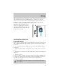
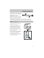
CLIMATE CONTROL SYSTEM
Heater only system (if equipped)
FAN
LO
HI
COOL WARM
VENT
FLR
OFF
MIX
Controls and features
14

Fan speed control
Controls the volume of air circulated
in the vehicle.
Temperature control knob
Controls the temperature of the
airflow inside the vehicle. On
heater-only systems, the air cannot
be cooled below the outside
temperature.
Mode selector control
Controls the direction of the airflow
to the inside of the vehicle.
• VENT-Distributes outside air through the instrument panel registers.
• FLR-Allows for maximum heating. Distributes outside air through the
floor ducts.
• OFF-Outside air is shut out and the fan will not operate.
• MIX-Distributes outside air through the floor ducts and the windshield
defroster ducts.
•
-Distributes outside air through the windshield defroster ducts.
It can be used to clear ice or fog from the windshield.
FAN
LO
HI
COOL
WARM
VENT
FLR
OFF
MIX
Controls and features
15

Operating tips
• In humid weather, select before driving. This will help to prevent
your windshield from fogging. After a few minutes, select any desired
position.
• To prevent humidity buildup inside the vehicle, don’t drive with the
climate control system in the OFF position.
• Don’t put objects under the front seat that will interfere with the
airflow to the back seats.
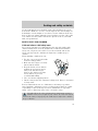
• Remove any snow, ice or leaves
from the air intake area (at the
bottom of the windshield under
the hood).
• When placing objects on top of your instrument panel, be careful to
not place them over the defroster outlets. These objects can block
airflow and reduce your ability to see through your windshield. Also,
avoid placing small objects on top of your instrument panel. These
objects can fall down into the defroster outlets and block airflow and
possibly damage your climate control system.
Manual heating and air conditioning system (if equipped)
FAN
LO
HI
COOL WARM
MAX
A/C
NORM
A/C
VENT
OFF
FLR
MIX
Controls and features
16

Fan speed control
Controls the volume of air circulated
in the vehicle.
Temperature control knob
Controls the temperature of the
airflow inside the vehicle.
Mode selector control
Controls the direction of the airflow
to the inside of the vehicle.
The air conditioning compressor will operate in all modes except VENT
and FLR. However, the air conditioning will only function if the outside
temperature is about 10°C (50°F) or above.
Since the air conditioner removes considerable moisture from the air
during operation, it is normal if clear water drips on the ground under
the air conditioner drain while the system is working and even after you
have stopped the vehicle.
FAN
LO
HI
COOL
WARM
MAX
A/C
NORM
A/C
VENT
OFF
FLR
MIX
Controls and features
17

Under normal conditions, your vehicle’s climate control system should be
left in any position other than MAX A/C or OFF when the vehicle is
parked. This allows the vehicle to “breathe” through the outside air inlet
duct.
• MAX A/C-Uses recirculated air to cool the vehicle. MAX A/C is noisier
than NORM A/C but more economical and will cool the inside of the
vehicle faster. Airflow will be from the instrument panel registers. This
mode can also be used to prevent undesirable odors from entering the
vehicle.
• NORM A/C-Uses outside air to cool the vehicle. It is quieter than MAX
A/C but not as economical. Airflow will be from the instrument panel
registers.
• VENT-Distributes outside air through the instrument panel registers.
However, the air will not be cooled below the outside temperature
because the air conditioning does not operate in this mode.
• OFF-Outside air is shut out and the fan will not operate. For short
periods of time only, use this mode to prevent undesirable odors from
entering the vehicle.
• FLR-Allows for maximum heating by distributing outside air through
the floor ducts. However, the air will not be cooled below the outside
temperature because the air conditioning does not operate in this
mode.
• MIX-Distributes outside air through the windshield defroster ducts and
the floor ducts. Heating and air conditioning capabilities are provided
in this mode. For added customer comfort, when the temperature
control knob is anywhere in between the full hot and full cold
positions, the air distributed through the floor ducts will be slightly
warmer than the air sent to the windshield defroster ducts. If the
temperature is about 10°C (50°F) or higher, the air conditioner will
automatically dehumidify the air to prevent fogging.
•
-Distributes outside air through the windshield defroster ducts.
It can be used to clear ice or fog from the windshield. If the
temperature is about 10°C (50°F) or higher, the air conditioner will
automatically dehumidify the air to prevent fogging.
Operating tips
• In humid weather, select before driving. This will prevent your
windshield from fogging. After a few minutes, select any desired
position.
Controls and features
18

• To prevent humidity buildup inside the vehicle, don’t drive with the
climate control system in the OFF position.
• Don’t put objects under the front seat that will interfere with the
airflow to the back seats.
• Remove any snow, ice or leaves
from the air intake area (at the
bottom of the windshield).
• If your vehicle has been parked with the windows closed during hot
weather, the air conditioner will do a much faster job of cooling if you
drive for two or three minutes with the windows open. This will force
most of the hot, stale air out of the vehicle. Then operate your air
conditioner as you would normally.
• When placing objects on top of your instrument panel, be careful to
not place them over the defroster outlets. These objects can block
airflow and reduce your ability to see through your windshield. Also,
avoid placing small objects on top of your instrument panel. These
objects can fall down into the defroster outlets and block airflow and
possibly damage your climate control system.
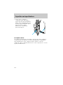
Auxiliary heater and air conditioner (if equipped)
If your vehicle is equipped with a factory installed auxiliary unit, the
front control panel will include separate controls for the front and rear
fans.
In addition an auxiliary unit fan
control is located in the headliner at
a location between the front and
rear seats.
OFF
HI
Controls and features
19

• To control the auxiliary fan with
this control, the rear fan switch
on the front control unit must be
in the rear control position.
• The auxiliary unit does not
provide for mixing of hot and
cold air. Adjustment of
temperature in the rear may be
accomplished by increasing or
decreasing the rear fan speed.
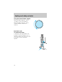
AUXILIARY POWER POINT
The auxiliary power point is located
on the instrument panel.
Do not plug optional electrical
accessories into the cigarette lighter.
Use the power point.
AUDIO SYSTEM
Refer to the “Audio Guide” for instructions on how to operate the audio
system.
REAR
OFF
HI
LO
REAR
CTRL
Controls and features
20
Page is loading ...
Page is loading ...
Page is loading ...
Page is loading ...
Page is loading ...
Page is loading ...
Page is loading ...
Page is loading ...
Page is loading ...
Page is loading ...
Page is loading ...
Page is loading ...
Page is loading ...
Page is loading ...
Page is loading ...
Page is loading ...
Page is loading ...
Page is loading ...
Page is loading ...
Page is loading ...
Page is loading ...
Page is loading ...
Page is loading ...
Page is loading ...
Page is loading ...
Page is loading ...
Page is loading ...
Page is loading ...
Page is loading ...
Page is loading ...
Page is loading ...
Page is loading ...
Page is loading ...
Page is loading ...
Page is loading ...
Page is loading ...
Page is loading ...
Page is loading ...
Page is loading ...
Page is loading ...
Page is loading ...
Page is loading ...
Page is loading ...
Page is loading ...
Page is loading ...
Page is loading ...
Page is loading ...
Page is loading ...
Page is loading ...
Page is loading ...
Page is loading ...
Page is loading ...
Page is loading ...
Page is loading ...
Page is loading ...
Page is loading ...
Page is loading ...
Page is loading ...
Page is loading ...
Page is loading ...
Page is loading ...
Page is loading ...
Page is loading ...
Page is loading ...
Page is loading ...
Page is loading ...
Page is loading ...
Page is loading ...
Page is loading ...
Page is loading ...
Page is loading ...
Page is loading ...
Page is loading ...
Page is loading ...
Page is loading ...
Page is loading ...
Page is loading ...
Page is loading ...
Page is loading ...
Page is loading ...
Page is loading ...
Page is loading ...
Page is loading ...
Page is loading ...
Page is loading ...
Page is loading ...
Page is loading ...
Page is loading ...
Page is loading ...
Page is loading ...
Page is loading ...
Page is loading ...
Page is loading ...
Page is loading ...
Page is loading ...
Page is loading ...
Page is loading ...
Page is loading ...
Page is loading ...
Page is loading ...
Page is loading ...
Page is loading ...
Page is loading ...
Page is loading ...
Page is loading ...
Page is loading ...
Page is loading ...
Page is loading ...
Page is loading ...
Page is loading ...
Page is loading ...
Page is loading ...
Page is loading ...
Page is loading ...
Page is loading ...
Page is loading ...
Page is loading ...
Page is loading ...
Page is loading ...
Page is loading ...
Page is loading ...
Page is loading ...
Page is loading ...
Page is loading ...
-
 1
1
-
 2
2
-
 3
3
-
 4
4
-
 5
5
-
 6
6
-
 7
7
-
 8
8
-
 9
9
-
 10
10
-
 11
11
-
 12
12
-
 13
13
-
 14
14
-
 15
15
-
 16
16
-
 17
17
-
 18
18
-
 19
19
-
 20
20
-
 21
21
-
 22
22
-
 23
23
-
 24
24
-
 25
25
-
 26
26
-
 27
27
-
 28
28
-
 29
29
-
 30
30
-
 31
31
-
 32
32
-
 33
33
-
 34
34
-
 35
35
-
 36
36
-
 37
37
-
 38
38
-
 39
39
-
 40
40
-
 41
41
-
 42
42
-
 43
43
-
 44
44
-
 45
45
-
 46
46
-
 47
47
-
 48
48
-
 49
49
-
 50
50
-
 51
51
-
 52
52
-
 53
53
-
 54
54
-
 55
55
-
 56
56
-
 57
57
-
 58
58
-
 59
59
-
 60
60
-
 61
61
-
 62
62
-
 63
63
-
 64
64
-
 65
65
-
 66
66
-
 67
67
-
 68
68
-
 69
69
-
 70
70
-
 71
71
-
 72
72
-
 73
73
-
 74
74
-
 75
75
-
 76
76
-
 77
77
-
 78
78
-
 79
79
-
 80
80
-
 81
81
-
 82
82
-
 83
83
-
 84
84
-
 85
85
-
 86
86
-
 87
87
-
 88
88
-
 89
89
-
 90
90
-
 91
91
-
 92
92
-
 93
93
-
 94
94
-
 95
95
-
 96
96
-
 97
97
-
 98
98
-
 99
99
-
 100
100
-
 101
101
-
 102
102
-
 103
103
-
 104
104
-
 105
105
-
 106
106
-
 107
107
-
 108
108
-
 109
109
-
 110
110
-
 111
111
-
 112
112
-
 113
113
-
 114
114
-
 115
115
-
 116
116
-
 117
117
-
 118
118
-
 119
119
-
 120
120
-
 121
121
-
 122
122
-
 123
123
-
 124
124
-
 125
125
-
 126
126
-
 127
127
-
 128
128
-
 129
129
-
 130
130
-
 131
131
-
 132
132
-
 133
133
-
 134
134
-
 135
135
-
 136
136
-
 137
137
-
 138
138
-
 139
139
-
 140
140
-
 141
141
-
 142
142
-
 143
143
-
 144
144


Ask a question and I''ll find the answer in the document
Finding information in a document is now easier with AI
Related papers
-
Ford 2002 F-53 Motorhome Chassis Owner's manual
-
-
-
-
-
-
Ford 1998 User manual
-
-
-
Other documents
-
Lincoln Navigator Owner's manual
-
-
-
Lincoln 2002 Blackwood Owner's manual
-
-
-
Mercury 1999 Grand Marquis Owner's manual
-
-
 Bar's Leaks 1400 User guide
-
 airmaster 70005 User manual

