Genie 2060L Owner's manual
- Category
- Garage Door Opener
- Type
- Owner's manual
This manual is also suitable for

©pe_'at et} and
e
3559935907
2060
3060
AC POWERED SCREW DRIVE OPENERS
COHTEHTS
Warranty Information ...................2
Your Documentation Package ..........3
Safety Information ..................... 4
Safety Features ......................... 4
Important Installation Instuctions ....... 4
Pre-lnstallation Checklist .............. 5-8
Adjustments ......................... 9-10
Programming the Remote Control ..... 11
Installing lightbulb and lens ............ 12
Scheduled Maintenance ............... 13
Troubleshooting Guide ............. 14-15
Wiring Diagram ........................ 16
Parts Lists and Exploded Views ...... 17-18
Accessories ............................ 19
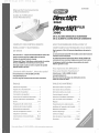
(k)MRLETE WITH II,_I"ELLICO[}E
!E!OTE COST ;;'_r_ AH© ,<I_;D_ ........,J RuL s ,sES II
For up to 7'-6" tall Doors. (Extension Kit available for 8' Doors)
Included Wall Control MUST be installed prior to Operation of
this Garage Door Operator.
Safe-T-Beam ®Safety Reverse System Must be Installed and
the Force Controls MUST be Properly Set to dose door.
This Equipment meets or exceeds all Federal, State and UL325
Safety Requirements.
Please call us: 1-800-3S-GENIE (354-3643)
www.geniecompany.com
Please have Model information
ready when calling.

What s ceve_'ed?
Anydefectinmaterialandproductworkmanshipfrompersonal,normalhouseholduse
inaccordancewiththeOwner'sManual.
Fo_'hew o_9?
MODEL2060L...20 years on motor, 3 years all other parts.
MODEL3060L... Lifetime* on motor,3 years all other parts.
MODEL3060C ... Lifetime _ on motor, 3 yearsall other parts.
*Lifetime = Foras long asyou own your home.
Who gets rise, v_:_a_s'a_ty
This warranty is limited to the consumer who originally purchased the product.
Thiswarrantyappliesonlyto unitsinstalledandoperatedwithinthecountrywhere
theywerepurchased.
L, ¢_ tat _sns
IMPLIEDWARRANTIES,INCLUDINGTHOSEOF FITNESSFORA PARTICULARPURPOSEAND
MERCHANTABILITY(AN UNWRITTENWARRANTYTHATTHE PRODUCTISFITFORORDI-
NARYUSE),ARELIMITEDTO ONEYEARFROMTHEDATEOF PURCHASE.GENIEWILL NOT
PAYFOR:LOSSOF TIME;INCONVENIENCE;LOSSOF USEOFYOURGENIEPRODUCTOR
PROPERTYDAMAGECAUSEDBYYOURGENIEPRODUCTORITSFAILURETOWORK;ANY
SPECIAL,INCIDENTALORCONSEQUENTIALDAMAGES;ORANY DAMAGESRESULTING
FROMMISUSEOR MODIFICATIONOFYOURGENIEPRODUCT.
Some states and provinces do not allow limitations on how long an implied warranty
lastsor the exclusion of incidental or consequential damages, sothe above limitations or
exclusions may not apply to you.
This warranty isthe only one wewill give on your Genie product, and it sets forth all our
responsibilities regarding your Genie product.There are noother express warranties.
State and province rights:This warranty givesyou specific legal rights, andyou may also
haveother rights which vary from state to state and province to province.
How to get wa_'_'a_ty se_'v<e,
To obtain warranty servicefor your Genie product, you must provide proof of the date
and place of purchase of the product.
Call the GenieConsumer Connection toll free at 1.800.354.3643to speakin person to a
trained Genie representative for assistance in diagnosing the problem and arranging
to supply you with the required parts for do-it-yourself repairs.Trained service repre-
sentatives areavailable Monday-Friday, 8:00a.m.- 11:00p.m.,Eastern Time,and on
Saturday, 10:00a.m.to 8:00p.m.,Eastern Time (subject to holidays) You may also get
the information you need at www.geniecompany.com.
You also may obtain warranty service from Genie authorized dealers by calling the
Genie Customer Service at 1.800.354.3643or by visiting www.geniecompany.com
before scheduling warranty service.If warranty service is provided by anauthorized
dealer, Geniewill provide all required parts under warranty at no charge to you, but
the dealers are independent business people and may render a bench or service call
charge for their services.Genie will not reimburse you or otherwise be responsible for
those charges.
Wesuggest that you retain your original packing material in the event we choose to
repair or replaqce your Genie Product and request that you ship it to us.Besure to
include your name, address,telephone number, proof of date and place of purchase
and a description of the operating problem.After repairing or replacing, your Genie
product, we will ship it to your home at no cost to you for parts and labor, but you will
have to pay a minimum of %.00 for shipping and handling charges.
Your choice of either one of the above-described serviceoptions isyour exclusive
remedy under this warranty.
What th wa_'_'a_ty does _ot cove_'
This warranty does not cover batteries (which are considered replaceable parts), installa-
tion, commercial use,defects resulting from accidents,damage while in transit to our
service location or damage resulting from alterations, misuse or abuse,lack of proper
maintenance, unauthorized repair or modification of the product, affixing of any attach-
ment not provided with the product, programming of the Remote Control Devices,
Safe-T-Beam®adjustment/cleaning, staples through wiring, pinched or broken wires,
Carriage disengaged, ForceControl adjustments, door out of balance, broken springs
or cables,power outages, use of extension cords, missing or damaged parts on dis-
counted, clearanced, final sale or taped cartons, phantom operations (labor isnot cov-
ered if Opener is functioning properly while technician is in garage),fire, flood, or actsof
God,or other failure to follow the Owner's Manual.
FORANSWERS:CALL1.800.354.3643
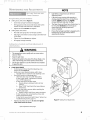
Pleasenote the following information,so it isavailable if you
needto call us.
Date Purchased / /
SerialNumber
Operator Model
Remote Control Model
Dealer Name
DealerAddress
City
State
Zip
Model Number and
Serial Number are
located on front
panel inside
the lens.
NOTE
Please keep original or photocopy of your sales
rece!ptwith this manual for future reference should
service ever be required.
Visit Our Website at: www.geniecompany.com
SAVETHESEINSTRUCTIONS

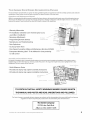
The documentation provided with your opener has been carefully designed and organized to make the assembly, operation,and continued
maintenance of your product as easy and safe as possible.This material consists of two main items.
While it is recommended that all documents be retained for future reference, this manual should contain most of the information that you
will need over the lifetime of your product.The manual is designed in a "flip-flop"configuration with the english version in one half of the
book and the spanish / french version in the other half.The basic contents of this manual are:
i,.ii ", i ,, ..
i}F SIII
¢ a , )A;, A
Warranty Information
Pre Installation Checklist to be reviewed prior to any
assembly or installation
Necessary Adjustments
Programming Remote Devices _e
Maintenance and Troubleshooting
Parts Explosions
Accessory Order Form
Door Opener Association Safety and Maintenance Brochure (DASMA)
Entrapment Warning Label - To be Adhered in close proximity
to wall control
siisl_i _c. ce
%<. SiOl_
<h / c _;,.. i.
iDI=I_iII_
[ ill]q .xl_i(' .i,;'Ksi()l]
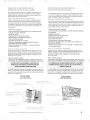
Assembly a_'_d/_}stallatio_'_ Peste_
This poster is intended to give a convenient lay flat media to be used at the site of assembly and installation. Color coding is used to
highlight steps and other information as clearly as possible.This poster is Tri-Lingual with english instructions highlighted with a blue
background.The basic contents of this Poster are:
(_e _e
Quick Reference Poster ....................._
Pictorial and step by step opener assembly mstruclons -.- _:_ ......
nsta at on nstruct ons . ,_ .........::........._., _, .Pictorial and step by step opener ........_;'--,
") .... . _.i._., _///'
(> f' /_:o{' / _ ..........................................
IT IS CRITICAL THAT ALL SAFETY WARNINGS MARKED CLEARLY IN BOTH
THE MANUAL AND POSTER ARE READ, UNDERSTOOD AND FOLLOWED.
The Genie Company is constantly striving to improve our products and the documentation that comes with them. If you have any
suggestions or ideas for improving this product and it's documentation, please forward them to:
The Genie Company
22790 Lake Park Blvd.
Alliance, Ohio 44601-3498

2060-3060 eng.qxd 11/9/05 11:02 AM Page 4
i
'\ b/
........_i]i17.......
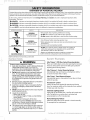
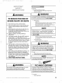
OVERVIEW OF POTENTIAL HAZARDS
Overheaddoors arelarge,heavyobjects that movewith the help of springsunder high tension and electric motors. Sincemoving objects,springs under
tension, andelectric motorscan causeinjuries, your safety andthe safetyof others depend on you readingthe information in this manual. Ifyou have
questions or do not understand the information presented, callThe GenieCompany.or your local GenieDistributor.
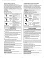
In this section, and those that follow, the words Danger, Warning and Caution are used to emphasize important safety
information. The word:
.i_ DANGER: indicates an imminently hazardous situation which, if not avoided, will result in death or serious injury.
WARNING: indicates a potentially hazardous situation which, if not avoided, could result in death or serious injury.
-_ CAUTION: indicates a potentially hazardous situation which, if not avoided, may result in injury or property damage.
The word NOTE is used to indicate important steps to be followed or important considerations.
WARNING: • Keep people clear of opening while door is moving.
Could result in death • Do Not allow children to play with the door operator.
or serious injury. • Do Not operate a door that jams or one that has a broken spring.
MOVINGDOOR
ELECTRICALSHOCK
HIGHSPRINGTENSION
WARNING:
Could result in death
or serious injury.
WARNING:
Could result in death
or serious injury.
• Turn off power before removing operator cover.
• When replacing cover, make sure wires are not pinched or near
moving parts.
• Operator must be properly grounded.
• Do Not try to remove, repair or adjust springs or anything to
which door spring parts are fastened, such as,wood blocks,
steel brackets, cables or other like items.
• Repairs and adjustments must be made by a trained door
system technician using proper tools and instructions.
WARNING:
TO REDUCE THE RISK OF SEVERE INJURY OR DEATH:
1 READAND FOLLOW ALL SAFETY,INSTALLATIONAND
OPERATIONINSTRUCTIONS.If you have any
questions or do not understand an instruction, call
your authorized Genie installation professional.
2 Do Not install operator on an improperly balanced
door. An improperly balanced door could cause
severe injury. Repaffs and adjustments to cables,
spring assembly, and other hardware must be made
by a trained service person using proper tools and
instructions.
3 Remove all ropes, and disable all locks connected to
the door before installing operator.
4 Install door operator 7 feet or more above the floor.
Mount the emergency release knob 6 feet above
the floor.
5 Do Not connect the operator to the source of power
until instructed to do so.
6 Locate the control button:
Within sight of door.
At a minimum height of 5 feet, so small children
cannot reach it.
• Away from all moving parts of the door.
7 Install the entrapment WARNING label next to the
wall button or console. Install the emergency release
tag on, or next to, the emergency release
8 The operator must reverse when the door contacts a
1-1/2 inch high object on the floor at the center of
the doorway.This is about the size ofa 2"x 4" board
laid flat.
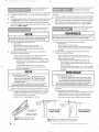
Safe-T-Beam ® (STB) Non-Contact Reversing System
Places an invisible beam across door opening, that reverses
the door during down travel to the fully open position if
anything passesthrough beam.
Safe-T-Reverse ® Contact Reversing System
Automatically stops and reverses a closing door within 2
seconds of contact with an object.
Safe-T-Stop ® Timed Reversed System
Automatically opens a closing door, if door does not close
within 30 seconds.
ForceGuard ® Control
Used to set the force required for opening and closing
door. For maximum safety, set the minimum force required
to fully open and close door.
Automatic Lighting System
Light bulbs up to 60 Watts max., used for safer entries and
exits.The lights turn on when door isactivated and
automatically turn off 4.5 minutes later.
Manual Emergency Release
Allows the garage door to be opened or closed manually
for emergencies or maintenance.
4
I <_I"Js_<, %%%1,<÷Is_, 01]11-I<_ iiy 1(oI]l
........\X7.......
i
........................._:i ........................

2060-3060 eng.qxd 11/9/05 11:02 AM Page 5
i
'\ b/
This Opener includes parts and supplies needed to install in most garages and
connect to most garage doors. There are many variations of garages and garage
doors. Afew additional parts and supplies may be needed to install Opener into
your garage and connect to your garage door. While checking items listed
below, note any additional items you will need.
• 12'+ Tape Measure ° Pencil ° Ladder ° Level
WARNING:
If your door sticks, binds, or is out of
balance, have it adjusted by a Genie Factory
Authorized Dealer. Door springs, cables,
pulleys, brackets and associated hardware
are under extreme tension and can cause
serious injury or death.
........<17.......
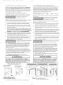
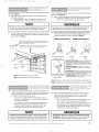
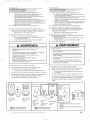
Check condition of vertical stile in center of door (Figure 2), and its connection
to door's top and bottom beams.
A If door frame is nailed together and not a solid connection, door frame
must be braced or reinforced before installing Opener.
B If door is"lightweight"(made with frame and skin - not solid), door
(including door frame) must be braced or reinforced before
installing Opener.
C A door opener reinforcement bracket may also be needed to connect
garage door to Opener's Door Bracket. This Opener is designed for
installation on a properly braced sectional door or solidly braced
one-piece door.
D Contact your Genie Factory Authorized Dealer or dealer of your garage
door for any necessary bracing and a door opener reinforcement
bracket (if needed) before proceeding.
E If you have a wooden door, measure door's thickness. (1/4" x 2") Lag
Screws are included for installing Door Bracket onto door. If your door
is less than 2"thick, brace door or use shorter Door Bracket Lag
Screws (1/4" x 1-1/4"- not included)
KEEPFEETCLEAR OF DOOR
........<17.......
I;_L 6HP_ZH ] O I_iRAs]"lOF_l
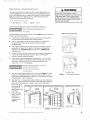
A Raisedoor, check alignment and see if it moves freely (Figure l). Ifdoor
appears out of alignment, binds, or does not move smoothly, contact a
Genie Factory Authorized Dealer or dealer of your garage door for repairs
and adjustments to door mechanism.
B Raise door to 3' - 4' above ground and carefully let go. Door should stay
stationary. Slight movement is acceptable. More than slight movement
means door is out of balance. Contact a Genie Factory Authorized
C
Dealer or dealer of
your garage door
for repairs and
adjustments to door
mechanism.
Check door type.
Make a note of
whether it is a
sectional or a
one-piece door
(Figure 2).
SECTIONALDOOR,TORSIONSPRINGS SECTIONALDOOR,EXTENSIONSPRINGS
Torsion Extension
Header Springs Springs
Figure 1
Center
Stile
Figure 2 Note Door Type
One-Piece Door
Checking door balance
ONE-PIECEDOOR,TRACKLESS
Header Area
Center Stile
5
i
.........................L_IN........................
i

2060-3060 eng.qxd 11/9/05 11:02 AM Page 6
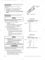
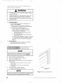
Measure garage door height (7'-6", 8'-0", or taller) with
tape measure.
A If door height is 7'-6" or less, continue with Check Step 4.
B If door height is 8'-0", you need a Rail Extension
Kit. (Figure 3) (See Accessories Order Form, page 19).
C If door height is taller than 8'-O",you will require a different rail.
Contact an Genie Customer Service Representative at 1-800-
35-GENIE.
CH_iG DOO_ M_it%[;@H:{/_:E_
Figure 3 Rail Extension Kit
Rail Extension for
8' door
........\ii7 .......
NOTE
The header isa heavily reinforced section of the wall just
above the top of the garage door opening.
A
B
Find vertical center line of door and header:
• Close door.
• Measure door width at top.
• Mark a point at center of door and on header directly
above door. Draw a center line to connect points.
Find Header Bracket mounting height (Figure 4):
(Do not attach Header Bracket).
• Raise door, watching top edge of door and stop door
when its edge reaches its highest point.
• Measure distance ("H") from top edge of door to floor.
- For sectional doors, add 2-1/2" to"H" Mark a point
on center line. Bottom of Header Bracket will be
installed here.
- For one-piece doors, add 6" to "H" Mark this point on
center line. Bottom of Header Bracket will be
installed here.
HEADER
SECTIONAL DOOR
H
ONE-PIECE DOOR
........\ii7 .......
NOTE
C
6
For both types of doors:
- If the ceiling in your garage is so low that there is
not at least a 3" space above the Header Bracket
mountingpoint, contact a Genie Factory
AuthorizedDealer.
If a door spring isin the way, place the Header
Bracket above the spring. Do Not move the door spring.
WARNING:
Door springs are under extremely high tension and should be
handled ONLYby a trained professional.
Check wall for a stud or a solid header at your mark:
(If checking a finished wall, a stud finder may be helpful).
• If location is above Header, a 2"x 6" board must be
screwed to studs beside your mark with at least two Lag
Screws and Flat Washers (not provided).
• Transfer your mark to new mounting board.
HEADER
H ÷ 6"
Figure 4 Find Highest Point of Travel
.........................L_IN........................

2060-3060 eng.qxd 11/9/05 11:02 AM Page 7
i
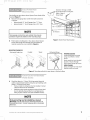
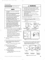
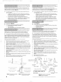
Check ceiling or space above where Opener Power Head will be
mounted (Figure S):
A Measure from garage door center line mark toward rear
of garage:
° Approximately 10' back if garage has a 7' 6" door.
° Approximately 11' back if garage has an 8' 0" door.
NOTE
Since garage construction varies widely, there may be
hardware required in addition to the mounting straps.
B Find location of ceiling joist or truss above where Opener
Power Head will be and estimate type and quantity of
materials needed for your installation (Figure 6).
Check for 15 Amp, 120 Volt
......_ grounded outlet or wiring box
within 3 feet of
'\- S: . &£ Power Head. J
il V//
.... :--T&:.........
.......;"" k]ii':
for 7-1/2'
Figure S Check Power Head location
........\X7.......
MOUNTING EXAMPLES
Perforated Angle Iron
Conduit Wood
Perforated Straps
FINISHED CEILINGS
Locate ceiling joists or trusses
using a stud finder or similar
device.
Attach angle iron (not included
to joists or trusses through
finish material using Lag Screws.
OPEN CEILINGS
Straps and angle iron may attach
directly to joists or trusses.
Figure 6 Mounting methods for open beam or finished ceilings
........\X7.......
A
Check that there is a 15 Amp 120 Volt grounded electrical
outlet or grounded permanent wiring box (per building code)
within 3' of Opener Power Head:
• If not, an outlet or wiring box must be installed. Contact
a licensed electrician for installation.
• If building codes require permanent wiring, Power Head
must be partially disassembled to install appropriate
wiring in place of Power Cord (See Installation Poster).
NOTE
Permanent wiring must be installed by a Licensed
Electrician. Not all Genie Factory Authorized Dealers are
Licensed Electrician's. Contact someone who is a Licensed
Electrician.
7
i
.........................':i ........................

2060-3060 eng.qxd 11/9/05 11:02 AM Page 8
i
(_HECH SAH> -BBJWv _'
MOL/;K_"BY5 [_;_,, ,RE L,OC£]"/OH
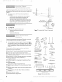
Check for wood garage frame, jamb, or masonry at mounting location
(6" above floor) with attachment tabs facing away from garage door
(Figure 7).
A
Ifyou cannot mount Safe-T-Beam® Mounting Bracket to
wood frame:
• Concrete screws and concrete anchors (not included)
must be used to mount Brackets on masonry with
attachment tabs facing away from garage door.
• Safe-T-Beam ®Mounting Bracket Extensions may be used
(not included - available from a Genie Factory Authorized
Dealer or through Accessories Order Form on page 19).
A
B
Tools (Figure 8):
Additional tools to make installation easier:
• Slotted and phillips screw-driver bits
° Stud finder
° Sheet-metal cutting snips
Source
Safe-T-Beam ®
Mounting Bracket
Sensor
:2-_--1__-
i]l t = --;=±
J 'hi
i _ilJi ' : ).z_-_
To0o
i ," II 6" Bracket6
II J above
6 Ill floor
_,q_!,J,L
Figure 7 Mounting Safe-T-Beam ® Components
........_]i17.......
Doo_<{Locls
Check that the garage door locks, rope, and T-Handles are removed
from the garage door before starting the installation.
Ifyour garage does not have a separate entry door, it is highly
recommended to install a Genie Emergency Release Kit (GER-2).
Emergency Release Kit lets you open garage door from outside if
there is a power failure. (Please see Accessories Order Form on
page 19.)
Befo_e 9ob_{F u_tBe_)get _y terns _'_d tools
_'_eeded fo_ you_
[] Safe-T-Beam ®Sensor Mounting Bracket Extensions (dealer)
[] Garage door opener reinforcement bracket (dealer)
[] Garage door frame reinforcement brackets, screws, bracing
or reinforcement kits (dealer)
[] Lag Screws (1-1/4") for a wood door less than 2" thick (store)
[] Electrical outlet and/or wiring (supplied by a
licensed electrician)
[] Sufficient angle iron or strapping for hanging Power Head
(store)
[] 60 Watt light bulbs
(Rough service bulbs recommended)(store)
[] GER-2 Emergency Release Kit for entry during power failure
(store)
[] Wood for header, ceiling, and/or door bracing reinforcement
(if needed)
[] Masonry fasteners for Safe-T-Beam ® Bracket installation,
(if needed)
[] Masonry drill bit (if needed)
[] Extension Kit (for 8' garage doors)
Drill
1/16" 5/32"
Drill Bit Drill Bit
6' or 7'
Step Ladder
Adjustable Wrench
Hammer Wire
Stripper
Phillips Screwdriver
Wrench
( I_/ I)1
Flat Blade Screwdriver
Safety Glasses
£]
Pencil
888888
1/4" 5/16" 8/8" 7/16" 1/2" 9/16"
Hack Saw Sockets
Carpenter's Level
Figure 8 Recommended Tools
........q17.......
8
i
.........................L_IN........................

2060-3060 eng.qxd 11/9/05 11:02 AM Page 9
i
/i%
........_i]17.......
_£1q _E A q%.,EAHD _E}LtUSTMEKI%
tCOICI 0", , ..... _"_=*
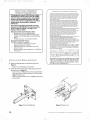
IIougB Setti_'_g of Lissit Swit_:cBes
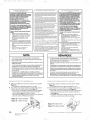
A Setting Close Limit Switch (Figure 9):
• Check that Carriage Assembly is disengaged.
• With garage door fully closed, slide Close Limit Switch
toward Carriage until white lever is fully lifted.
• Tighten Set Screw. Do Not over-tighten.
B Setting Open Limit Switch:
• Manually open garage door to full open position.
° Slide Open Limit Switch toward Carriage until white lever
is fully lifted.
• Tighten Set Screw. Do not over-tighten.
• Re-engage Carriage Assembly.
kis_it :s,4J c_e,s
WARNING
• The garage door opens rapidly, and cancauseserious
injury or death.
• Keepthe path clear.
• Position the ladder to the side of the Power Head so it is
clear of all moving parts of the Opener and the door.
• Set the door Opener to use the minimum force needed
to open the door.
A CLOSE ADJUSTMENT
• On front panel of Power Head find adjusting screw
marked "CLOSE" (Figure 9).
• Gently turn screw counterclockwise until it stops.
- Very little force is required to turn adjusting screw.
• Press Wall Console to close garage door.
- Observe if door stops at"CLOSE" limit switch.
If door is fully closed--adjustment is finished.
Go to "OPEN" Adjustment.
- If door stops but is not fully closed,
a. Measure distance between bottom of door
and floor.
b. Move "CLOSE" Limit Switch that same distance
toward door.
- If door stops and/or reverses before reaching the
"CLOSE" Limit Switch
a. Slightly increase CLOSE Force setting (clockwise).
- If door reverses after contacting floor, move Limit
Switch toward Power Head.
- If door fails to move, check Safe-T-Beam ®System. See
Troubleshooting Section, page 14.
• Tighten Limit Switch Set Screw. Do not over-tighten
(strip) Limit Switch Set Screw.
NOTE
o
Little effort is required to turn the Force
Adjusting Knobs.
• If the door stops moving while opening or
closing, adjust the Open Force or Close Force
Controls slightly clockwise (to slightly
increase the force) and retry the step.
• The Open Force and Close Force Controls are to
be set to the minimum force necessary to
ensure the door smoothly opens and
closes completely.
• Ensure the Carriage Assembly isengaged and is
between the two Limit Switches before
operating the Opener.
FORCE
CONTROLS
Figure 9 Making Force Adjustments
,/i'%
........\117.......
Open adjustment next page.
9
i
.........................L_IN........................

2060-3060 eng.qxd 11/9/05 11:02 AM Page 10
i
'\ b/
WARNING
• A moving grage door can cause serious injury or death.
• Keepthe path clear.
• Position the ladder to the side of the Power Head so it is
clear of all moving parts of the Opener and the door.
• Set the door Opener to use the minimum force needed
to open the door.
........ki17.......
B OPEN ADJUSTMENT
• On front panel of Power Head find adjusting screw
marked "OPEN" (Figure 9).
• Gently turn screw counterclockwise until it stops.
- Very little force is required to turn adjusting screw.
• Press Wall Console to close garage door.
- Observe if door stops at"OPEN" limit switch.
If door is fully open--adjustment is finished.
- If door stops but is not fuly open,
a. Measure distance between bottom of door
top of door opening.
b. Move "OPEN" Limit Switch that same distance
toward Power Head.
- If door stops before reaching the"OPEN" Limit Switch
a. Slightly increase OPEN Force setting (clockwise).
- If door fails to move, see Troubleshooting Section,
pages 15.
C Run Door Opener
• Cycle opener a few times to double check settings.
Repeat adjustment steps as necessary.
........ki17.......
SITTIH6 <CI _U'_+{°"__= Jl.= &_=
I,_IVIB,sI I<iIIHCTlOH
NOTE
Limit Switch and Force Adjustments must be completed
before checking the contact reverse function (Figure 10 ).
A Open garage door using Wall Console.
B Lay a 2" x 4" board flat in center of doorway.
C Close door using Wall Console.
D Check that door stops and reverses within 2 seconds after it
contacts board:
• If door does not reverse, decrease Close Force until
door reverses.
• If door still does not reverse, move Limit Switch
toward door.
E Check Safe-T-Beam ® System operation:
• If beam is blocked, door will not close.
NOTE
Thedoor mustcontact the 2" x 4"board beforethe Carriageactivates
the CloseLimit Switch. Ifnot,readjustthe CloseLimit Switch.
2" x 4" board
laid flat
Figure 10 Checking Contact Reverse
10
i
.........................L<IN........................

2060-3060 eng.qxd 11/9/05 11:02 AM Page 11
'\ 1./
........_:]:7.......
}"E
NOTE
EachRemote Control must be programmed
separately.
• The Remote Controls will not cause the door
Opener to close the garage door if the Safe-T-
Beam®System is malfunctioning.
• When programming the Remote Controls, they
must be at least 24" from the Antenna Wire.
• Ifthe red Learn Indicator Light blinks
approximately 4 times per second,
programming has stopped. If programming
has stopped, repeat the above steps.
• EachButton on a 2 or 3 Button Remote Control
isfor a different Opener. You cannot use more
than one Button per Remote, per Opener.
• A maximum of seven Remote Controls or
Wireless Keypads can be stored into the
Receiver at one time. If a Remote Control
becomes lost, or if you want to delete a Remote
Control or Wireless Keypad, see"To EraseAll
Receiver Memory."
A To program one Button of a Remote Control (Figure 12):
• Locate Learn Button and Learn Indicator Light near
Terminal Strip on Power Head (Figure 13).
• Press and release Learn Button. Red Learn Indicator
Light will blink 2 times per second.
• Press Remote Control Button once within 30
seconds. Red Learn Indicator Light will stay lit.
• Press Remote Control Button again. Red Learn
Indicator Light will go out, indicating that
memory is stored.
B Program each additional Remote using step A above
(up to seven).
7b
A
E%ase All _es_etes f_os_ Pewe_ Mead _{e_"_'_e_y
Press and hold Learn Button on Power Head for 10
seconds or until Learn Indicator Light goes out.
Memory is erased:
• Program Transmitter/Receiver again as needed.
To _eplace _Res_ete Co_d_'ol Ba e_y'
A FOR NON-FLASHLIGHTMODELS
• Pop off the back of the transmitter.
- Use coin, pen, screwdriver or any similar device.
- Replace old Battery with new coin type battery.
• Replace back of remote.
B FOR FLASHLIGHT MODELS
• Slide open battery cover.
- Replace old Battery with new AAA battery.
• Replace battery cover.
WARNING
A moving garage door may causeserious injuryor death.
• Keeppeople clear of opening while door is moving.
• Do not allow children to play with the Remote Controls.
If the Safety Reversedoes not work properly:
• Closethe door and disconnect the Opener using the
Emergency ReleaseCord.
• Do not usethe door Opener,Remote Controls, or
Wireless Keypad.
• Referto the door and door Opener Owner's Manuals
before attempting any repairs.
[Ies_ote Co_ _01 Opera io_
A Press Button on Remote Control. Garage door will move.
B Press Button again. Garage door will stop:
• The door automatically stops at the end of the open or
close cycle.
C Press Button again. Garage door will reverse.
315 Mhz _-f_-_'-_ _ 315 Mhz
Frequency _I Frequency
__ Switch _ Switch
390 Mhz
1 Button Compact Remote 3 Button Compact Remote
w/Docking Station w/Docking Station
Figure 12 Genie Remote Controls
Receiver Learn
Code Button
Receiver
,2 S_ i
Figure 13 Learn Code Button and Indicator Light
D Some Remote Controls are equipped with a flashlight.The
logo is the button which operates the light. There is a
backlight under the button.When it does not light, it
indicates the battery needs replaced.
Frequency
Flashlight Button Switch
J
\\ /'
1 Button Remote 3 Button Remote 3 Button Large
w/Flashlight w/Flashlight Remote
w/Flashlight
Figure 14 Genie Remote Controls
11
........\::7 .......
,f] "_
.........................L_:N........................

2060-3060 eng.qxd 11/9/05 11:02 AM Page 12
'\ b/
........_i]17.......
Your garage door opener (GDO) features a unique
dual frequency remote control system for reliable
service in today's crowded airwaves. Overcrowded
airwaves may intermittently interfere with GDO's
remote control system. The dual frequency feature
greatly reduces the possibility of unwanted
interference.
The receiver in the GDO's powerhead can receive
signals at 315 AND 390 MHz.The remote isfactory
set at 315 MHz. See Figure 12 on page 11 for
frequency selector switch.
Switch your remote control frequency when:
• Remote does not have adequate range.
• Remote works inconsistently with fresh battery
installed - LEDfeedback lights up when pressing
button.
• Programming your car's HomeLink ® system.
Toprogram a HomeLink ®device:
(This GDO is HomeLink ®compatible.)
• Use a small flat screwdriver to switch the
frequency selector to 390 MHz.
• Follow the HomeLink ® instructions in your car
owner's manual.
• Reset the remote control frequency to 315 MHz for
everyday use.
tH _LLL/6HT_ULB akan+LEHS
Installtwo 60Wattlightbulbs(notincluded)into LightSockets
(Figure13):
• Roughservice,130Voltbulbsarerecommended.
Holdthe lens,with the bottomhingespointingup,againstthe power
headmetalfront cover(Figure 14).
• Insert(2)#8-32x3/8"PhillipsHexHeadScrewsthrough the Bottom
hingesand into holesprovidedin metalfrontcoverof PowerHead
(Figure14).Tightenscrews.
• FlipLensup andfastenwith (2)#8-32x 3/8"PhillipsPanHeadScrews
whereindicated.
/
Transmitters comply with all United Statesand Canadian legal requirements
as of the date of manufacture. No warranty is made that they comply with all
legal requirements of any other jurisdiction. If transmitters are to be used in
another country, the importer must determine compliance with any local
laws and regulations which may differ from United Statesand Canadian
requirements prior to use,
Lostransmisores cumplen con todas las reglamentaciones Jegalesde los
Estados Unidos ydel Canadfi, en la fechade fabficaci6n. Ninguna garantia
se da que cumplan con todas asreglamentaciones legales de ninguna otra
jurisdicci6n+ Si los transmisores se van a utilizar en otto pais,el importador
debe determinar si cumplen con las reglamentaciones y leyes localesque
puedan serdiferentes a lasreglamentaciones de los EstadosUnidos y del
Canad4, antes de usar los mismos+
Les_metteurs sont conformes _ la r_glementation am@icaine et canadienne
compter de bur date de fabrication. Aucune garantie n'est stipuJ_e
indiquant qu'ils sont conformes _ routes les prescriptions juridiques d'autres
autorit_s. Siles @metteurssont utilis@sdans d'autres pays,il incombe
I'importateur d'en d_terminer leur conformit_ aux lois et r@gleslocales
pouvant diff@rerde celles dest_tats-Uniset du Canadaavant toute
utilisation desdits @metteurs+
Sendeger_te entsprechen allen gesetzlichen Bestimmungen in den USAund
Kanada zum Zeitpunkt der Herstellung.Wir Obernehmen keine
Gew_ihrleistung for die Einhaltung aller gesetzlichen Bestimmungen in
anderen L_indern.Sollen Sendeger_itein anderen L_ndern eingesetzt werden,
so muss der Importeur vor dem Gebrauch sicherstellen, dassdie Sendegerate
auch solchen Iokalen Bestimmungen entsprechen, welche von den
Bestimmungen der USAund Kanadas abweichen+
........_i]17.......
Figure 13 Install Lightbulbs Figure 14 Attach Lens
12
........................._<i........................

2060-3060 eng.qxd 11/9/05 11:02 AM Page 13
'\ b/
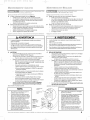
MPOR rAH T
- WARNING
TO REDUCE THE RISK OF
SEVERE INJURY OR DEATH
1
2
4
5
6
READ AND FOLLOW ALL INSTRUCTIONS.
Never let children operate or play with the Door
Controls. Keep the Remote Control away from
children.
Always keep the moving door in sight and away
from people and objects until the door is
completely closed. NO ONE SHOULD CROSSTHE
PATHOFTHE MOVING DOOR.
NEVERGO UNDERA STOPPED,PARTIALLY
OPEN DOOR.
Test Opener monthly. The door MUST reverse on
contact with a 1-1/2" high object (or a 2" x 4"
board laid flat) at the center of the doorway on the
floor. After adjusting either the Force or the Limit
of travel, retest the Door Opener. Failure to adjust
the Opener properly may cause severe injury
or death.
When possible use the Emergency Release only
when the door is closed. Use caution when using
this Release with the door open. Weak or broken
springs are capable of increasing the rate of door
closure and increasing the risk of severe injury
or death.
KEEPGARAGE DOORS PROPERLYBALANCED. See
arage door Owner's Manual. An improperly
alanced door increases the risk of severe injury
or death. Have a Genie Factory Authorized Dealer
make repairs to cables, spring assemblies, and
other hardware.
8 SAVETHESEINSTRUCTIONS.
_ WARNING
Usethe Wall Console included with Opener. Any other
wall console can cause the Opener to operate
unexpectedly and the light to stop working.
A Monthly:
• Door springs and door hardware:
- Oil door roller, bearings, and hinges using silicone
lubricant or light oil.
WARNING
Do not operate door automatically or manually if springs
are broken. Contact a Genie Factory Authorized Dealer for
service or call Customer Service at 1-800-35-GENIE.
Balance Door.
- Close door.
- ReleaseCarriage Assembly from Rail Assembly by pulling
the Emergency Release Knob towards the door.
- Raisedoor manually 3'- 4' and verify that door stays at
that position. SeeCheck Step 2on page 5.
NOTE
When the door is 3'- 4' above the ground, the door
should stay open. Slight movement is acceptable. If
the door moves too much, contact a Genie Factory
Authorized Dealer for service or call Customer Service at
1-800-35-GENIE.
- Reattach CarriageAssembly to Rail Assembly:
a. Pull the Emergency Release Knobtoward Power Head.
b. Close door.
Contact ReverseTest.
- Perform Adjustment 2 on page 10.
WARNING
If the door fails to reverse on contact with the board,
adjust the Close Force Control asspecified in Set Limit
Switches and Force Controls on page 10. If the Opener
still fails,contact a Genie Factory Authorized Dealer for
service or call Customer Service at 1-800-35-GENIE.
B Yearly:
• Wipe off old excess lubricant from Drive Screw.
• Lubricate Drive Screw with Genie Lubricant (GLU-3)
NOTE
Use ONLYGenie Lubricant (GLU-3). Other lubricants
may damage the Opener.
GLU-3
Lubricant
FCC AND IC CERTIFIED
All devices comply with Part 15of the FCCRules.
Operation issubject to the following two conditions: (1)
this device may not cause harmful interference, and (2)
this device must accept any interference received, includ-
ing interference that may cause undesired operation.
C As needed
• Replace lightbulbs.
13
........\::7 .......
.........................Y:N........................

2060-3060 eng.qxd 11/9/05 11:02 AM Page 14
Source (Red LED) Sensor (Green LED)
ON ON
OFF OFF
OFF ON
2 BLINKS,Pause
(Repeat) ON
2 BLINKS, Pause
(Repeat)
3 BLINKS, Pause
(Repeat)
OFF
ON
ON
4 BLINKS, Pause
(Repeat)
Possible Problem
Normal operation
• Power Head not powered
• Wiring from Power Head bad
• Wiring to Source missing or bad
• Power has been interrupte
• Beam not aligned
• Beam obstructed
• Sensor defective
• Wire to Sensor missing or bad
_,. Sensor defective
• Sensor receiving interference
• Source not sending pulses
• Source defective
Solution
None required
• Check breakers, fuses, plugs
• Check wiring for obvious shorts
• Check wiring
• Remove power and reapply
• Check Source, Sensor alignment
• Check for obstruction
• Contact Customer Service
• Check wiring
• Contact Customer Service
• Determine source of interference
• Check for interference from sun-
light or a source unit on an
adjacent door
• Contact Customer Service
• Contact Customer Service
• Contact Customer Service
14

2060-3060 eng.qxd 11/9/05 11:02 AM Page 15
fi%
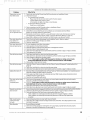
Problem
Opener does not run
from Wall Control
Door Opener starts
for no apparent reason
Door starts down, then
stops before it is
completely closed
Door starts down, then
stops and goes backup
Door will only run closed
Door will only run open
Lightswill not turn off
Door starts up, but stops
before it is
completely open
Operator runs,but door
doesnot move
Wall ConsoleVacation
Lockfunction does
not work
Noisy Operation
6e_ e_'a _oubles} oot _}g
What To Do
1.
2.
Check Lock switch on Wall Control (seeWall Console section on Installation Poster).
Check Power Source:
• For Grounded Plug Connection.
- Plug alamp into the electrical outlet used for the door opener.
a. If lamp lights, power source is good.
b. If lamp does not light, check fuse or circuit breaker.
• For Permanent Wiring Connection.
- Check fuse or circuit breaker.
3. Check connections (seeWall Console section on Installation Poster):
• At Power HeadTerminals and Wall Control.
1. CheckWires to ensure that they are not cut (Stapes can cut insulation and short Wires)
Replace any shorting Staples and shorted Wires.
2. Was Remote Control lost or stolen? Ifso,erase all Remote Control codes from Receiver's memory
and reprogram for remaining remote controls. (See EraseAll Receiver Memory on page 11).
:3. Ensure that no Buttons are stuck"pushed-in"on Wall Console or any Remote Controls.
1. Check Close Limit Switch setting (page 9and Installation Poster). Adjust as needed.
2. Check ForceSetting (page 9).Adjust as needed.
:3. Check for shorted wires.
1. If a new installation, check Door Arm position.
2. Checkoperation of ContactReversefunction.
3. CheckSafe-T-Beam®Systemfor beam obstruction or misalignment of Lenses.
4. CheckSafe-T-Beam®Systemdiagnostic code.
S. CheckCloseForceadjustment (seeSetLimit Switchesand ForceControls on page 9). Adjust asneeded.
6. Checkgarage door for binding.
1. CheckOpen Limit Switch for ashort circuit andfor proper wiring.
2. CheckOpen Forceadjustment (seeSet Limit Switchesand ForceControlson page9). Adjust asneeded.
3. Checkcondition of garagedoor and door spring(s).
4. WA_::i'H1_6:If you suspectaproblem with the garage door hardware or springs,contactaGenie
FactoryAuthorized Dealer forservice,or contactCustomerServiceat 1-800-35-GENIE.
S. Checkposition of LockSwitchon Console.
®
1. CheckSafe-T-Beam®Systemasdetailed in the Safe-T-Beam SystemSelf-diagnosticTroubleshooting Chart
(page 14).
2. CheckCloseLimit Switch for a short circuit andfor proper wiring.
:3. CheckCloseForceadjustment (seeSetLimit Switchesand ForceControls on page 9).Adjust asneeded.
1. DisconnectWiresconnecting WallConsoleto PowerHead(see"WallConsoleInstallation"-on Installationposter).
Checktheir condition and either replaceor reconnect.
2. Until areplacement WallConsolecan be obtained, disconnect WallConsoleand useonly RemoteControls
or WirelessKeypad to operate Opener.
:3. Check for non-compatible wall control.
1. Check (ensure) that garage door and Opener are in good repair,properly lubricated, and properly
balanced asdetailed in Maintenance Section.
2. W/:iSH H6: If you suspecta problem with the garage door hardwareor springs,contacta Genie Factory
Authorized Dealer forservice,or contactCustomerServiceat 1-800-35-GENIE.
3. CheckOpen Limit Switchfor a short circuit andfor proper wiring.
4. CheckOpen Forceadjustment (seeSet Limit Switchesand ForceControls on page 9).Adjust asneeded.
1. EnsureCarriageAssembly isengaged to RailDriveScrew (seeInstallCarriageAssembly -INSTALLATIONPOSTER).
2. CheckForceadjustment (seeSetLimit Switchesand ForceControls on page 9).Adjust as needed.
3. Checkthat all sectionsof RailDriveScrew areturning when Motor runs. Ifnot:
• Checkcondition (not cracked,split,or broken) and placement of Coupler. Replaceasneeded.
• Checkcondition (not cracked,split,or broken) and placement of Collarand Clip. Replacethem
asneeded.
1. EnsureCarriageAssembly isin contact with CloseLimit Switch.
2. Checkwhen door isfully closed,that Carriageactivates CloseLimit Switch. Ifnot, adjust position of Close
Limit Switch (Seepage9).
1. Besureallfastenersaretight.
2. Check (ensure) that garage door and Opener are in good repair,properly lubricated, and properly
balanced asdescribed in Maintenance Section (page 13).
15
.........................Y:N........................

2060-3060 eng.qxd 11/9/05 11:02 AM Page 16
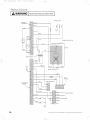
'\ b/
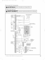
I Opening Cover May Cause Electric Shock
POWER CORD
16
.........................L_:IN........................

2060-3060 eng.qxd 11/9/05 11:02 AM Page 17
.........................rib .......................
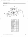
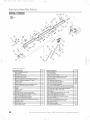
[1] Head Assembly
%
........q17.......
Rowe_ Hea{t }'%r°_-_
Item
1
A
B
C
D
E
F
G
H
J
K
L
M
N
R
4
5
39
41
42
48
49
PartName
PowerHead Assembly
Cover(bySeriesModel)
Front Plate Assembly
Light Socket
Motor Parts
ReceiverAssembly
Capacitor (BySeries/Model)
Opto Wheel
Opto-Luctor Assembly
SequencerAssembly
Circuit Board Bracket
Transformer
Terminal Strip
No.8-32 x 1/2" HexHead Screw
w/Lockwasher
No.8-32 x 3/8" Slot HexHead
Screww/Lockwasher
Capacitor Isolator
1/4-20 Shoulder Bolt
1/4" Flange Nut
Coupler
No.8-32 x 3/8" Phillips
Hex HeadScrew
No.8-32 x 3/8" Phillips
PanHead Screw
Mounting Straps
Light Lens
I
I
I
2
I
I
I
I
I
I
4
I
I
1
1
2
2
1
2
2
1
........q17.......
17
i
.........................L_IN........................

2060-3060 eng.qxd 11/9/05 11:02 AM Page 18
........................_ ........................
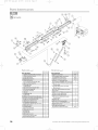
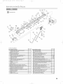
[3]Rail Assembly
........\L7 ....... ........\L7 .......
Item Part Name
I Power Head Assembly (see page 5)
3 Rail Assembly(3-piece)
3A First Rail Section
3B Middle RaiISection
3C End Rail Section
4 I/4"-20 Hex Head Shoulder Bolt
5 I/4"-20 Hex Flange Nut
6 Carriage Stop
7 Rail Clamps
8 5/16"Hex Head Shoulder Bolt
9 5/16"Hex Flange Nut
I0 Carriage Assembly
11 Collar
12 Retaining Clip
13 Rail Strap
15A Open Limit Switch Assembly (grey)
15B Close Limit Switch Assembly (brown)
16 #8-32 x 3/8"Hex Head Screw
17 Emergency Release Cord
18 Emergency Release Knob
19 Emergency Release Tag (not shown)
20 Header Bracket
21 Door Bracket
22 I/4"x 2"Lag Screw
23 Straight Door Arm
24 Clevis Pin
25 Cotter Pin
26 Curved Door Arm
27 3/8"x 7/8"Hex Head Bolt
28 3/8"Hex Flange Nut
1
1
1
1
1
2
2
1
4
8
13
1
2
2
1
1
1
2
1
1
1
1
1
8
1
2
2
1
2
2
Part Name
29 Wire(not shown) _-95 ft
30 Insulated Staples (not shown) _- 30
31 Wall Button (not shown) varies
33 Wall Console (not shown) varies
34 #6 x 1-1/4"Pan Head Screw 2
35 Entrapment WARNING Label (not shown) 1
36 Safe-T-Beam (STB)Sensor (green LED)
(not shown I
37 Safe-T-Beam Source (red LED)
(not shown) I
38 Safe-T-Beam Bracket (not shown) 2
39 Coupler I
40 #I0 x 1-1/4"Phillips Hex Head Screw 4
41 #8 x 3/8"Hex Head Screw 4
42 #8 x 3/8"Pan Head Screw 2
43 Safety and Maintenance Guide
(not shown) I
44 Wire Clip 4
46 5/16"x 3/4"Hex Head Bolt 5
47 I/4"-20 x 3/4"Self-tapping Screw 3
48 Mounting Straps 2
49 Light Lens (see page 5) I
50 Remote Control (not shown) varies
18
i
.........................L<N........................

2060-3060 eng.qxd 11/9/05 11:02 AM Page 19
i
'\ b/
:J<:tJ, •o,•, ,.sl s AOO)S801){ (£dellOl
_'o/1 lu/aif'e (lie 0o TII718](i@ d@8 8ooessokes i)OL/OLPiI@-i)ONO (!0 !,lfr7+i_flO
For additional accessories not shown• visit our website at www.geniecompany.com
Para accesorios adicionalesno mostrada, visite nuestro sitio web en www.geniecompany.com
pour les accessoires supplernentaires pas rnontr& visiter notre site web _ www.geniecompany.com
(GICTD-1)1-Button CompactRemote-Allowsremoteoperationof garagedoor.
ComprimaelMandodeDistancia- Proporcionaroperacionremotode lapuertadelgaraje.
T_l_commandecompacte-Permettreopeation _loign"de portedegarage. P/N 35674R $36.50
(GIF TD-1)1-ButtonFlashlightTransmitter- RemoteControllerwitha Flashlight.
1abrochatransmisordelinterna -Directorremoto conunalinterna.
l-boutenner I'_metteur delampedepoche - LecontrGleur_loign_avecde lampede poche.
P/N 35657R
$45.00
(GICTD-3)3-ButtonCompactRemote- Allowsremote operationof 3garagedoors.
De3 botonesComprimaelMandodeDistancia-ProporciGnaroperaciGnremoto detreslaspuertasdelgaraje.
3-boutennerlaT_l_commandecompacte-Permettreopeation eloign'trois portes
degarage. PIN 35694S $50.00
(GWC-2W)DeluxeWallConsole-OperatesGarageDoor.Independentlightcontrol.Securityvacationlock. _
Consoladelujodepared- Accionalapuertadelgaraje.Controlde luz independiente.Cerradurade
seguridadparavacaciones.
LaConsoledseluxedeMur- Actionnelaporte degarage.Commanded'_clairageind@endante.
Interrupteurde verrouillagedes_curit& P/N 35661 R $35.00
(GWKPD)DualFrequencyWirelessKeypad-OperatesIntellicode_GarageDoorOpenerswithout RemoteControl
orkey.
Sistemadeentradaportecladonum_ricoinal_mbrico- Accionalosabridoresde puertasdegarajeIntellicode'sin
controlremotoo Ilave.
Syst_med'ouvre-porte de garage_ claviersansfil- Actionnelesouvre-portede garageavecIntellicode'sans
tGIGcommandeniclG. P/N 35691R $50.00
(G/U-3) 3/4 oz,ScrewDriveLubricant-Ensuresproper equipmentwearprotection.
3/4onceLubricante de tornillo accionar-Aseguracomponentecorrectoprotecci6npordeterioro.
Laonza3/4Lubricant dela vis - Garantircomponantexactparsyst_meddenseversuser. P/N 35218AS $5.00
(GW-2) UniversalWallButton- Providesadditionalconvenientinsideoperationofdoor.
Botbndepareduniversal-Proporcionaoperacionconvenientede lapuertadesdeelinterior.
W
Bouton muraluniversel-ActionneI'ouvre-portede I'inteieur du garage. P/N 35693R $3.75
(GPS-S)PerfectStop- Ensuresperfectparking.
StopPerfecto- Aseguraelestacionamientoperfecto.
$
ButoirPerfect Stop'-Permetde stationneralaperfection dansle garage. P/N 35677R $4.00
(6ABX8)QuietLift ExtensionKit- An Extensionthatincreasesthe travel ofanOpenertoaccommodatean
eightfoot door.
Juego de extensibnde cadenadeslizable -Unaextensi6nparaaumentarlaIongitudde labarandadeChain
Glide,paraacomodarunapuertade8pies(2,43m).
N_cessairede prolongementdu coulisseau- Rallongede prolongeantlacoursedeI'ouvre-porteChainGlide
pouruneportede2,4m(8pi)de hauteur. P/N 35663R $32.00
(LCGX-8) ChainLiftExtensionKit- AnExtensionthat increasesthe travelofan Openerto accommodatean _
eightfoot door.
Juegodeextensibn decadenadeslizable-Unaextensi6nparaaumentarlaIongitudde labarandade Chain
Glide,paraacomodarunapuertade8pies(2,43m).
N_cessairede prolongementdu coulisseau-Rallongede prolongeantla coursede I'ouvre-porteChainGlide
pouruneportede2,4m(8pi)de hauteur. P/N 35679R $32.00
(GSX-8) DirectLiftExtension Kit- AnExtensionto increasetravel of anOperatorto accommodate
eightfoot door.
JuegodeextensibndeslizantedeScrewDrive- Unaextensi6nparaaumentarlacarrerade unabridor
deslizable,paraacomodarunapuertade 8pies(2,43m.). _ _'_ _
N_cessairede rallongedu ScrewDrive- Rallongede prolongeantla
coursedeI'ouvre-portepour uneporte de2,4m (8pi) dehauteur.(GIRU-1T) P/N 35678R $32.00
(60WATT)Enhanced/RoughServiceLightBulb-Ensuresproperequipmentcomparability. /'_
Bombilla de 60Vatios- Aseguracomponentecorrectode sistema.
Eclairagede60 WATT-Garantircomponantexactparsysteme. P/N 26210A.S $2.73
(GER-2)Emergency Release Kit- Provides accessto garage from outside in the event of
an electrical power failure.
Juego de pica-porte de pestillo - Permitir entrtada desde por fuera de garaje porque corte
de electrico.
N_cessaires de D_clenchement de secours - Le necessaire de declenchement
de secours est con_upour vous permettre d'acc_der a votre garage depuis
]'ext@ieur en cas de panne de courant et ]orsqu'iL P/N 35675R $20.00
STB Adapter Brackets (2) - Used in conjunction with standard STBBrackets.They provide
additional clearance and mounting options. _
El adaptador pone entre par_ntesis (2) - Usado en uni6n con par_ntesis uniformes de
montar de STB,ellos proporcionan el espacio libre adicional junto con mortar lasopciones.
Crochets d'adaptateur (2) - Utilis_ conjointement avec STBstandard monter les crochets,
ils fournissent le d_gagement suppl_mentaire avec monter d'options. P/N 34439R.S $4.37
How many?
sQuantos?
Comment
beaucoup?
C,JYO@Y/F 1
1
-
 2
2
-
 3
3
-
 4
4
-
 5
5
-
 6
6
-
 7
7
-
 8
8
-
 9
9
-
 10
10
-
 11
11
-
 12
12
-
 13
13
-
 14
14
-
 15
15
-
 16
16
-
 17
17
-
 18
18
-
 19
19
-
 20
20
-
 21
21
-
 22
22
-
 23
23
-
 24
24
-
 25
25
-
 26
26
-
 27
27
-
 28
28
-
 29
29
-
 30
30
-
 31
31
-
 32
32
-
 33
33
-
 34
34
-
 35
35
-
 36
36
-
 37
37
-
 38
38
-
 39
39
-
 40
40


Genie 2060L Owner's manual
- Category
- Garage Door Opener
- Type
- Owner's manual
- This manual is also suitable for
Ask a question and I''ll find the answer in the document
Finding information in a document is now easier with AI
in other languages
- français: Genie 2060L Le manuel du propriétaire
- español: Genie 2060L El manual del propietario
Related papers
-
Genie Garage Door Opener 3627336241 User manual
-
Genie 3630436275 User manual
-
-
-
-
-
-
Genie Excelerator Series User manual
-
-
Other documents
-
 PortaSeal G9x7 Installation guide
-
Unbranded GLU-R Operating instructions
-
Chamberlain 1022 User manual
-
 Genie Company 6072H-BV Owner's manual
-
Ryobi GD201 Owner's manual
-
-
-
 The Genie Company a Division of Overhead Door PowewrMax XL 4060 User manual
-
-


