Green LEG
on on off off off
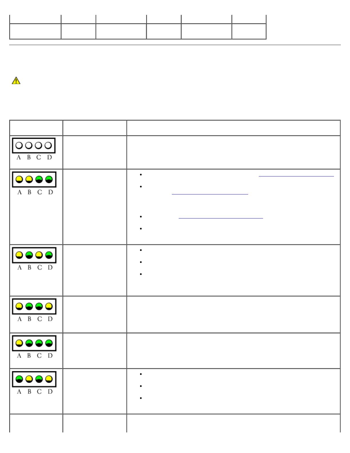
Diagnostic Lights
CAUTION: Before you begin any of the procedures in this section, follow the safety instructions located in
the Product Information Guide.
To help you troubleshoot a problem, your computer has four lights labeled "A," "B," "C," and "D" on the back panel. The lights
can be yellow or green. When the computer starts normally, the lights flash. After the computer starts, all four lights display
solid green. If the computer malfunctions, the color and sequence of the lights identify the problem.
Light Pattern Problem Description Suggested Resolution
The computer is in a
normal off condition or
a possible pre-BIOS
failure has occurred.
Plug the computer into a working electrical outlet and press the power button.
Memory modules are
detected, but a
memory failure has
occurred.
If you have one memory module installed, reinstall the memory module
and restart the computer.
If you have two or more memory modules installed, remove the
modules, reinstall one memory module
, and then restart the computer.
If the computer starts normally, reinstall an additional module. Continue
until you have identified a faulty module or reinstalled all modules
without error.
If available, install properly working memory of the same type into your
computer.
If the problem persists, see "Contacting Dell" in your Owner's Manual for
instructions on obtaining technical assistance.
A possible graphics
card failure has
occurred.
If the computer has a graphics card, remove the card, reinstall it, and
then restart the computer.
If the problem still exists, install a graphics card that you know works
and restart the computer.
If the problem persists or the computer has integrated graphics, see
"Contacting Dell" in your Owner's Manual for instructions on obtaining
technical assistance.
A possible floppy or
hard drive failure has
occurred.
Reseat all power and data cables and restart the computer.
A possible USB failure
has occurred.
Reinstall all USB devices, check cable connections, and then restart the
computer.
Memory modules are
detected, but a
memory configuration
or compatibility error
exists.
Ensure that no special memory module/memory connector placement
requirements exist (see Specifications).
Verify that the memory modules that you are installing are compatible
with your computer (see Specifications).
If the problem persists, see "Contacting Dell" in your Owner's Manual for
instructions on obtaining technical assistance.
A possible expansion
card failure has
1. Determine if a conflict exists by removing a card (not a graphics card)
and restarting the computer.


