Tyan S1846 Tsunami ATX User manual
- Category
- Motherboards
- Type
- User manual
This manual is also suitable for

Tyan S1846 Tsunami ATX
Motherboard User’s Manual
Revision 1.20
Copyright © Tyan Computer Corporation, 1998. All rights reserved. No part of this
manual may be reproduced or translated without prior written consent from Tyan
Computer Corp.
All registered and unregistered trademarks and company names contained in this
manual are propery of their respective companies including, but not limited to the
following.
AMIBIOS is a trademark of American Megatrend Incorporated.
Windows is a trademark of Microsoft Corporation.
IBM, PC, AT, PS/2 are trademarks of IBM Corporation.
INTEL, Pentium II, Celeron are trademarks of Intel Corporation.
S1846 Tsunami and Tsunami-ATX are trademarks of TYAN Computer Corporation.
Information contained in this publication has been carefully checked for accuracy and
reliability. In no event will Tyan Computer be held liable for any direct or indirect,
incidental or consequential damage, loss of use, loss of data, or other malady resulting
from errors or inaccuracies of information contained in this manual. The information
contained in this document is subject to change without notice.
PRINTED IN USA.

Table of Contents
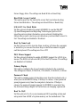
1. Introduction.......................................................................4
Overview..................................................................... 4
Icons........................................................................... 5
Hardware Specifications/Features................................. 6
Software Specifications.................................................8
Technical Support......................................................... 8
Returning Merchandise for Service................................9
2. Board Installation..............................................................10
Unpacking....................................................................10
Installation....................................................................10
Setting Jumpers............................................................ 25
3. Onboard Resource Settings..............................................26
Quick Reference for Jumpers........................................26
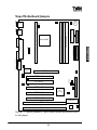
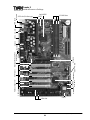
Map of Motherboard Jumpers....................................... 27
Hardware CMOS & Password Reset............................30
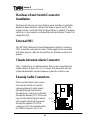
Soft Power Connector...................................................31
Speaker Connector Installation...................................... 31
Hardware Reset Switch Connector Installation...............32
External SMI................................................................32
Chassis Intrusion Alarm Connector................................ 32
Ensoniq Audio Connectors.............................................32
CMOS RTC.................................................................33
Flash EEPROM........................................................... 33
RAM Installation.......................................................... 34
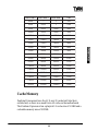
Cache Memory.............................................................35
Frequently Asked Questions.......................................... 36
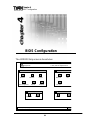
4. BIOS Configuration...........................................................38
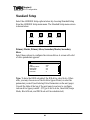
Standard Setup............................................................. 40
Advanced Setup........................................................... 44
Chipset Setup............................................................... 50
Power Management Setup............................................ 56
PnP/PCI Setup.............................................................60
Peripheral Setup........................................................... 64

Supervisor and User Security.........................................67
Anti-Virus Security....................................................... 68
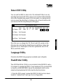
Detect IDE Utility.........................................................69
Language Utility........................................................... 69
Flash Writer Utility........................................................69
5. System Resources.............................................................72
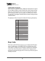
POST Checkpoint Codes.............................................. 72
Beep Codes................................................................. 80
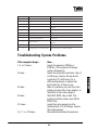
Troubleshooting System Problems..................................81
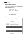
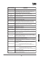
Displayed Error Messages............................................ 82
Glossary.......................................................................84

http://www.tyan.com
4
Chapter 1
Introduction
Overview
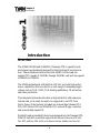
The S1846 (S1846S and S1846SLA) Tsunami ATX is a quality, high
performance motherboard designed for Intel Pentium II microproces-
sors. This motherboard utilizes the Intel 440BX AGPset and can
support CPU speeds of 233MHz through 450MHz, and host bus speeds
of 66MHz to 100MHz.
The S1846 motherboard, with built-in AGP slot, provides high perfor-
mance capabilities that are ideal for a wide range of demanding appli-
cations such as CAD, CAM, CAE, desktop publishing, 3D animation,
and video production.
This integrated system board achieves high reliability with numerous
features and yet is small enough to be supported in an ATX form
factor. Some of the features included are onboard dual channel PCI
PIO, BUS Master IDE and UltraDMA/33, onboard floppy controller,
and onboard high speed I/O.
Flexibility and expandability have been designed into the Tsunami ATX.
With I/O and drive controller support built onboard, the one AGP slot,
five PCI and two ISA slots (one shared, seven usable) are free for
chapter 1
Introduction

http://www.tyan.com
5
INTRO
numerous add-on expansion cards.
Remember to take a look at TYAN Computer’s web site located at
http://www.tyan.com. There you can find information on all of TYAN’s
products along with FAQs, distributors list, drivers, and BIOS setting
explanations.
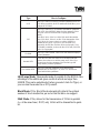
Icons
In order to help you navigate this manual and set up your system, we
have added several icons to our format.
This icon alerts you to particularly important details regarding the setup
or maintenance of your system. This icon often appears
next to information that may keep you from damaging your
board or system. While we will often point out the most
vital paragraphs in a chapter, you should always read every word in the
text. Failing to do so can lead to exasperation and expense.
Wherever possible, we have included step-by-step instruc-
tions for setting up your system, which are indicated by
this icon. However, it is in your best interest to read an
entire section (and perhaps the entire manual) before you
begin to fiddle with your motherboard.
While we have alerted you to potential dangers in several
places in the manual with this icon, these warnings should
not be regarded as the whole of your safety regimen. Never
forget that computers are electrical devices, and are
capable of delivering a shock. Prevent damage to yourself and to your
board: always ensure that your system is turned off and unplugged
whenever you are working with it, and that you are equipped with a
static safety device.
!
important!
procedure
1.
2.
3.
warning

http://www.tyan.com
6
Chapter 1
Introduction
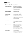
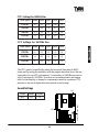
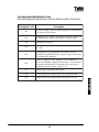
Hardware Specifications/Features
Processor Information •One SEC slot (Slot One type)
•66MHz to 100MHz bus support
(BIOS selectable)
•Pentium II 233-450MHz
•Supports Celeron CPUs
Chipset Information •Intel 440BX AGPset
•Intel PIIX4e controller
•National 309 Super I/O chipset
Voltage and Power •ATX power supply connector
Information •+12V power source for DC fan
onboard
•3.3V DRAM support
•Utilizes GTL+ bus to reduce power
consumption and EMI
Main Memory •Up to 768MB onboard
•Three 168-pin DIMM sockets
•Supports 100MHz SDRAM with
SPD
System Management •Optional National LM79 and LM75
ASICs with onboard alarm for
monitoring temperature, supply
voltages, and fan speed
•Intel LANDesk Client Manager
software (with LM79 installed)
•Chassis intrusion detection capable
Expansion Slots •One 32-bit AGP slot
•Five 32-bit PCI BUS Master slots
•Two 16-bit ISA slots
•One shared, seven usable slots

http://www.tyan.com
7
INTRO
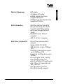
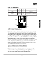
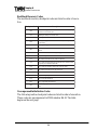
Physical Dimensions •ATX design
•12 inches x 8.25 inches
•S1846S requires Intel Venus
compatible I/O shield
•S1846SLA requires Intel Caveman
compatible I/O shield
BIOS Information •AMI Plug and Play flash BIOS
•Deep Green, Energy Star, ACPI,
Year 2000, and PC98 compliant
•Soft power-down, multiple boot
options
•Win98/NT5 ready, DMI 2.0
compliant
•PCI 2.1, APM 1.1 compliant
Disk Drive & System I/O •Two PCI bus mastering EIDE
channels
•Supports EIDE CD-ROMs
•PIO Mode 3 & 4 (up to 17MB/sec
DTR)
•UltraDMA/33 bus mastering mode
(up to 33MB/sec DTR)
•Support for two floppy drives (up to
2.88MB)
•Two serial ports (16550 UARTs)
•One ECP/EPP parallel port
•One IR (InfraRed) I/O interface port
•Two USB rev 1.2 (universal serial
bus) connectors
•One PS/2 mouse connector
•One PS/2 keyboard connector

http://www.tyan.com
8
Chapter 1
Introduction
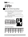
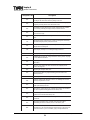
Ensoniq ES 1371 AudioPCI •AC97 Codec
(S1846SLA only) •Uses a single, shared IRQ
•High performance PCI bus master
•Spatial enhanced 3D sound (SWS)
•Wavetable synthesis built in
•Joystick, Audio in, Speaker,
Microphone connectors
Warranty •3 year manufacturer’s warranty
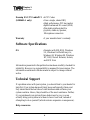
Software Specifications
OS •Operates with MS-DOS, Windows
3.x, Windows for WorkGroup 3.x,
Windows 95, Windows 98, Windows
NT, OS/2, Novell Netware, Solaris,
and SCO Unix
Information presented in this publication has been carefully checked for
reliability. However, no responsibility is assumed for inaccuracies. The
information contained in this document is subject to change without
notice.
Technical Support
If a problem arises with your system, you should turn to your dealer for
help first. Your system has most likely been configured by them, and
they should have the best idea of what hardware and software your
system contains. Hence, they should be of the most assistance. Further,
if you purchased your system from a dealer near to you, you can
actually bring your system in to them to have it serviced, instead of
attempting to do so yourself (which can have expensive consequences).
Help resources:

http://www.tyan.com
9
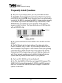
1. See FAQ and beep codes sections of this manual.
2. See Tyan web site for FAQ, bulletins, driver updates, etc.
http://www.tyan.com
3. Contact your dealer or distributor for help BEFORE calling Tyan.
4. Check the Tyan user group: alt.comp.periphs.mainboard.tyan
5. Email Tyan tech support: [email protected]
6. Call Tyan tech support: 510-440-8808
Returning Merchandise for Service
During the warranty period, contact your distributor or system vendor
FIRST for any product problems. This warranty only covers normal
customer use and does not cover damages incurred during shipping or
failure due to the alteration, misuse, abuse, or improper maintenance of
products.
For Resellers Only:
A receipt or copy of your invoice marked with the date of purchase is
required before any warranty service can be rendered. You can obtain
service by calling the manufacturer for a Return Merchandise Authori-
zation (RMA) number. The RMA number should be prominently
displayed on the outside of the shipping carton and the package should
be mailed prepaid, or hand-carried to the manufacturer. TYAN will pay
to have the board shipped back to you.
INTRO

http://www.tyan.com
10
Chapter 2
Board Installation
chapter 2
Board Installation
Unpacking
The motherboard package should contain the following:
(1) S1846S(LA) mainboard
(1) 40-pin IDE and 34-pin floppy cable pack
(1) S1846 User’s Manual
(1) Retention module
(1) Driver CD with Ensoniq AudioPCI manual and installation instruc-
tions (S1846S only)
(1) System Management & Driver CD with Ensoniq AudioPCI
manual and installation instructions (1846SLA only)
Installation
You are now ready to install your motherboard. The mounting hole
pattern of the S1846 matches the ATX system board specifications.
Your chassis should be that of a standard ATX mainboard form factor.

http://www.tyan.com
11
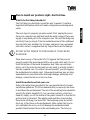
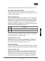
How to install our products right...the first time.
What’s the first thing I should do?
The first thing you should do is read this user’s manual. It contains
important information which will make configuration and setup much
easier.
The next step is to properly ground yourself. First, unplug the power
from your computer case and then touch the metal casing of the power
supply or any metal part on the computer case. This will discharge any
electricity from your body. Take the motherboard out of the cardboard
box and static bag, holding it by its edges, and place it on a grounded
anti-static surface, component side up. Inspect the board for damage.
DO NOT APPLY POWER TO THE BOARD IF IT HAS BEEN
DAMAGED!
Press down on any of the socket ICs if it appears that they are not
properly seated (the board should still be on an anti-static mat). Do not
touch the bottom of the board. Remember, don’t take any electronic
device out of its protective bag until you are ready to actually install it
into the computer case. If you don’t ground yourself, you risk zapping
the motherboard or adapter card. Subsequent problems may not arise
immediately because electrostatic discharge damage, unlike physical
damage, causes the device to fail over time.
Install the motherboard into your case.
Follow the instructions provided by the case manufacturer for proper
installation guidelines. TYAN recommends that you use only one screw
to hold down the motherboard. The rest of the mounting holes should be
used for the plastic standoffs. If your case does not have a hole for a
standoff, simply cut off the bottom of the plastic standoff so that the flat
portion rests on the metal. The adapter cards and the screws holding
them down will keep your board flat. The fastening screw should not
short any of the traces on the motherboard. Make certain that you do
not overtighten the screw, as it will damage the motherboard and
possibly break internal traces in the surrounding area. The hole you
!
important!
procedure
1.
2.
3.
INSTALL

http://www.tyan.com
12
Chapter 2
Board Installation
should use is located at the top-center of the board where the adapter
cards are fastened to the case.
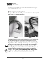
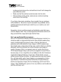
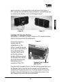
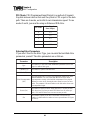
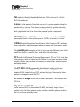
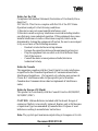
Plug in the power connector as shown.
The photos below show the ATX power connector before (Figure 1) and
after (Figure 2) it has been plugged in.
The plastic clip on the power connector should lock over the plastic tab
on the onboard connector. You shouldn’t be able to plug the power
connector in any other way but just to be safe, make sure it looks like
Figure 2 above. Make absolutely certain that you do not miss any pins
because, if you do, you will void your warranty and cause damage to
yourself or your motherboard when you turn the system on. After
connecting the power, make sure the connector is seated firmly into its
socket so it will not become loose or fall off when the computer is
jostled or moved. Note: Tyan recommends using an ATX power
supply that conforms to industry standard revision 2.01.
Figure 1
Figure 2
!
important!
warning

http://www.tyan.com
13
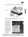
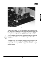
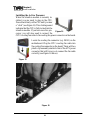
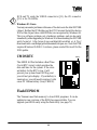
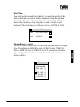
Next, connect your IDE cables (if you’re using IDE hard drives).
The colored stripe on the cable indicating pin 1 should face towards the
rear of the case (towards the ATX connectors).
In Figure 3 you can see
how the IDE cables
should look when they
are connected to your
hard drive. Notice how
Pin 1 (denoted by a red
stripe) is connected so
that it is next to the
power connector of the
drive. In most cases,
this is the proper way of
connecting your IDE
cable to the hard drive.
Figure 4 shows the IDE
cable properly con-
nected to the
motherboard.
INSTALL
Figure 3
Figure 4
Pin 1

http://www.tyan.com
14
Contact your hard disk drive manufacturer or documentation for more
information.
Some symptoms of incorrectly installed HDDs are:
• Hard disk drives are not auto-detected: may be a Master/Slave
problem or a bad IDE cable. Contact your vendor.
• Hard Disk Drive Fail message at bootup: may be a bad cable or
lack of power going to the drive.
• No video or beeps on bootup: usually means the cable is on
backwards.
• Hard drive lights are constantly on: bad IDE cable or defective
drives/motherboard. Try another HDD.
• Hard drives do not power up: check power cables and cabling.
May also be a bad power supply or IDE drive.
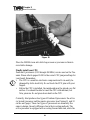
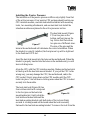
Now that you have installed your IDE drives, your floppies are next.
Pin 1 on the floppy cable is usually denoted by a red or colored stripe
down one side of the cable (see Figure 5). Most of the current floppy
drives on the market require that the colored stripe be positioned so that
it is right next to the power connector. In most cases, there will be a key
pin on the cable which will force you to connect the cable properly.
Chapter 2
Board Installation
Figure 5

http://www.tyan.com
15
Drive A: is usually attached to the end of the cable with the twist in it.
Drive B: is usually connected to the middle of the cable. Refer to your
installation instructions or call your dealer if you are unsure about
attaching floppy drives. Refer to Figure 5 on the previous page for a
detailed anatomy of the floppy cable. Remember, you can only have 2
floppy drives connected at any given time.
The colored stripe on the cable indicating pin 1 should face towards the
rear of the case (towards the ATX connectors), as with the IDE
cables. Please refer to your documentation for proper installation, or
see Figure 4 on page 13.
Some symptoms of incorrectly installed floppies are:
• Floppy drives are not detected: usually caused by faulty cables,
backward cables, or a bad floppy or motherboard. Try another
single floppy drive to verify the problem or try another cable. Also,
check to see if the onboard floppy is enabled in the BIOS.
• Floppy Drive Fail message at bootup: the cable, floppy, or
motherboard may be faulty. Try another cable or floppy drive to
verify.
• Light on the floppy is on constantly: a dead give-away that the
cable is on backwards. Reverse the cable at the motherboard end
and try again.
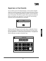
Next are the Com and Printer ports.
Warning: When plugging in your keyboard and mouse, or when
plugging anything into a serial or Com port, make sure that the power is
off. Connecting these devices and ports while the power is on is called
“hot plugging,” and may damage your system.
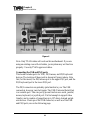
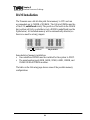
Figure 6 at the top of the next page shows the ATX double row connec-
tors on this board. The Com and Printer ports, as well as the other
ports, are labeled.
INSTALL
!
important!

http://www.tyan.com
16
Chapter 2
Board Installation
Note: Only TYAN cables will work on this motherboard. If you are
using an existing case with old cables, your system may not function
properly. Use only TYAN-approved cables.
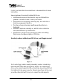
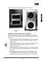
Connecting the USB and PS/2 ports.
This board includes ports for USB, PS/2 mouse, and PS/2 keyboard
devices. The location of these ports is shown in Figure 6 above. Note
that, for this board, the PS/2 mouse port is the upper PS/2 port, and the
PS/2 keyboard port is the lower PS/2 port.
The PS/2 connectors are probably quite familiar to you. The USB
connectors, however, may be foreign. The USB (Universal Serial Bus)
is a versatile port. This one port type can function as a serial, parallel,
mouse, keyboard, or joystick port. It is fast enough to support video
transfer, and is capable of supporting up to 127 daisy-chained periph-
eral devices. Close-ups of the USB connector, as well as of the USB
and PS/2 ports, are on the following page.
Figure 6

http://www.tyan.com
17
INSTALL
Figure 7 shows the USB ports and Figure 8 the PS/2 ports.
Installing your add-in cards is relatively simple but...
there are a few rules you need to follow when plugging in a card. In
order to assure proper operation and a quick installation, adhere to these
guidelines:
• If you are going to install a PCI-Bus interface card on your system,
be aware that any one of the two PCI slots can support a Master
or Slave device.
• NEVER force a card into a slot. If it doesn’t fit, look at the socket
on the computer to make sure there are no wires or other
obstructions to the slot.
• NEVER plug an ISA card into a PCI slot or a PCI card in an ISA
slot. You will void your warranty and damage your system board if
you do this.
• When plugging the card in, especially when installing long cards,
try to push the entire card in at one time. Don’t force one end of
the card into the socket first and then the other. This will create a
Figure 7 Figure 8
!
important!

http://www.tyan.com
18
Chapter 2
Board Installation
rocking motion between the card and the slot and it will damage the
pins within the socket.
• Make sure that the cards are seated securely into the slots.
• Before turning on the system, make sure no cards are touching
each other or are shorting.
If you follow these basic guidelines, there shouldn’t be any problems
with installation. However, if you do encounter any problems, have a
qualified professional install your cards for you or contact your card
manufacturer.
Remember, always read the manuals and installation notes that come
with the adapter cards. They contain important information which will
help you install the components right, the first time.
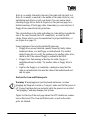
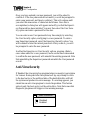
Next, you need to install your memory.
Since TYAN boards are manufactured with performance in mind, you
should use add-in components that match. Some DIMM modules may
seem to be high quality because of name or feel but that does not
guarantee real-world usability. Some cheaper or OEM memory may
have brand-name components, but they may contain inferior or substan-
dard parts which do not meet the critical tolerances our products
require. Because of this, your memory may not work correctly in a
TYAN board though it may work well in a competitor’s board. This is
because many of our competitors do not adhere to the strict tolerances
required for high performance. If you buy a TYAN board, you are
getting the best system available. To make installation easy and trouble
free, get high quality parts. Some brands we recommend are Advan-
tage Memory, Corsair Microsystems, Millenium, Kingston Memory,
QesTec Incorporated, Unigen, Micron Technology, and Crucial Tech-
nology. These DIMMs have proven to be very stable on our boards and
perform extremely well.

http://www.tyan.com
19
INSTALL
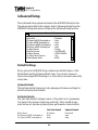
Figure 9
To install your DIMMs, line your module up so that the pins fit into the
slot. There is only one way that your DIMM can fit properly. Make sure
that the short row of pins is lined up with the short gap in the DIMM
slot. Figure 9 shows how to sit the DIMM into its slot. To insert the
DIMM, push down vertically on the module with even force, as shown
in the photo. Do not shove one end in first; doing so will bend the
DIMM pins.
To lock the DIMM into place, push the plastic clips on either end of the
slot onto the notches in the ends of the DIMM (see Figure 10 on the
next page). To remove your DIMM, simply pull the clips back, and pull
up on the module.
!
important!

http://www.tyan.com
20
Chapter 2
Board Installation
!
important!
Figure 10
Place the DIMMs in an anti-static bag as soon as you remove them to
avoid static damage.
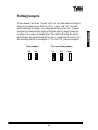
Finally, install your CPU.
Pentium II processors (233 through 450MHz) can be used on the Tsu-
nami. Please refer to pages 29-30 for the correct CPU jumper settings for
your board. Remember:
• The CPU is a sensitive electronic component and it can easily be
damaged by static electricity. Do not touch the CPU pins with your
fingers.
• Before the CPU is installed, the mainboard must be placed on a flat
surface. You should be able to insert the CPU with minimal, but
firm, pressure. Do not press down hard on the CPU.
Currently, Intel produces two types of Pentium II processors: the active
(or boxed) processor and the passive processor (see Figures 11 and 12
on the next page). These two types of processors are essentially the
same in design; the only difference lies in their cooling methods. The
active processor is equipped with a cooling fan and heat sink, while the
Page is loading ...
Page is loading ...
Page is loading ...
Page is loading ...
Page is loading ...
Page is loading ...
Page is loading ...
Page is loading ...
Page is loading ...
Page is loading ...
Page is loading ...
Page is loading ...
Page is loading ...
Page is loading ...
Page is loading ...
Page is loading ...
Page is loading ...
Page is loading ...
Page is loading ...
Page is loading ...
Page is loading ...
Page is loading ...
Page is loading ...
Page is loading ...
Page is loading ...
Page is loading ...
Page is loading ...
Page is loading ...
Page is loading ...
Page is loading ...
Page is loading ...
Page is loading ...
Page is loading ...
Page is loading ...
Page is loading ...
Page is loading ...
Page is loading ...
Page is loading ...
Page is loading ...
Page is loading ...
Page is loading ...
Page is loading ...
Page is loading ...
Page is loading ...
Page is loading ...
Page is loading ...
Page is loading ...
Page is loading ...
Page is loading ...
Page is loading ...
Page is loading ...
Page is loading ...
Page is loading ...
Page is loading ...
Page is loading ...
Page is loading ...
Page is loading ...
Page is loading ...
Page is loading ...
Page is loading ...
Page is loading ...
Page is loading ...
Page is loading ...
Page is loading ...
Page is loading ...
Page is loading ...
Page is loading ...
Page is loading ...
Page is loading ...
Page is loading ...
Page is loading ...
-
 1
1
-
 2
2
-
 3
3
-
 4
4
-
 5
5
-
 6
6
-
 7
7
-
 8
8
-
 9
9
-
 10
10
-
 11
11
-
 12
12
-
 13
13
-
 14
14
-
 15
15
-
 16
16
-
 17
17
-
 18
18
-
 19
19
-
 20
20
-
 21
21
-
 22
22
-
 23
23
-
 24
24
-
 25
25
-
 26
26
-
 27
27
-
 28
28
-
 29
29
-
 30
30
-
 31
31
-
 32
32
-
 33
33
-
 34
34
-
 35
35
-
 36
36
-
 37
37
-
 38
38
-
 39
39
-
 40
40
-
 41
41
-
 42
42
-
 43
43
-
 44
44
-
 45
45
-
 46
46
-
 47
47
-
 48
48
-
 49
49
-
 50
50
-
 51
51
-
 52
52
-
 53
53
-
 54
54
-
 55
55
-
 56
56
-
 57
57
-
 58
58
-
 59
59
-
 60
60
-
 61
61
-
 62
62
-
 63
63
-
 64
64
-
 65
65
-
 66
66
-
 67
67
-
 68
68
-
 69
69
-
 70
70
-
 71
71
-
 72
72
-
 73
73
-
 74
74
-
 75
75
-
 76
76
-
 77
77
-
 78
78
-
 79
79
-
 80
80
-
 81
81
-
 82
82
-
 83
83
-
 84
84
-
 85
85
-
 86
86
-
 87
87
-
 88
88
-
 89
89
-
 90
90
-
 91
91


Tyan S1846 Tsunami ATX User manual
- Category
- Motherboards
- Type
- User manual
- This manual is also suitable for
Ask a question and I''ll find the answer in the document
Finding information in a document is now easier with AI
Related papers
-
Tyan S1830 TSUNAMI AT User manual
-
-
-
-
Tyan Computer Tiger 100 S1832DL User manual
-
-
-
-
-
Other documents
-
Supermicro 440FX User manual
-
-
-
-
MATSONIC MS9107C User manual
-
Asus Prime Z390-A Product information
-
-
-
Acer M11E User manual
-
Gigabyte GA-5AA Owner's manual