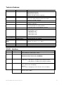
Funkwerk Bintec WI-Client Specification
- Category
- WLAN access points
- Type
- Specification
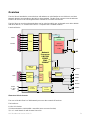
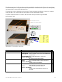
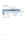
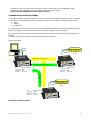
Funkwerk Bintec WI-Client is a versatile networking device that seamlessly connects devices with Ethernet or serial interfaces to wireless local area networks (WLANs) using 802.11 a/b/g standards. It features a high-speed Ethernet interface, one or two serial ports with comprehensive status lines, and a mini-PCI socket for RF card expansion. With robust security measures like WEP, WPA, and WPA2 encryption, it ensures secure data transmission.
Funkwerk Bintec WI-Client is a versatile networking device that seamlessly connects devices with Ethernet or serial interfaces to wireless local area networks (WLANs) using 802.11 a/b/g standards. It features a high-speed Ethernet interface, one or two serial ports with comprehensive status lines, and a mini-PCI socket for RF card expansion. With robust security measures like WEP, WPA, and WPA2 encryption, it ensures secure data transmission.


-
 1
1
-
 2
2
-
 3
3
-
 4
4
-
 5
5
-
 6
6
-
 7
7
-
 8
8
-
 9
9
-
 10
10
-
 11
11
-
 12
12
-
 13
13
-
 14
14
-
 15
15
-
 16
16
-
 17
17
-
 18
18
-
 19
19
-
 20
20
-
 21
21


Funkwerk Bintec WI-Client Specification
- Category
- WLAN access points
- Type
- Specification
Funkwerk Bintec WI-Client is a versatile networking device that seamlessly connects devices with Ethernet or serial interfaces to wireless local area networks (WLANs) using 802.11 a/b/g standards. It features a high-speed Ethernet interface, one or two serial ports with comprehensive status lines, and a mini-PCI socket for RF card expansion. With robust security measures like WEP, WPA, and WPA2 encryption, it ensures secure data transmission.
Ask a question and I''ll find the answer in the document
Finding information in a document is now easier with AI
Related papers
Other documents
-
Lennox L Connection Network Ethernet Converter Kit (76M77) Installation guide
-
Abocom WM3210 User manual
-
EXSYS EX-6014WI Product information
-
ELPRO 945U-E User manual
-
Silex technology SX-590 User manual
-
Digi EM1500 SERIAL TO ETHERNET User manual
-
Lancom Systems 61732 Datasheet
-
 Macsense Connectivity AeroPad Mini User manual
-
-
Hirschmann HiLCOS Reference guide
