Supermicro SUPERSERVER 6021i User manual
- Category
- Server barebones
- Type
- User manual
This manual is also suitable for

®
SUPERSERVER 6021i
USER’S MANUAL
Revision 1.0b
SUPER

The information in this User’s Manual has been carefully reviewed and is believed to be
accurate. The vendor assumes no responsibility for any inaccuracies that may be
contained in this document, makes no commitment to update or to keep current the
information in this manual, or to notify any person or organization of the updates.
Please
Note: For the most up-to-date version of this manual, please see our
web site at www.supermicro.com.
SUPERMICRO COMPUTER reserves the right to make changes to the product described in
this manual at any time and without notice. This product, including software, if any, and
documentation may not, in whole or in part, be copied, photocopied, reproduced, translated
or reduced to any medium or machine without prior written consent.
IN NO EVENT WILL SUPERMICRO COMPUTER BE LIABLE FOR DIRECT, INDIRECT,
SPECIAL, INCIDENTAL, SPECULATIVE OR CONSEQUENTIAL DAMAGES ARISING FROM
THE USE OR INABILITY TO USE THIS PRODUCT OR DOCUMENTATION, EVEN IF
ADVISED OF THE POSSIBILITY OF SUCH DAMAGES. IN PARTICULAR, THE VENDOR
SHALL NOT HAVE LIABILITY FOR ANY HARDWARE, SOFTWARE, OR DATA STORED
OR USED WITH THE PRODUCT, INCLUDING THE COSTS OF REPAIRING, REPLACING,
INTEGRATING, INSTALLING OR RECOVERING SUCH HARDWARE, SOFTWARE, OR
DATA.
Any disputes arising between manufacturer and customer shall be governed by the laws of
Santa Clara County in the State of California, USA. The State of California, County of
Santa Clara shall be the exclusive venue for the resolution of any such disputes.
Supermicro's total liability for all claims will not exceed the price paid for the hardware
product.
Unless you request and receive written permission from SUPER MICRO COMPUTER,
you may not copy any part of this document.
Information in this document is subject to change without notice. Other products and
companies referred to herein are trademarks or registered trademarks of their respective
companies or mark holders.
Copyright © 2003 by SUPER MICRO COMPUTER INC.
All rights reserved.
Printed in the United States of America.

Preface
About This Manual
This manual is written for professional system integrators and PC technicians.
It provides information for the installation and use of the SuperServer 6021i.
Installation and maintainance should be performed by experienced technicians
only.
The SuperServer 6021i is a high-end dual processor 2U rackmount server based
on the SC822 2U rackmount server chassis and the P3TDDE, a dual processor
motherboard that supports single or dual Intel Pentium
®
III FCPGA 500 MHz -
1.40 GHz processors and single or dual low power Pentium
®
III processors at
front bus speeds of 133 and 100 MHz and up to 4 GB SDRAM main memory.
CPU watchdog capability is also supported.
Manual Organization
Chapter 1: Introduction
The first chapter provides a checklist of the main components included with the
server system and describes the main features of the SUPER P3TDDE mainboard
and the SC822 chassis, which make up the SuperServer 6021i.
Chapter 2: Server Installation
This chapter describes the steps necessary to install the SuperServer 6021i
into a rack and check out the server configuration prior to powering up the
system. If your server was ordered without processor and memory com-
ponents, this chapter will refer you to the appropriate sections of the
manual for their installation.
Chapter 3: System Interface
Refer here for details on the system interface, which includes the functions
and information provided by the control panel on the chassis as well as
other LEDs located throughout the system.
iii
Preface

SUPERSERVER 6021i Manual
iv
Chapter 4: System Safety
You should thoroughly familiarize yourself with this chapter for a general overview
of safety precautions that should be followed when installing and servicing the
SuperServer 6021i.
Chapter 5: Advanced Motherboard Setup
Chapter 5 provides detailed information on the P3TDDE motherboard, includ-
ing the locations and functions of connections, headers, jumpers, DIP
switches and IRQs. Refer to this chapter when adding or removing proces-
sors or main memory and when reconfiguring the motherboard.
Chapter 6: Advanced Chassis Setup
Refer to Chapter 6 for detailed information on the SC822 2U rackmount server
chassis. You should follow the procedures given in this chapter when installing,
removing or reconfiguring SCSI or peripheral drives and when replacing system
power supply units and cooling fans.
Chapter 7: BIOS
The BIOS chapter includes an introduction to BIOS and provides detailed
information on running the CMOS Setup Utility.
Appendix A: AwardBIOS POST Messages
Appendix B: AwardBIOS POST Codes
Appendix C: AwardBIOS Error Beep Codes
Appendix D: System Specifications

v
Preface
Notes

SUPERSERVER 6021i Manual
vi
Table of Contents
Preface
About This Manual ....................................................................................................... iii
Manual Organization .................................................................................................... iii
Chapter 1: Introduction to the SuperServer 6021i
1-1 Overview ............................................................................................................ 1-1
1-2 Mainboard Features......................................................................................... 1-2
1-3 Server Chassis Features ................................................................................ 1-4
1-4 Contacting Supermicro ................................................................................... 1-6
Chapter 2: Server Installation
2-1 Overview ............................................................................................................ 2-1
2-2 Unpacking the SuperServer 6021i ................................................................. 2-1
2-3 Preparing for Setup ......................................................................................... 2-1
Choosing a Setup Location...................................................................... 2-2
Rack Precautions...................................................................................... 2-2
Server Precautions.................................................................................... 2-2
2-4 Installing the SuperServer 6021i into a Rack ............................................... 2-3
Identifying the Sections of the Rack Rails ............................................ 2-3
Installing the Chassis Rails.......................................................................2-4
Installing the Rack Rails ............................................................................2-4
Installing the Server into the Rack ...........................................................2-5
Installing the Server into a Telco Rack ....................................................2-6
2-5 Checking the Motherboard Setup .................................................................. 2-7
2-6 Checking the Drive Bay Setup....................................................................... 2-9
Chapter 3: System Interface
3-1 Overview ............................................................................................................ 3-1
3-2 Control Panel Buttons..................................................................................... 3-1
Reset.......................................................................................................... 3-1
Power ......................................................................................................... 3-1
3-3 Control Panel LEDs......................................................................................... 3-2
Overheat ..................................................................................................... 3-2
NIC2 ............................................................................................................ 3-2
NIC1 ............................................................................................................ 3-2
HDD ............................................................................................................ 3-2
Power ......................................................................................................... 3-3

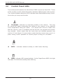
3-4 SCSI Drive Carrier LEDs................................................................................. 3-3
3-5 Motherboard LED............................................................................................. 3-3
Chapter 4: System Safety
4-1 Electrical Safety Precautions...........................................................................4-1
4-2 General Safety Precautions .............................................................................4-2
4-3 ESD Precautions ...............................................................................................4-3
4-4 Operating Precautions .....................................................................................4-3
Chapter 5: Advanced Motherboard Setup
5-1 Handling the P3TDDE Motherboard.................................................................5-1
5-2 Motherboard Installation....................................................................................5-2
5-3 Connecting Cables ............................................................................................5-3
Connecting Data Cables ............................................................................5-3
Connecting Power Cables ..........................................................................5-3
Connecting the Control Panel ...................................................................5-4
5-4 I/O Ports .............................................................................................................5-5
5-5 Installing Processors ........................................................................................5-5
5-6 Installing Memory ..............................................................................................5-8
5-7 Adding PCI Cards ..............................................................................................5-9
Super P3TDDE Layout ........................................................................... 5-11
Super P3TDDE Quick Reference .......................................................... 5-12
5-8 Connector Definitions ......................................................................................5-12
Power Supply Connectors...................................................................... 5-13
Infrared Connectorl....................................................................................5-14
Power_On Connector ................................................................................5-14
Reset Connector .......................................................................................5-14
Overheat LED .......................................................................................... 5-14
IDE RAID LED......................................................................................... 5-15
NIC LED ................................................................................................... 5-15
IDE LED ................................................................................................... 5-15
Power LED Connector ............................................................................ 5-15
PW_LED Connector................................................................................ 5-15
RAID_LED Connector ............................................................................. 5-16
Speaker Connector ...................................................................................5-16
Universal Serial Bus (USB).................................................................... 5-16
Serial Ports ............................................................................................. 5-17
Wake On LAN (WOL)............................................................................. 5-17
Wake On Ring (WOM) ........................................................................... 5-17
Fan Headers ............................................................................................ 5-17
vii
Table of Contents

SUPERSERVER 6021i Manual
viii
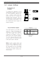
5-9 Jumper Settings...............................................................................................5-18
Explanation of Jumpers............................................................................5-18
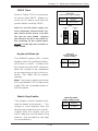
Front Side Bus Speed..............................................................................5-18
CMOS Clear ..............................................................................................5-19
Keyboard Wakeup.....................................................................................5-19
Onboard IDE RAID ....................................................................................5-20
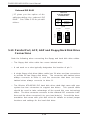
5-10 Parallel Port, ACP, AGP and Floppy/HardDisk Drive Connections ...........5-20
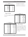
Parallel Port Connector .......................................................................... 5-21
Floppy Connector .................................................................................... 5-21
IDE Connectors ....................................................................................... 5-21
4x AGP Pro Slot..................................................................................... 5-22
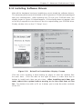
5-11 Installing Software Drivers ..............................................................................5-20
Chapter 6: Advanced Chassis Setup
6-1 Static-Sensitive Devices ................................................................................ 6-1
6-2 Control Panel .................................................................................................... 6-2
6-3 System Fans .................................................................................................... 6-3
System Fan Failure.................................................................................. 6-3
Replacing System Cooling Fans............................................................ 6-3
6-4 Drive Bay Installation/Removal ...................................................................... 6-4
Accessing the Drive Bays ..................................................................... 6-4
IDE Drive Installation................................................................................ 6-5
CD-ROM and Floppy Drive Installation ................................................. 6-7
6-5 Power Supply .................................................................................................. 6-8
Power Supply Failure ............................................................................. 6-8
Removing/Replacing the Power Supply ............................................... 6-8
Chapter 7: BIOS
7-1 Introduction....................................................................................................... 7-1
7-2 Running Setup.................................................................................................. 7-2
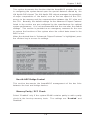
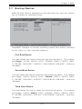
7-3 Main BIOS Setup.............................................................................................. 7-2
The Main BIOS Setup Menu .................................................................... 7-3
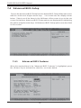
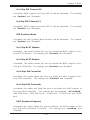
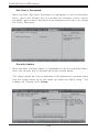
7-4 Advanced BIOS Setup.................................................................................... 7-6
Advanced BIOS Features ....................................................................... 7-6
Advanced Chipset Features................................................................... 7-8
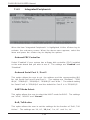
Integrated Peripherals............................................................................ 7-11
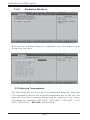
Hardware Monitors ....................................................................................7-14
Processor Features ..................................................................................7-15

Table of Contents
ix
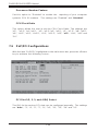
PnP/PCI Configurations............................................................................7-16
Power Management ..................................................................................7-18
Boot-up Devices ........................................................................................7-21
Security Setup ..........................................................................................7-23
Exit Setup..................................................................................................7-25
Appendices:
Appendix A: AwardBIOS POST Messages ......................................................... A-1
Appendix B: AwardBIOS POSTCodes...................................................................B-1
Appendix C: AwardBIOS Error BeepCodes ............................................................. C-1
Appendix D: System Specifications ........................................................................ D-1

Notes
SUPERSERVER 6021i User's Manual
x

Chapter 1
Introduction to the SuperServer 6021i
1-1 Overview
The Supermicro SuperServer 6021i is a high-end dual processor, 2U rackmount
server that features some of the most advanced technology currently available.
The SuperServer 6021i is comprised of two main subsystems: the SC822S-
300LP 2U rackmount chassis and the P3TDDE dual 370-pin Pentium III Tualatin
processor mainboard. Please refer to our web site for information on operating
systems that have been certified for use with the SuperServer 6021i.
(www.supermicro.com)
In addition to the mainboard and chassis, various hardware components may
have been included with your SuperServer 6021i, as listed below:
! Up to two (2) 370-pin Pentium III Tualatin processors (optional)
! Two (2) CPU heat sinks (SNK-030, optional)
! Up to 4 GB ECC registered SDRAM main memory (optional)
! One (1) 3.5" floppy drive
! One (1) slim drive bay (options: Beige CDM-001 - Black CDM-002)
! One (1) 5.25" drive bay
! One (1) 8MB 4xAGP ATI Rage XL low profile video card
! Rackmount hardware (with screws):
Two (2) rack rail assemblies
Six (6) brackets for mounting the rack rails to a rack/telco rack
! One (1) CD-ROM containing drivers and utilities:
Intel LANDesk Client Manager
ATI Rage XL 8MB PCI graphics controller driver
LAN driver
! SuperServer 6021i User's Manual
Chapter 1: Introduction
1-1

SUPERSERVER 6021i Manual
1-2
1-2 Mainboard Features
At the heart of the SuperServer 6021i lies the P3TDDE, a dual processor moth-
erboard designed to provide maximum performance. Below are the main features
of the P3TDDE.
Chipset
The P3TDDE is based on the VIA Apollo Pro 266T chipset, which is a high-
performance core logic chipset that consists of a North Bridge and a South
Bridge. See Figure 1-1 for a block diagram of the chipset.
The North Bridge includes an integrated main memory subsystem and a dual
channel PCI bus that bridges the processor bus to a 32-bit PCI bus. The
North Bridge also packs and unpacks data for PCI accesses, which re-
serves more processor bandwidth for the multiprocessor motherboard.
The South Bridge provides various integrated functions, including the PCI to
ISA bridge and support for UDMA100, security (passwords and system
protection), Plug & Play, USBs, power management, interrupt controllers
and the SMBus.
Processors
The P3TDDE supports single or dual Pentium III Tualatin 500 MHz - 1.40 GHz
processors with a 100 or 133 MHz FSB. Please refer to the support section
of our web site for a complete listing of supported processors: < http://
www.supermicro.com/TechSupport.htm >.
Memory
The P3TDDE has 4 DIMM slots that can support up to 4 GB of ECC registered
PC133 and PC100 SDRAM. Module sizes of 128MB, 256MB, 512MB and 1
GB may be used to populate the DIMM slots.
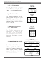
PCI Expansion Slots
The P3TDDE has five 32-bit 33 MHz PCI slots.

1-3
Chapter 1: Introduction
4xAGP Pro Slot
The P3TDDE includes a 4xAGP Pro slot, which provides for advanced video
capabilities of AGP, 2xAGP, 4xAGP, and 4xAGP Pro.
Onboard Controllers/Ports
One floppy drive controller and two onboard IDE controllers support from
one up to four hard disk drives or ATAPI devices total. The IDE RAID
controller with two EIDE RAID ports also support from one to four hard disk
drives total (please see above). Onboard I/O ports include two COM ports,
two USB ports and two USB headers, one parallel port, PS/2 mouse and
keyboard ports and one 10/100 MB Intel 82559 Ethernet (NIC) port.
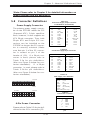
Other Features
Other onboard features that promote system health include seven voltage
monitors, two CPU temperature sensors, four fan speed sensors, a chas-
sis intrusion header, auto-switching voltage regulators, chassis and CPU
overheat sensors, BIOS virus protection and BIOS rescue.
Figure 1-1. VIA Apollo Pro 266T Chipset: System Block Diagram
VT8633
DDR Vlink
Host North
552BGA
VT8233
Vlink
133/100/66 MHz Host Bus
3D Graphics
Controller
Pentium III
FCPGA/PPGA
CPUs
PCI Slots
266 MHz
Memory
Memory Bus
AGP Bus
Clock Buffer
Clock
Generator
GCLK
MCLK
HCLK/PCLK
PCI Bus
ATA 33/66/100
MII/LAN
6x USB
LPC
SMBus
Power Plane & Peripheral Control
ACPI Events
LPC

SUPERSERVER 6021i Manual
1-4
1-3 Server Chassis Features
The SuperServer 6021i is a high-end, low-cost, scaleable 2U rackmount server
platform designed with today's most state-of-the-art features. The following is a
general outline of the main features of the SC822 chassis.
System Power
When configured as a SuperSever 6021i, the SC822 chassis includes a 300W
power supply.
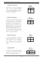
IDE Subsystem
The IDE subsystem supports two IDE channel hard drives. (Any standard 1"
drives are supported.) The IDE drives are not hot-swap units. The P3TDDE also
provides two IDE channels of IDE RAID onboard.
Control Panel
The SC822's control panel provides important system monitoring and control
information. LEDs indicate power on, network activity, hard disk drive ac-
tivity and system overheat conditions. The control panel also includes a
main power button and a system reset button.
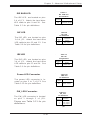
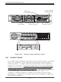
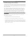
I/O Shield
The SC822 is a 2U rackmount chassis. Its I/O shield provides seven mother-
board low profile expansion slot, one COM port (the other is internal), two USB
ports, PS/2 mouse and keyboard ports, and one Ethernet port. (See Figure 1-
2.)

1-5
Chapter 1: Introduction
Cooling System
The SC822 chassis has an innovative cooling design that includes four 8-cm
redundant system cooling (intake) fans. The fans plug into chassis fan connec-
tors that located behind the HDD drive bays and operate at full rpm continuously.
If they break down, the ambient air temperature inside the chassis will rise and
activate an overheat LED.
Figure 1-2. I/O Shield
Ethernet
Ports
Mouse
Port
USB
Ports
COM2
Port
Keyboard
Port
Rear of Chassis
COM1
Port
7 Low Profile Slots
Printer
Port

SUPERSERVER 6021i Manual
1-6
1-4 Contacting Supermicro
Headquarters
Address: SuperMicro Computer, Inc.
980 Rock Ave.
San Jose, CA 95131 U.S.A.
Tel: +1 (408) 503-8000
Fax: +1 (408) 503-8008
Email: [email protected] (General Information)
[email protected] (Technical Support)
Web Site: www.supermicro.com
Europe
Address: SuperMicro Computer B.V.
Het Sterrenbeeld 28, 5215 ML
's-Hertogenbosch, The Netherlands
Tel: +31 (0) 73-6400390
Fax: +31 (0) 73-6416525
Email: [email protected] (General Information)
[email protected] (Technical Support)
[email protected] (Customer Support)
Asia-Pacific
Address: SuperMicro, Taiwan
D5, 4F, No. 16 Chien-Ba Road
Chung-Ho 235, Taipei Hsien, Taiwan, R.O.C.
Tel: +886-(2) 8226-3990
Fax: +886-(2) 8226-3991
Web Site: www.supermicro.com.tw
Technical Support:
Email: [email protected]
Tel: 886-2-8228-1366, ext.132 or 139

Chapter 2: Server Installation
2-1
Chapter 2
Server Installation
2-1 Overview
This chapter provides a quick setup checklist to get your SuperServer 6021i
up and running. Following these steps in the order given should enable you
to have the system operational within a minimum amount of time. This quick
setup assumes that your SuperServer 6021i system has come to you with
the processors and memory preinstalled. If your system is not already fully
integrated with a motherboard, processors, system memory, etc., please
turn to the chapter or section noted in each step for details on installing
specific components.
2-2 Unpacking the SuperServer 6021i
You should inspect the box the SuperServer 6021i was shipped in and note
if it was damaged in any way. If the server itself shows damage you
should file a damage claim with the carrier who delivered it.
Decide on a suitable location for the rack unit that will hold the SuperServer
6021i. It should be situated in a clean, dust-free area that is well ventilated.
Avoid areas where heat, electrical noise and electromagnetic fields are
generated. You will also need it placed near a grounded power outlet.
Read the Rack and Server Precautions in the next section.
2-3 Preparing for Setup
The box the SuperServer 6021i was shipped in should include two sets of
rail assemblies, two rail mounting brackets and the mounting screws you
will need to install the system into the rack. Follow the steps in the order
given to complete the installation process in a minimum amount of time.
Please read this section in its entirety before you begin the installation
procedure outlined in the sections that follow.

2-2
SUPERSERVER 6021i Manual
Choosing a Setup Location:
- Leave enough clearance in front of the rack to enable you to open
the chassis top cover completely (~25 inches).
- Leave approximately 30 inches of clearance in the back of the
rack to allow for sufficient airflow and ease in servicing.
Rack Precautions:
- Ensure that the leveling jacks on the bottom of the rack are fully
extended to the floor with the full weight of the rack resting on them.
- In single rack installations, stabilizers should be attached to the rack.
- In multiple rack installations, the racks should be coupled together.
- Always make certain that the rack is stable before extending a
component from the rack.
- You should extend only one component at a time - extending two
or more simultaneously may cause the rack to become unstable.
Server Precautions:
- Review the electrical and general safety precautions in Chapter 4.
- Determine the placement of each component in the rack before you
install the rails.
- Install the heaviest server components on the bottom of the rack
first, and then work upward.
- Use a regulating uninterruptible power supply (UPS) to protect the
server from power surges, voltage spikes and to keep your
system operating in case of a power failure.
- Allow the IDE drives and power supply units to cool before
touching them.
- Always keep the rack's front door and all panels and components on
the servers closed when not servicing to maintain proper cooling.
!
!
Warnings and Precautions!

Chapter 2: Server Installation
2-3
2-4 Installing the SuperServer 6021i into a Rack
This section provides information on installing the SuperServer 6021i into
a rack unit. If the 6021i has already been mounted into a rack, you can
skip ahead to Sections 2-5 and 2-6. There are a variety of rack units on
the market, which may mean the assembly procedure will differ slightly.
The following is a guideline for installing the 6021i into a rack with the
rack rails provided. You should also refer to the installation instructions
that came with the rack unit you are using.
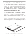
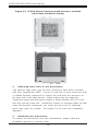
Identifying the Sections of the Rack Rails:
You should have received two rack rail assemblies with the SuperServer
6021i. Each of these assemblies consist of three sections: an inner fixed
chassis rail that secures to the 6021i (A) and an outer fixed rack rail that
secures directly to the rack itself (B). A sliding rail guide sandwiched
between the two should remain attached to the fixed rack rail. (See Figure
2-1.) The A and B rails must be detached from each other to install.
To remove the fixed chassis rail (A), pull it out as far as possible - you
should hear a "click" sound as a locking tab emerges from inside the rail
assembly and locks the inner rail. Then depress the locking tab to pull the
inner rail completely out. Do this for both the left and right side rack rail
assemblies.
Figure 2-1. Identifying the Sections of the Rack Rails
A
B

2-4
SUPERSERVER 6021i Manual
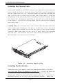
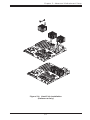
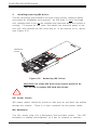
Installing the Chassis Rails:
Remove the handles on the 6021i chassis (see Figure 2-1) and position the
fixed chassis rail sections along the side of the 6021i chassis making sure
the two screw holes line up. Note that these two rails are left/right spe
cific. Slide the rails on to the hooks on both sides of the chassis. Screw the
rail securely to the side of the chassis, and then reinstall the chassis handle
(see Figure 2-2). Repeat this procedure for the other rail on the other side
of the chassis. You will also need to attach the rail brackets when installng
into a telco rack.
Locking Tabs: As you have seen, both chassis rails have a locking tab,
which serves two functions. The first is to lock the server into place
when installed and pushed fully into the rack, which is its normal position.
Secondly, these tabs also lock the server in place when fully extended
from the rack. This prevents the server from coming completely out of
the rack when you pull it out for servicing.
Figure 2-2. Installing Chassis Rails
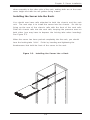
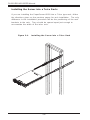
Installing the Rack Rails:
Determine where you want to place the SuperServer 6021i in the rack.
(See Rack and Server Precautions in Section 2-3.) Position the fixed rack
rail/sliding rail guide assemblies at the desired location in the rack,
keeping the sliding rail guide facing the inside of the rack. Screw the
assembly securely to the rack using the brackets provided. Attach the
Page is loading ...
Page is loading ...
Page is loading ...
Page is loading ...
Page is loading ...
Page is loading ...
Page is loading ...
Page is loading ...
Page is loading ...
Page is loading ...
Page is loading ...
Page is loading ...
Page is loading ...
Page is loading ...
Page is loading ...
Page is loading ...
Page is loading ...
Page is loading ...
Page is loading ...
Page is loading ...
Page is loading ...
Page is loading ...
Page is loading ...
Page is loading ...
Page is loading ...
Page is loading ...
Page is loading ...
Page is loading ...
Page is loading ...
Page is loading ...
Page is loading ...
Page is loading ...
Page is loading ...
Page is loading ...
Page is loading ...
Page is loading ...
Page is loading ...
Page is loading ...
Page is loading ...
Page is loading ...
Page is loading ...
Page is loading ...
Page is loading ...
Page is loading ...
Page is loading ...
Page is loading ...
Page is loading ...
Page is loading ...
Page is loading ...
Page is loading ...
Page is loading ...
Page is loading ...
Page is loading ...
Page is loading ...
Page is loading ...
Page is loading ...
Page is loading ...
Page is loading ...
Page is loading ...
Page is loading ...
Page is loading ...
Page is loading ...
Page is loading ...
Page is loading ...
Page is loading ...
Page is loading ...
Page is loading ...
Page is loading ...
Page is loading ...
Page is loading ...
Page is loading ...
Page is loading ...
Page is loading ...
Page is loading ...
Page is loading ...
Page is loading ...
Page is loading ...
Page is loading ...
Page is loading ...
Page is loading ...
Page is loading ...
Page is loading ...
Page is loading ...
Page is loading ...
Page is loading ...
Page is loading ...
Page is loading ...
Page is loading ...
Page is loading ...
Page is loading ...
-
 1
1
-
 2
2
-
 3
3
-
 4
4
-
 5
5
-
 6
6
-
 7
7
-
 8
8
-
 9
9
-
 10
10
-
 11
11
-
 12
12
-
 13
13
-
 14
14
-
 15
15
-
 16
16
-
 17
17
-
 18
18
-
 19
19
-
 20
20
-
 21
21
-
 22
22
-
 23
23
-
 24
24
-
 25
25
-
 26
26
-
 27
27
-
 28
28
-
 29
29
-
 30
30
-
 31
31
-
 32
32
-
 33
33
-
 34
34
-
 35
35
-
 36
36
-
 37
37
-
 38
38
-
 39
39
-
 40
40
-
 41
41
-
 42
42
-
 43
43
-
 44
44
-
 45
45
-
 46
46
-
 47
47
-
 48
48
-
 49
49
-
 50
50
-
 51
51
-
 52
52
-
 53
53
-
 54
54
-
 55
55
-
 56
56
-
 57
57
-
 58
58
-
 59
59
-
 60
60
-
 61
61
-
 62
62
-
 63
63
-
 64
64
-
 65
65
-
 66
66
-
 67
67
-
 68
68
-
 69
69
-
 70
70
-
 71
71
-
 72
72
-
 73
73
-
 74
74
-
 75
75
-
 76
76
-
 77
77
-
 78
78
-
 79
79
-
 80
80
-
 81
81
-
 82
82
-
 83
83
-
 84
84
-
 85
85
-
 86
86
-
 87
87
-
 88
88
-
 89
89
-
 90
90
-
 91
91
-
 92
92
-
 93
93
-
 94
94
-
 95
95
-
 96
96
-
 97
97
-
 98
98
-
 99
99
-
 100
100
-
 101
101
-
 102
102
-
 103
103
-
 104
104
-
 105
105
-
 106
106
-
 107
107
-
 108
108
-
 109
109
-
 110
110


Supermicro SUPERSERVER 6021i User manual
- Category
- Server barebones
- Type
- User manual
- This manual is also suitable for
Ask a question and I''ll find the answer in the document
Finding information in a document is now easier with AI
Related papers
-
Supermicro Supero SUPERSERVER 5013G-i User manual
-
-
-
SUPER MICRO Computer 5014C-T User manual
-
-
-
-
-
-
Other documents
-
-
-
-
 Supero SUPERSERVER 6013L-8 User manual
-
-
PC CHIPS M963GV (V5.0) User guide
-
MATSONIC MS7188D Series User manual
-
Gigabyte GS-SR113E Installation guide
-
ECS P21G (V1.0) User manual
-
 Ultra Products ULT40063 User manual

