Page is loading ...

12012 Audiovox Electronics Corporation. All rights reserved.
PROFESSIONAL
SERIES
Security and Remote Start Installation Guide
for models:
ca6153

2ca6153 revA
Before You Begin ...................................................................................... 4
Wire Connection Guide ........................................................................... 5
4 Pin Main Harness ................................................................................... 7
6 Pin Start Harness ................................................................................... 8
6 Pin Output Harness ............................................................................. 10
8 Pin Input Harness ................................................................................. 11
4 Pin Alternate Output Harness ............................................................. 14
3 Pin Door Lock Output Harness ........................................................... 15
Additional Ports ...................................................................................... 19
Antenna / LED / Programming Port ....................................................... 19
DBI Port .................................................................................................... 19
Telematic Interface Port .......................................................................... 19
Set Up & Programming .......................................................................... 20
Transmitter Programming ........................................................................ 20
Manual Feature Programming ................................................................. 20
Programming Feature Banks .................................................................. 21
Tach Programming .................................................................................. 24
Smart Tachless Mode ............................................................................. 24
Adjusting the Shock Sensor .................................................................. 25
Testing the Shock Sensor ...................................................................... 25
Chirp Delete - User Accessible .............................................................. 25
Dome Light Delay / Theater Dimming ..................................................... 25
Table of Contents

32012 Audiovox Electronics Corporation. All rights reserved.
Feature Descriptions ............................................................................. 26
Transmitter Button Functions ............................................................. 32
Security Trigger Zones ......................................................................... 33
Remote Start Shutdown Diagnostics ................................................ 33
System Layout ......................................................................................... 34

4ca6153 revA
FOR AUTOMATIC TRANSMISSION VEHICLES ONLY.
PROFESSIONAL INSTALLATION
STRONGLY RECOMMENDED
Installation Precautions:
Roll down window to avoid locking keys in vehicle
during installation
Avoid mounting components or routing wires near
hot surfaces
Avoid mounting components or routing wires near
moving parts
Tape or loom wires under hood for protection and
appearance
Technical Support (800) 421-3209
or go to
http://techservices.codesystems.com
Use a Digital Multi Meter for testing and verifying
circuits. DO NOT USE A TEST LIGHT, OR
"COMPUTER SAFE PROBE" as these can set off air
bags or damage vehicle computers.
Use grommets when routing wires through metal
surfaces
BEFORE YOU BEGIN

52012 Audiovox Electronics Corporation. All rights reserved.
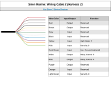
6 Pin Start Harness
4 Pin Main Harness
6 Pin Output Harness
1WHITE/RED PARKING LIGHT INPUT
2WHITE PARKING LIGHT OUTPUT
3BLACK GROUND
4BROWN SIREN OUTPUT ( + )
4 PIN MAIN
1PURPLE STARTER OUTPUT - MOTOR SIDE
2RED BATTERY 12V ( + )
3ORANGE ACCESSORY 1 ( + )
4PINK/WHITE IGNITION 2 ( + )
5RED/WHITE BATTERY 12V ( + )
6PINK IGNITION 1 ( + )
6 PIN START
1BROWN/BLACK HORN OUTPUT ( - )
2BLUE/BLACK START STATUS / ACTIVE OUTPUT ( - )
3VIOLET/BLACK AUX 1 OUTPUT ( - )
4RED/WHITE TRUNK RELEASE OUTPUT ( - )
5LT GREEN/BLACK FACTORY DISARM / PULSE BEFORE START ( - )
6ORANGE GROUND WHEN ARMED OUTPUT ( - )
6 PIN OUTPUT

6ca6153 revA
8 Pin Input Harness
3 Pin Lock Output Harness
4 Pin Alternate Output Harness
1BLUE UNLOCK ( - )
2OPEN
3GREEN LOCK ( - )
3 PIN
LOCK
1BLACK/YELLOW PULSE DURING CRANK ( - )
2GREEN/WHITE PULSE AFTER SHUTDOWN ( - )
3LT BLUE FACTORY ARM / PULSE AFTER START ( - )
4LT GREEN/BLACK FACTORY DISARM / PULSE BEFORE START ( - )
4 PIN
ALTERNATE
OUTPUT

72012 Audiovox Electronics Corporation. All rights reserved.
3 BLACK GROUND
Connect the BLACK wire to a solid chassis ground point using a ring terminal and
self tapping screw (not supplied). Scrape away paint from the grounding point to
ensure a good connection. The recommended grounding point is a metal surface
in the driver’s side kick panel area.
NOTE: Do not ground the BLACK wire with any other vehicle components.
4 Pin Main Harness
1 WHITE/RED PARKING LIGHT INPUT
2 WHITE PARKING LIGHT OUTPUT
Locate the parking light output wire at the vehicle’s light switch.
Verification: This wire registers positive voltage when the parking lights are
turned on.
Positive switching Parking Lights:
Connect the WHITE/RED wire to a 15 Amp max fused battery source.
Connect the WHITE wire to the parking light output wire.
Negative switching Parking Lights:
Connect the WHITE/RED wire to a good chassis ground.
Connect the WHITE wire to the parking light output wire.
4 BROWN SIREN OUTPUT ( + )
Locate a suitable mounting location in the engine compartment for the siren, away
from moving parts.
With the bell of the siren aiming downwards, secure the siren in place using self
tapping screws, being careful not do drill into any hoses, wiring or components.
Connect the BLACK siren wire to a chassis ground using a ring terminal and self
tapping screw (not supplied).
Route the BROWN siren output wire from the control module through the firewall
and connect to the RED wire on the siren.
NOTE: Be sure to loom the siren wires, and seal the grommet.

8ca6153 revA
3 ORANGE ACCESSORY 1 ( + )
Locate the vehicle’s accessory wire at the ignition switch.
Verification: This wire registers voltage when the key is turned to ACC
(Accessory) and the ON (or RUN) position. The voltage drops out when the
key is turned to the START (or CRANK) position.
Connect the ORANGE wire to the vehicle’s accessory wire.
6 Pin Start Harness
1 PURPLE STARTER OUTPUT ( + )
Locate the vehicle starter wire.
Verification: This wire registers voltage only when the key is turned to the
START position. Cut the vehicle's starter wire in half when installing the
starter kill relay.
Verification after starter wire is cut:
KEY SIDE of starter wire registers voltage when the key is turned to the
START position.
MOTOR SIDE of starter wire registers no voltage.
Connect the PURPLE wire to the vehicle starter wire, use the MOTOR SIDE of the vehicle
starter wire when installing the starter kill relay.
2 RED BATTERY 12V ( + )
Locate 1 of the vehicle’s constant 12 Volt battery wires at the ignition switch.
Verification: This wire will register ( + ) voltage in all positions of the ignition
switch.
Connect the RED wire to the constant 12 Volt battery wire.
NOTE: Remove all fuses until all connections are made.

92012 Audiovox Electronics Corporation. All rights reserved.
4 PINK/WHITE IGNITION 2 ( + )
Locate the vehicle’s 2nd ignition wire at the ignition switch (if equipped).
Verification: This wire registers voltage when the key is turned to the ON (or
RUN) position, but not the ACC (Accessory) position. The voltage does not
drop out when the key is turned to the START (or CRANK) position.
Connect the PINK/WHITE wire to the vehicle’s ignition 2 wire.
Programmable output: IGN, ACC, Start.
6 PINK IGNITION 1 ( + )
Locate the vehicle’s ignition wire at the ignition switch.
Verification: This wire registers voltage when the key is turned to the ON (or
RUN) position. The voltage does not drop out when the key is turned to the
START (or CRANK) position.
Connect the PINK wire to the vehicle’s Ignition wire.
This wire is also used for Ignition 1 Output.
5 RED/WHITE BATTERY 12V ( + )
Locate 1 of the vehicle’s constant 12 Volt battery wires at the ignition switch.
Verification: This wire will register ( + ) voltage in all positions of the ignition
switch.
Connect the RED/WHITE wire to the constant 12 Volt battery wire.
NOTE: Remove all fuses until all connections are made.

10 ca6153 revA
3 VIOLET/BLACK AUX 1
This wire provides a ( - ) 200mA output capable of driving relays. For Control of
optional accessories (i.e. Power Window/Sunroof, etc.).
To activate refer to the transmitter button configuration chart. Please refer to the
selectable options for timing.
4 RED/WHITE TRUNK RELEASE OUTPUT ( - )
Locate the vehicle’s trunk release wire at the trunk release switch.
Verification: This wire will register either positive voltage or ground when
the trunk release is activated.
This is a low current 200mA output and in configurable in option programming.
2 BLUE/BLACK START STATUS / ACTIVE OUTPUT ( - )
This wire provides a ground output when the remote start function is activated
and remains until 4 seconds after the remote start is shutdown. If this wire will
be used for multiple application's a 1 amp diode is required in-line with the stripe
facing the control module.
6 Pin Output Harness
1 BROWN/BLACK HORN OUTPUT ( - )
Locate the vehicle’s horn wire.
Verification: This wire will register at positive voltage and register
ground when the horn switch is pressed.
Connect the BROWN/BLACK wire to the vehicle’s horn wire. This is a low current
output, 200mA.

112012 Audiovox Electronics Corporation. All rights reserved.
8 Pin Input Harness
5 LT GREEN/BLACK FACTORY DISARM /
PULSE BEFORE START ( - )
This wire will supply a ( - ) 200mA pulse both upon disarming the system and
when the remote start feature is activated. Locate the factory perimeter alarm
disarm wire from the key cylinder inside the drivers door.
Verification: This wire registers ground if the key is turned to the unlock
position in the driver’s door cylinder.
Connect the LIGHT GREEN/BLACK wire to the factory alarm disarm wire.
6 ORANGE GROUND WHEN ARMED OUTPUT ( - )
This wire will have a continuous ( - ) 200mA output when the system is Armed. This
wire is typically used for controlling the starter interrupt relay as well as window
modules or additional sensors.
This output can be configured in option programming.
1 BLUE/WHITE INSTANT TRIGGER INPUT ( - )
This wire is a GROUND input for an external sensor or secondary pin switch.
Verification: This wire when connected will trigger the security system.
2 GREEN DOOR TRIGGER INPUT ( - )
Locate the vehicle’s dome light or door pin switch wire.
Verification: This wire will register ground (NEG) when the door is opened
and the interior light is on. This wire will register positive voltage when the
door is closed and the interior light is off.
Connect the GREEN wire to the vehicle’s negative door input wire(s).
NOTE: Certain vehicles may require multiple connections. Refer to vehicle
application guide.

12 ca6153 revA
6 BLACK/WHITE NEUTRAL SAFETY INPUT ( - )
Locate the vehicle’s neutral safety circuit.
Verification: This wire registers ( - ) voltage when the vehicle’s gear
selector is in park or neutral.
Connect the BLACK/WHITE neutral safety input wire to the neutral safety wire of
the vehicle or an optional toggle switch. The remote start feature will not operate
unless this input is supplied with a ground source.
3 PURPLE DOOR TRIGGER INPUT ( + )
Locate the vehicle’s dome light or door pin switch wire.
Verification: This wire will register positive voltage (POS) when the door is
opened and the interior light is on. This wire will
register ground or "0" Volts when the door is closed and the interior light is
off.
Connect the PURPLE wire to the vehicle’s positive door input wire(s).
NOTE: Certain vehicles may require multiple connections. Refer to vehicle
application guide.
4 WHITE/BLUE EXTERNAL START INPUT ( - )
This wire will activate the Remote Start function when a GROUND pulse is applied to it
from an external device.
5 GRAY HOOD PIN INPUT ( - )
Install a Hood Pin Switch and connect to the GRAY wire. This connection is
required for Remote Start.
Verification: This wire when connected will register ground when the
vehicle's hood is opened.
Connect the GRAY wire to the hood pin.
NOTE: Be sure to loom the wire, and seal the grommet.

132012 Audiovox Electronics Corporation. All rights reserved.
7 BROWN/RED BRAKE INPUT ( + )
Locate the vehicle’s brake light wire at the brake pedal mounted switch. This
connection is required for remote start.
Verification: This wire registers positive voltage when the brake pedal is
pressed.
Connect the BROWN/RED wire to the vehicle’s brake light wire.
8 PURPLE/WHITE TACH INPUT
Locate the vehicle’s ignition coil or fuel injector in the engine compartment.
Verification: Test using the following procedure:
1. Set voltmeter to AC VOLTS.
2. Attach positive lead of a volt meter to a constant 12 volt source.
3. Attach negative lead of a volt meter to the wire to be tested.
4. Start the engine.
5. Have someone press on the gas pedal slightly as you monitor the meter. If
connected to the correct wire, the voltage reading will increase as the
engine’s RPM increases.
Connect the PURPLE/WHITE wire to the negative side of the vehicle ignition coil or
fuel injector.

14 ca6153 revA
4 Pin Alternate Output Harness
1 LT GREEN/BLACK FACTORY DISARM /
PULSE BEFORE START ( - )
This wire will supply a ( - ) 200mA pulse both upon disarming the system and
when the remote start feature is activated. Locate the factory perimeter alarm
disarm wire from the key cylinder inside the drivers door.
Verification: This wire registers ground if the key is turned to the unlock
position in the driver’s door cylinder.
This output can be configured in option programming.
2 LT BLUE FACTORY ARM /
PULSE AFTER START ( - )
This wire will supply a ( - ) 200mA pulse both upon arming the system and upon
successful completion of the remote start activation sequence and is typically
used to re-lock the vehicle’s doors upon remote start if necessary.
This output can be configured in option programming.
4 BLACK/YELLOW PULSE DURING CRANK ( - )
Locate the vehicle’s second starter (crank) wire at the ignition switch. (if
equipped)
Verification: This wire registers voltage only in the start (crank) position of
the ignition switch.
This output can be configured in option programming.
3 GREEN/WHITE PULSE AFTER SHUTDOWN ( - )
This wire will supply a ( - ) 200mA pulse after the remote start shuts down. This
is typically used to re-lock the vehicle’s doors if they unlock upon remote start
shutdown. It can also be used to pulse a door pin-switch wire to prevent the
vehicle’s accessories from remaining on after remote start shutdown.
This output can be configured in option programming.

152012 Audiovox Electronics Corporation. All rights reserved.
3 Pin Lock Output Harness
1 BLUE UNLOCK ( - )
3 GREEN LOCK ( - )
The door lock / unlock outputs are designed to control several different types of
systems which may require additional parts. Please review the wire and location
chart to see which type of door lock system is in your vehicle. The most common
types are shown in the following diagrams.
Negative Switching Locks
All Door Lock and Unlock: Locate the lock / unlock wire at the vehicle’s lock /
unlock switch.
Verification: These wires will register ground when the Lock and Unlock
switches are activated.
Connect the GREEN and BLUE wires shown in the diagram below.
Lock
Unlock
Vehicle Door Lock
Control Relays
GREEN (-) Lock Output
BLUE (-) Unlock Output
Negative Locks:

16 ca6153 revA
Positive Switching Locks
All Door Lock and Unlock: Locate the lock / unlock wire at the vehicle’s lock /
unlock switch.
Verification: These wires will register positive voltage when the Lock and
Unlock switches are activated.
Connect the GREEN and BLUE wires shown in the diagram below.
Lock
Unlock
87
87a
86 85
30
87
87a
86 85
30
Vehicle Door Lock
Control Relays
Fused +12 Volt
Battery Souce
Fused +12 Volt
Battery Souce
GREEN (-) Lock Output
BLUE (-) Unlock Output
P
os
i
t
i
ve
L
oc
k
s:
Reverse Polarity Locks (5-Wire Door locks)
All Door Lock and Unlock: Locate the lock / unlock wire at the vehicle’s lock /
unlock switch.
Verification: These wires will rest at ground and register positive
voltage when the Lock and Unlock switches are activated.
Connect the GREEN and BLUE or BLUE/GREEN wires shown in the diagram
below using (2) SPDT relays (not supplied).
Lock
Unlock
87
87a
86 85
30
87
87a
86 85
30
Fused +12 Volt
Battery Souce
Fused +12 Volt
Battery Souce
GREEN (-) Lock Output
BLUE (-) Unlock Output
Reverse Polarity Locks:
X
Cut
X
Cut
To Door Lock Motor
To Door Lock Motor

172012 Audiovox Electronics Corporation. All rights reserved.
Negative Multiplexed Locks
All Door Lock and Unlock: Locate the lock / unlock wire at the vehicle’s lock /
unlock switch.
Verification: This wire will show variable ground when the switch is activated.
Please consult the wire and location chart for specific resistor values for
your vehicle.
Connect the GREEN and BLUE or BLUE/GREEN wires shown in the diagram
below using (2) SPDT relays (not supplied).
Lock
Unlock
Vehicle Door Lock
Control Relays
GREEN (-) Lock Output BLUE (-) Unlock Output
Multiplex Locks:
87
87a
86
30
87
87a
86
30
85 85
Fused +12 Volt
Battery Source
Ground
Resistor
Positive Multiplexed Locks
All Door Lock and Unlock: Locate the lock / unlock wire at the vehicle’s lock /
unlock switch.
Verification: This wire will show variable positive voltage when the switch is
activated. Please consult the wire and location chart for specific resistor
values for your vehicle.
Connect the GREEN and BLUE or BLUE/GREEN wires shown in the diagram
below using (2) SPDT relays (not supplied).
Lock
Unlock
Vehicle Door Lock
Control Relays
GREEN (-) Lock Output BLUE (-) Unlock Output
Multiplex Locks:
87
87a
86
30
87
87a
86
30
85 85
Fused +12 Volt
Battery Source
Resistor

18 ca6153 revA
Adding Aftermarket Actuators
After installing aftermarket actuators, (not supplied). Connect the GREEN and
BLUE wires shown in the diagram below using (2) SPDT relays (not supplied).
30
87
87a
86 85
Fused +12 Volt
Battery Source
Door Lock
Actuator
30
87
87a
86 85
Chassis
Ground
Chassis
Ground
GREEN (-) Lock Output
BLUE (-) Unlock Output
Fused +12 Volt
Battery Source
M

192012 Audiovox Electronics Corporation. All rights reserved.
Data Bus Interface Port
This 4 pin port is used for Flashlogic Door Lock and Transponder Databus
Interfaces to communicate with the vehicle's Databus. When using the DBI port to
control the Flashlogic Door Lock and Transponder Interface modules the
following options may be available. Please refer to the D2D (Data to Data)
function list available per vehicle on the tech service web site.
Tach Input Brake Safety Shut Down
Door Trigger Trunk/Hatch Open
Door Lock Control Passlock / Passkey Interface (GM Only)
Dome Light Supervision Transponder Interface Activation
Factory Alarm Arm / Disarm Diesel Glow Plug Input
Manual Arm / Disarm Inputs (factory keyless controls system)
Antenna / LED / Programming Port
Mount the supplied antenna/receiver to a clear spot on the vehicle's windshield
that will not block the driver's vision. A good location is usually high on the
windshield near the rear view mirror. Be careful not to mount the antenna/receiver
on any metallic window film, as this will effect system range. Route the antenna/
receiver cable to the control module and plug into the antenna port.
Additional Ports
Telematic Interface Port
This 4 pin port is used for telematic Interface accessories, such as the CarLink
ASCL1, which can control some of the following features.
Door Lock Control Trunk Release
Sliding Doors AUX Output
Car Find Remote Start

20 ca6153 revA
Manual Feature Programming - Feature Bank 2 - 5
1. Turn the ignition ON.
2. Press and hold the valet/override button.
3. Within 10 seconds the system will chirp (3) three times.
4. Use the valet/override button to advance through each option bank. For
feature programming advance to Feature Bank 2, 3, 4 or 5, which is (4)
four, (5) five, (6) six and (7) seven chirps.
5. Use the transmitter button to scroll through the selections in each
feature bank, the system will chirp to match the feature number.
6. Press the transmitter button to change the desired feature. The LED will
flash indicating the changed feature.
Set Up & Programming
Transmitter Programming - Feature Bank 1
1. Turn the ignition ON.
2. Press and hold the valet/override button.
3. Within 10 seconds the system will chirp (3) three times.
4. Press 1 button of each transmitter you wish to program.
5. The system will respond with 1 chirp for each accepted transmitter.
6. Pressing the override button at anytime during programming will advance to
the next bank.
NOTE: The system will exit transmitter programming after 15 seconds of inactivity.
NOTE: This system has 1 button programming which programs all channels of the
system.
NOTE: The system will hold up to 4 transmitters in memory, programming a 5th
transmitter will erase the oldest transmitter in memory.
NOTE: This system has PTN - Programmed Transmitter Notification. Each time the
ignition is turned ON, the LED will flash the number of transmitters programmed to
the system.
Transmitter programming for 2 Car Mode *2 way system only:
1. Enter the transmitter into 2 Car Mode. (Refer to transmitter operation in the
owners manual for 2 car operation)
2. Follow the steps above for transmitter programming.
NOTE: 2 car mode requires an additional security system installed in a second
vehicle.
/