Page is loading ...

Z97-P
Motherboard

ii
E9385
First Edition
May 2014
Copyright © 2014 ASUSTeK COMPUTER INC. All Rights Reserved.
No part of this manual, including the products and software described in it, may be reproduced,
transmitted, transcribed, stored in a retrieval system, or translated into any language in any form or by any
means, except documentation kept by the purchaser for backup purposes, without the express written
permission of ASUSTeK COMPUTER INC. (“ASUS”).
Product warranty or service will not be extended if: (1) the product is repaired, modied or altered, unless
such repair, modication of alteration is authorized in writing by ASUS; or (2) the serial number of the
product is defaced or missing.
ASUS PROVIDES THIS MANUAL “AS IS” WITHOUT WARRANTY OF ANY KIND, EITHER EXPRESS
OR IMPLIED, INCLUDING BUT NOT LIMITED TO THE IMPLIED WARRANTIES OR CONDITIONS OF
MERCHANTABILITY OR FITNESS FOR A PARTICULAR PURPOSE. IN NO EVENT SHALL ASUS, ITS
DIRECTORS, OFFICERS, EMPLOYEES OR AGENTS BE LIABLE FOR ANY INDIRECT, SPECIAL,
INCIDENTAL, OR CONSEQUENTIAL DAMAGES (INCLUDING DAMAGES FOR LOSS OF PROFITS,
LOSS OF BUSINESS, LOSS OF USE OR DATA, INTERRUPTION OF BUSINESS AND THE LIKE),
EVEN IF ASUS HAS BEEN ADVISED OF THE POSSIBILITY OF SUCH DAMAGES ARISING FROM ANY
DEFECT OR ERROR IN THIS MANUAL OR PRODUCT.
SPECIFICATIONS AND INFORMATION CONTAINED IN THIS MANUAL ARE FURNISHED FOR
INFORMATIONAL USE ONLY, AND ARE SUBJECT TO CHANGE AT ANY TIME WITHOUT NOTICE,
AND SHOULD NOT BE CONSTRUED AS A COMMITMENT BY ASUS. ASUS ASSUMES NO
RESPONSIBILITY OR LIABILITY FOR ANY ERRORS OR INACCURACIES THAT MAY APPEAR IN THIS
MANUAL, INCLUDING THE PRODUCTS AND SOFTWARE DESCRIBED IN IT.
Products and corporate names appearing in this manual may or may not be registered trademarks or
copyrights of their respective companies, and are used only for identication or explanation and to the
owners’ benet, without intent to infringe.
Offer to Provide Source Code of Certain Software
This product contains copyrighted software that is licensed under the General Public License (“GPL”),
under the Lesser General Public License Version (“LGPL”) and/or other Free Open Source Software
Licenses. Such software in this product is distributed without any warranty to the extent permitted by the
applicable law. Copies of these licenses are included in this product.
Where the applicable license entitles you to the source code of such software and/or other additional data,
you may obtain it for a period of three years after our last shipment of the product, either
(1) for free by downloading it from http://support.asus.com/download
or
(2) for the cost of reproduction and shipment, which is dependent on the preferred carrier and the location
where you want to have it shipped to, by sending a request to:
ASUSTeK Computer Inc.
Legal Compliance Dept.
15 Li Te Rd.,
Beitou, Taipei 112
Taiwan
In your request please provide the name, model number and version, as stated in the About Box of the
product for which you wish to obtain the corresponding source code and your contact details so that we
can coordinate the terms and cost of shipment with you.
The source code will be distributed WITHOUT ANY WARRANTY and licensed under the same license as
the corresponding binary/object code.
This offer is valid to anyone in receipt of this information.
ASUSTeK is eager to duly provide complete source code as required under various Free Open Source
Software licenses. If however you encounter any problems in obtaining the full corresponding source
code we would be much obliged if you give us a notication to the email address [email protected], stating
the product and describing the problem (please DO NOT send large attachments such as source code
archives, etc. to this email address).
ii

iii
Contents
Safety information ...................................................................................... iv
About this guide ......................................................................................... iv
Package contents ....................................................................................... vi
Z97-P specifications summary .................................................................. vi
Chapter 1: Product introduction
1.1 Before you proceed ..................................................................... 1-1
1.2 Motherboard overview ................................................................. 1-2
1.3 Central Processing Unit (CPU) ................................................... 1-4
1.4 System memory ........................................................................... 1-8
1.5 Expansion slots .......................................................................... 1-10
1.6 Jumpers ...................................................................................... 1-12
1.7 Connectors ................................................................................. 1-13
1.8 Software support ........................................................................ 1-22
Chapter 2: BIOS information
2.1 Managing and updating your BIOS ............................................ 2-1
2.2 BIOS setup program .................................................................... 2-6
2.3 My Favorites ............................................................................... 2-15
2.4 Main menu .................................................................................. 2-17
2.5 Ai Tweaker menu ........................................................................ 2-19
2.6 Advanced menu ......................................................................... 2-30
2.7 Monitor menu ............................................................................. 2-40
2.8 Boot menu .................................................................................. 2-43
2.9 Tool menu ................................................................................... 2-49
2.10 Exit menu .................................................................................... 2-50
Appendices
Notices .......................................................................................................A-1
ASUS contact information .......................................................................A-3
iii

Safety information
Electrical safety
• To prevent electrical shock hazard, disconnect the power cable from the electrical outlet
before relocating the system.
• When adding or removing devices to or from the system, ensure that the power cables
for the devices are unplugged before the signal cables are connected. If possible,
disconnect all power cables from the existing system before you add a device.
• Before connecting or removing signal cables from the motherboard, ensure that all
power cables are unplugged.
• Seek professional assistance before using an adapter or extension cord. These devices
could interrupt the grounding circuit.
• Ensure that your power supply is set to the correct voltage in your area. If you are not
sure about the voltage of the electrical outlet you are using, contact your local power
company.
• If the power supply is broken, do not try to x it by yourself. Contact a qualied service
technician or your retailer.
Operation safety
• Before installing the motherboard and adding components, carefully read all the manuals
that came with the package.
• Before using the product, ensure all cables are correctly connected and the power
cables are not damaged. If you detect any damage, contact your dealer immediately.
• To avoid short circuits, keep paper clips, screws, and staples away from connectors,
slots, sockets and circuitry.
• Avoid dust, humidity, and temperature extremes. Do not place the product in any area
where it may be exposed to moisture.
• Place the product on a stable surface.
• If you encounter technical problems with the product, contact a qualied service
technician or your retailer.
About this guide
This user guide contains the information you need when installing and conguring the
motherboard.
How this guide is organized
This guide contains the following parts:
• Chapter1:Productintroduction
This chapter describes the features of the motherboard and the new technology it
supports. It includes descriptions of the switches, jumpers, and connectors on the
motherboard.
• Chapter2:BIOSinformation
This chapter discusses changing system settings through the BIOS Setup menus.
Detailed descriptions for the BIOS parameters are also provided.
iv

Where to find more information
Refer to the following sources for additional information and for product and software
updates.
1. ASUS websites
The ASUS website provides updated information on ASUS hardware and software
products. Refer to the ASUS contact information.
2. Optional documentation
Your product package may include optional documentation, such as warranty yers,
that may have been added by your dealer. These documents are not part of the
standard package.
Conventions used in this guide
To ensure that you perform certain tasks properly, take note of the following symbols used
throughout this manual.
DANGER/WARNING: Information to prevent injury to yourself when
completing a task.
CAUTION: Information to prevent damage to the components when
completing a task
IMPORTANT: Instructions that you MUST follow to complete a
task.
NOTE: Tips and additional information to help you complete a task.
Typography
Bold text Indicates a menu or an item to select.
Italics
Used to emphasize a word or a phrase.
<Key> Keys enclosed in the less-than and greater-than sign
means that you must press the enclosed key.
Example: <Enter> means that you must press the Enter or
Return key.
<Key1> + <Key2> + <Key3> If you must press two or more keys simultaneously, the key
names are linked with a plus sign (+).
v

Z97-P specifications summary
(continued on the next page)
CPU LGA1150 socket for the 4th Generation, New 4th Generation and 5th
Generation Intel® Core™ i7 / Core™ i5 / Core™ i3, Pentium®, and
Celeron® processors
Supports 22nm CPU
Supports Intel® Turbo Boost Technology 2.0*
* The Intel® Turbo Boost Technology 2.0 support depends on the CPU types.
** Refer to www.asus.com for Intel® CPU support list.
Chipset Intel® Z97 Express Chipset
Memory 4 x DIMM, max. 32GB, DDR3 3200(O.C.)*/3100(O.C.)*/3000(O.C.)*/
2933(O.C.)*/2800(O.C.)*/2666(O.C.)*/2600(O.C.)*/2400(O.C.)*/ 2250(O.
C.)*/2200(O.C.)*/2133(O.C.)*/2000(O.C.)*/ 1866(O.C.)*/ 1600/1333
MHz, non-ECC, un-buffered memory
Dual-channel memory architecture
Supports Intel® Extreme Memory Prole (XMP)
* Hyper DIMM support is subject to the physical characteristics of individual
CPUs. Please refer to Memory QVL (Qualified Vendors List) for details.
** Refer to www.asus.com for the Memory QVL (Qualified Vendors List).
Expansion slots 1 x PCI Express 3.0/2.0 x16 slot (at x16 mode)
1 x PCI Express 2.0 x16 slot (max at x2 mode)
2 x PCI Express 2.0 x1 slots
2 x PCI slots
Package contents
Check your motherboard package for the following items.
Motherboard ASUS Z97-P motherboard
Cables 2 x Serial ATA 6.0 Gb/s cables
Accessories 1 x I/O Shield
Application DVD Support DVD
Documentation User Guide
If any of the above items is damaged or missing, contact your retailer.
vi

Z97-P specifications summary
Graphics Integrated Graphics Processor - Intel® HD Graphics support
Multi-VGA output support: HDMI, DVI-D, RGB port
Supports HDMI with max. resolution of 4096 x 2160 @24Hz / 2560 x 1600
@60Hz
Supports DVI-D with max. resolution of 1920 x 1200 @60Hz
Supports RGB with max. resolution of 1920 x 1200 @60Hz
Supports Intel® InTru™ 3D, Intel® Quick Sync Video, Intel® Clear Video HD
Technology, and Intel® Insider™
Supports up to three displays simultaneously
Maximum shared memory 512MB
Storage Intel® Z97 Express Chipset with RAID 0, 1, 5, 10 and Intel®
Rapid Storage Technology 13 support
- 1 x M.2 Socket 3 with M Key, type 2260/2280 storage devices
support (both SATA & PCIE mode)
- 4 x SATA 6.0 Gb/s ports (gray)
- Supports Intel® Smart Response Technology, Intel® Rapid Start
Technology, and Intel® Smart Connect Technology**
* These functions will work depending on the CPU installed.
LAN Realtek® 8111GR Gigabit LAN controller
Audio Realtek® ALC891 7.1-channel high denition audio CODEC featuring
audio features
- Audio Shielding: Ensures precision analog/digital separation and
greatly reduced multi-lateral interference
- Dedicated audio PCB layers: Separate layers for left and right
channels to guard the quality of the sensitive audio signals
- Audio amplier: Provides the highest-quality sound for headphone
and speakers
- Unique de-pop circuit: Reduces start-up popping noise to audio
outputs
- Supports jack-detection and front panel jack-retasking
USB Intel® Z97 Express Chipset - supports ASUS USB 3.0 Boost
- 6 x USB 3.0/2.0 ports (2 ports at mid-board; 4 ports at rear panel,
blue)
- 8 x USB 2.0/1.1 ports (6 ports at mid-board; 2 ports at rear panel)
(continued on the next page)
vii

Z97-P specifications summary
ASUS special
features
High Performance
ASUS 5X PROTECTION
- ASUS DIGI+ VRM - 4 Phase digital power design
- ASUS Enhanced DRAM Overcurrent Protection - Short circuit
damage prevention
- ASUS ESD Guards - Enhanced ESD protection
- ASUS High-Quality 5K-Hour Solid Capacitors - 2.5x long lifespan
with excellent durability
- ASUS Stainless Steel Back I/O - 3x more durable corrosion-resistant
coatin
UEFI BIOS
- Most advanced options with fast response time
M.2 onboard
- The latest transfer technologies with up to 10 Gb/s data transfer
speeds
ASUS Fan Xpert 2+
- Ultimate cooling and quietness
ASUS EPU
- EPU
Interactive HomeCloud
Media Streamer
- Pipe music or movies from your PC to a smart TV
- Media Streamer app for portable smartphone/tablet, supporting
iOS 7 and Android 4.0 system
Gaming Scenario
Steam support
- Compatible with the most fun gaming platform under Windows®
system
ASUS Exclusive Features
- GPU Boost
- USB 3.0 Boost
- Ai Charger
- AI Suite 3
- Disk Unlocker
EZ DIY
Push Notice
- Monitor your PC status with smart devices in real time
UEFI BIOS EZ Mode
- featuring friendly graphics user interface
- ASUS O.C. Tuner
- ASUS CrashFree BIOS 3
- ASUS EZ Flash 2
Q-Design
- ASUS Q-Slot
(continued on the next page)
viii

Z97-P specifications summary
ASUS quiet thermal
solution
Quiet Thermal Design
- ASUS Fan Xpert 2+
- Stylish Fanless Design: PCH Heat-sink & MOS Heat-sink solution
ASUS exclusive
overclocking features Precision Tweaker 2
- vCore: Adjustable CPU Core voltage at 0.001V increment
- iGPU: Adjustable CPU Graphics voltage at 0.001V increment
- vCCIO: Adjustable Analog and Digital I/O voltage at 0.001V
increment
- vCCIN: Adjustable CPU Input voltage at 0.01V increment
- vCCSA: Adjustable CPU System Agent voltage at 0.001V increment
- vDRAM Bus: 124-step Memory voltage control
- vPCH: 154-step Chipset voltage control
SFS (Stepless Frequency Selection)
- BCLK/PCIE frequency tuning from 80MHz up to 300MHz at 0.1MHz
increment
Overclocking Protection
- ASUS C.P.R.(CPU Parameter Recall)
Rear panel I/O ports 1 x PS/2 keyboard port
1 x PS/2 mouse port
1 x HDMI port
1 x DVI-D port
1 x RGB port
1 x LAN (RJ-45) port
4 x USB 3.0/2.0 ports (blue)
2 x USB 2.0/1.1 ports
3-jack 7.1-channel audio I/O ports
Internal connectors 1 x 19-pin USB 3.0/2.0 connector supports additional 2 USB ports
3 x USB 2.0/1.1 connectors support additional 6 USB ports
1 x M.2 Socket 3 (for M Key, type 2260/2280 devices)
4 x SATA 6.0 Gb/s connectors (gray)
1 x 4-pin CPU Fan connector for (PWM mode)
2 x 4-pin Chassis Fan connectors for both 3-pin (DC mode) and 4-pin
(PWM mode) coolers control
1 x Front panel audio connector (AAFP)
1 x System panel connector
1 x S/PDIF out header
1 x 24-pin EATX Power connector
1 x 8-pin EATX 12V Power connector
1 x COM connector
1 x TPM connector
1 x Clear CMOS jumper
(continued on the next page)
ix

BIOS features 64 Mb Flash ROM, UEFI AMI BIOS, PnP, DMI 2.7, WfM 2.0, SM BIOS
2.8.0, ACPI 5.0, Multi-language BIOS, ASUS EZ Flash 2, CrashFree BIOS
3, F11 EZ Tuning Wizard, F6 Qfan Control, F3 My Favorites, Quick Note,
Last Modied Log, F12 PrintScreen function, F3 Shortcut function, and
ASUS DRAM SPD (Serial Presence Detect) memory information
Manageability WfM 2.0, DMI 2.7, WOR by PME, PXE
Support DVD Drivers
ASUS utilities
EZ Update
Anti-virus software (OEM version)
OS support Windows® 8.1, 32-bit/64-bit
Windows® 8, 32-bit/64-bit
Windows® 7, 32-bit/64-bit
Form factor ATX form factor: 12.0 in. x 8.4 in. (30.5 cm x 21.3 cm)
Z97-P specifications summary
Specications are subject to change without notice.
x

ASUS Z97-P 1-1
Product introduction
1
1.1 Before you proceed
Take note of the following precautions before you install motherboard components or change
any motherboard settings.
• Unplugthepowercordfromthewallsocketbeforetouchinganycomponent.
• Beforehandlingcomponents,useagroundedwriststraportouchasafelygrounded
objectorametalobject,suchasthepowersupplycase,toavoiddamagingthemdue
to static electricity.
• HoldcomponentsbytheedgestoavoidtouchingtheICsonthem.
• Wheneveryouuninstallanycomponent,placeitonagroundedantistaticpadorinthe
bag that came with the component.
• Beforeyouinstallorremoveanycomponent,ensurethattheATXpowersupplyis
switched off or the power cord is detached from the power supply. Failure to do so
maycauseseveredamagetothemotherboard,peripherals,orcomponents.

1-2 Chapter 1: Product introduction
1.2 Motherboard overview
Beforeyouinstallthemotherboard,studythecongurationofyourchassistoensurethatthe
motherboardts.
Unplugthepowercordbeforeinstallingorremovingthemotherboard.Failuretodosocan
cause you physical injury and damage to motherboard components.
1.2.1 Placement direction
Wheninstallingthemotherboard,placeitintothechassisinthecorrectorientation.Theedge
with external ports goes to the rear part of the chassis as indicated in the image.
1.2.2 Screw holes
Place six screws into the holes indicated by circles to secure the motherboard to the chassis.
Donotovertightenthescrews!Doingsocandamagethemotherboard.
Place this side
towards the rear
of the chassis
Z97-P

ASUS Z97-P 1-3
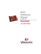
1.2.3 Motherboard layout
Z97-P
PCIEX16_1
PCIEX16_2
PCIEX1_1
PCIEX1_2
ASM
1083
PCI1
PCI2
USB910 USB1112 USB1314
AAFP
EATXPWR
CPU_FAN CHA_FAN2
BATTERY
Super
I/O
ALC
891
RTL
8111GR
ASM
1442K
KBMS
DVI_VGA
CLRTC
21.3cm(8.4in)
Intel®
Z97
DDR3 DIMM_A1 (64bit, 240-pin module)
DDR3 DIMM_A2 (64bit, 240-pin module)
DDR3 DIMM_B1 (64bit, 240-pin module)
DDR3 DIMM_B2 (64bit, 240-pin module)
SATA6G_3SATA6G_4
SPEAKER
SATA6G_1SATA6G_2
AUDIO
LAN_USB78
USB3_56
USB3_34
HDMI
CHA_FAN1
SPDIF_OUT
30.5cm(12.0in)
LGA1150
DIGI
+VRM
COM
EATX12V
USB3_12
TPM
M.2(SOCKET3)
64Mb
BIOS
F_PANEL
2 31 41
1015 911 5121314
2
5
8
6
7

1-4 Chapter 1: Product introduction
1.2.4 Layout contents
1.3 Central Processing Unit (CPU)
ThismotherboardcomeswithasurfacemountLGA1150socketdesignedforthe4th
Generation,New4thGenerationand5thGenerationIntel®Core™i7/Core™i5/Core™i3,
Pentium® ,Celeron® processors.
UnplugallpowercablesbeforeinstallingtheCPU.
Connectors/Jumpers/Slots/LED Page
1. CPUandchassisfanconnectors(4-pinCPU_FAN,4-pinCHA_FAN1/2) 1-15
2. ATXpowerconnectors(24-pinEATXPWR,8-pinEATX12V) 1-18
3. LGA1150CPUsocket 1-4
4. DDR3DIMMslots 1-8
5. Intel®Z97SerialATA6.0Gb/sconnectors(7-pinSATA6G_1-4) 1-16
6. USB3.0connector(20-1pinUSB3_12) 1-21
7. M.2Socket3 1-21
8. Speakerconnector(4-pinSPEAKER) 1-18
9. Systempanelconnector(10-1pinF_PANEL) 1-20
10. ClearRTCRAM(3-pinCLRTC) 1-12
11. USB2.0connectors(10-1pinUSB910,USB1112,USB1314) 1-19
12. TPMconnector(20-1pinTPM) 1-19
13. Serialportconnector(10-1pinCOM) 1-15
14. Digitalaudioconnector(4-1pinSPDIF_OUT) 1-17
15. Frontpanelaudioconnector(10-1pinAAFP) 1-17
Z97-P
Z97-P CPU socket LGA1150

ASUS Z97-P 1-5
1.3.1 Installing the CPU
1
23
A
B
• Uponpurchaseofthemotherboard,ensurethatthePnPcapisonthesocketand
thesocketcontactsarenotbent.ContactyourretailerimmediatelyifthePnPcap
ismissing,orifyouseeanydamagetothePnPcap/socketcontacts/motherboard
components.ASUSwillshoulderthecostofrepaironlyifthedamageisshipment/
transit-related.
• Keepthecapafterinstallingthemotherboard.ASUSwillprocessReturnMerchandise
Authorization(RMA)requestsonlyifthemotherboardcomeswiththecaponthe
LGA1150socket.
• Theproductwarrantydoesnotcoverdamagetothesocketcontactsresultingfrom
incorrectCPUinstallation/removal,ormisplacement/loss/incorrectremovalofthePnP
cap.

1-6 Chapter 1: Product introduction
A
B
C
5
4
1.3.2 CPU heatsink and fan assembly installation
ApplytheThermalInterfaceMaterial
totheCPUheatsinkandCPU
before you install the heatsink and
fan if necessary.

ASUS Z97-P 1-7
3 4
A
B
B
A
To uninstall the CPU heatsink and fan assembly
2
1
To install the CPU heatsink and fan assembly
2
B
A
A
B
1

1-8 Chapter 1: Product introduction
1.4 System memory
1.4.1 Overview
ThismotherboardcomeswithfourDoubleDataRate3(DDR3)DualInlineMemoryModule
(DIMM)sockets.ThegureillustratesthelocationoftheDDR3DIMMsockets:
Channel Sockets
ChannelA DIMM_A1andDIMM_A2
ChannelB DIMM_B1andDIMM_B2
1.4.2 Memory configurations
Youmayinstall2GB,4GB,and8GBunbufferednon-ECCDDR3DIMMsintotheDIMM
sockets.
• YoumayinstallvaryingmemorysizesinChannelAandChannelB.Thesystem
mapsthetotalsizeofthelower-sizedchannelforthedual-channelconguration.Any
excessmemoryfromthehigher-sizedchannelisthenmappedforsingle-channel
operation.
• AccordingtoIntelCPUspec,DIMMvoltagebelow1.65Visrecommendedtoprotect
theCPU.
• AlwaysinstallDIMMswiththesameCASlatency.Foroptimalcompatibility,we
recommendthatyouinstallmemorymodulesofthesameversionordatecode(D/C)
fromthesamevendor.Checkwiththeretailertogetthecorrectmemorymodules.
• Duetothememoryaddresslimitationon32-bitWindows®OS,whenyouinstall4GB
ormorememoryonthemotherboard,theactualusablememoryfortheOScanbe
about3GBorless.Foreffectiveuseofmemory,werecommendthatyoudoanyofthe
following:
- Useamaximumof3GBsystemmemoryifyouareusinga32-bitWindows®OS.
- Installa64-bitWindows®OSifyouwanttoinstall4GBormoreonthe
motherboard.
- Formoredetails,refertotheMicrosoft® support site at http://support.microsoft.
com/kb/929605/en-us.
• ThismotherboarddoesnotsupportDIMMsmadeupof512megabits(Mb)chipsor
less.
• ThedefaultmemoryoperationfrequencyisdependentonitsSerialPresenceDetect
(SPD),whichisthestandardwayofaccessinginformationfromamemorymodule.
Underthedefaultstate,somememorymodulesforoverclockingmayoperateata
lowerfrequencythanthevendor-markedvalue.Tooperateatthevendor-marked
oratahigherfrequency,refertosection2.5 Ai Tweaker menu for manual memory
frequencyadjustment.
• Forsystemstability,useamoreefcientmemorycoolingsystemtosupportafull
memoryload(4DIMMs)oroverclockingcondition.
• VisittheASUSwebsiteat:www.asus.comforthelatestQVL.
Z97-P
Z97-P
240-pin DDR3 DIMM sockets
DIMM_A1
DIMM_A2
DIMM_B1
DIMM_B2

ASUS Z97-P 1-9
1.4.3 Installing a DIMM
To install a DIMM
1
2
3
To remove a DIMM
B
A
A

1-10 Chapter 1: Product introduction
1.5 Expansion slots
Inthefuture,youmayneedtoinstallexpansioncards.Thefollowingsub-sectionsdescribe
the slots and the expansion cards that they support.
Unplugthepowercordbeforeaddingorremovingexpansioncards.Failuretodosomay
cause you physical injury and damage motherboard components.
1.5.1 Installing an expansion card
To install an expansion card:
1. Beforeinstallingtheexpansioncard,readthedocumentationthatcamewithitand
make the necessary hardware settings for the card.
2. Removethesystemunitcover(ifyourmotherboardisalreadyinstalledinachassis).
3. Removethebracketoppositetheslotthatyouintendtouse.Keepthescrewforlater
use.
4. Alignthecardconnectorwiththeslotandpressrmlyuntilthecardiscompletely
seated on the slot.
5. Securethecardtothechassiswiththescrewyouremovedearlier.
6. Replacethesystemcover.
1.5.2 Configuring an expansion card
Afterinstallingtheexpansioncard,congureitbyadjustingthesoftwaresettings.
1. TurnonthesystemandchangethenecessaryBIOSsettings,ifany.SeeChapter2for
informationonBIOSsetup.
2. AssignanIRQtothecard.
3. Installthesoftwaredriversfortheexpansioncard.
WhenusingPCIcardsonsharedslots,ensurethatthedriverssupport“ShareIRQ”orthat
thecardsdonotneedIRQassignments.Otherwise,conictswillarisebetweenthetwoPCI
groups,makingthesystemunstableandthecardinoperable.
1.5.3 PCI slot
ThePCIslotsupportscardssuchasaLANcard,SCSIcard,USBcard,andothercardsthat
complywithPCIspecications.
1.5.4 PCI Express 2.0 x1 slot
ThismotherboardsupportsPCIExpress2.0x1networkcards,SCSIcards,andothercards
thatcomplywiththePCIExpressspecications.
1.5.5 PCI Express 2.0 x16 slot
ThismotherboardhasaPCIExpress2.0x16slotthatsupportsPCIExpress2.0x16graphic
cardscomplyingwiththePCIExpressspecications.
/