Page is loading ...

Cover photo may show optional equipment
not supplied with standard unit.
© Copyright 2008 Printed
Read the Operator’s manual entirely. When
you see this symbol, the subsequent
instructions andwarnings are serious - follow
without exception. Your life and the lives of
others depend on it!
!
Table of Contents
3/17/08
DT55 & DTM55
Powered Ditchers
324-053M
Operator’s Manual
25751

Table of Contents
DT55 & DTM55 Powered Ditchers 324-053M
3/17/08
Table of Contents
© Copyright 2008 All rights Reserved
Land Pride provides this publication “as is” without warrantyof any kind, eitherexpressedor implied.While every precautionhas beentaken in the preparation ofthis manual, Land
Pride assumesnoresponsibilityfor errorsoromissions.Neitheris anyliabilityassumed fordamagesresultingfromthe use oftheinformation containedherein. Land Pride reserves
the rightto reviseandimprove itsproductsas it seesfit.This publicationdescribes thestateof this productatthe time ofitspublication,andmay notreflect the productinthefuture.
Land Pride is aregistered trademark.
All other brands and product names are trademarks or registered trademarks oftheir respective holders.
Printed in the United States of America.
Important Safety Information . . . . . . . . . . .1
Safety at All Times . . . . . . . . . . . . . . . . . . . . . . . . . 1
Look For The Safety Alert Symbol . . . . . . . . . . . . .1
Safety Labels . . . . . . . . . . . . . . . . . . . . . . . . . . . . . 4
Introduction . . . . . . . . . . . . . . . . . . . . . . . .7
Application . . . . . . . . . . . . . . . . . . . . . . . . . . . . . . . 7
Using This Manual . . . . . . . . . . . . . . . . . . . . . . . . . 7
Terminology . . . . . . . . . . . . . . . . . . . . . . . . . . . 7
Definitions . . . . . . . . . . . . . . . . . . . . . . . . . . . . . 7
Owner Assistance . . . . . . . . . . . . . . . . . . . . . . . . . 7
Serial Number Plate . . . . . . . . . . . . . . . . . . . . .7
Further Assistance . . . . . . . . . . . . . . . . . . . . . . 7
Section 1: Assembly and Set-Up . . . . . . . .8
Tractor Requirements . . . . . . . . . . . . . . . . . . . . . . 8
Tractor Hook-Up . . . . . . . . . . . . . . . . . . . . . . . . . . 8
Driveline Set-Up . . . . . . . . . . . . . . . . . . . . . . . . . . . 8
Checking Driveline Minimum Length . . . . . . . . . 8
Driveline Maximum Allowable Length . . . . . . . .9
Manual Chute Option Assembly . . . . . . . . . . . . . .10
Hydraulic Chute Option Assembly . . . . . . . . . . . . 10
Ripper Option Assembly . . . . . . . . . . . . . . . . . . . 11
Skid Shoe Option Assembly . . . . . . . . . . . . . . . . 11
Gauge Wheel Option Assembly . . . . . . . . . . . . . . 11
Section 2: Operating Instructions . . . . . .12
Transporting . . . . . . . . . . . . . . . . . . . . . . . . . . . . 12
Operating Checklist . . . . . . . . . . . . . . . . . . . . . . . 12
Operating Instructions . . . . . . . . . . . . . . . . . . . . . 12
General Operating Instructions . . . . . . . . . . . . . .12
Section 3: Adjustments . . . . . . . . . . . . . .14
Drive Chain Adjustment . . . . . . . . . . . . . . . . . . . .14
Gauge Wheel . . . . . . . . . . . . . . . . . . . . . . . . . . . .14
Manual Chute Adjustment . . . . . . . . . . . . . . . . . .14
Hydraulic Chute Adjustment . . . . . . . . . . . . . . . . .15
Ripper Depth Adjustment . . . . . . . . . . . . . . . . . . .15
Section 4: Maintenance & Lubrication . .16
Maintenance . . . . . . . . . . . . . . . . . . . . . . . . . . . .16
Storage . . . . . . . . . . . . . . . . . . . . . . . . . . . . . . . .16
Drive Chain Maintenance . . . . . . . . . . . . . . . . . . .16
Drive Sprocket and Drive Chain Replacement . . .17
Lubrication . . . . . . . . . . . . . . . . . . . . . . . . . . . . . .18
Input Shaft Bearing . . . . . . . . . . . . . . . . . . . . .18
Output Shaft Bearings . . . . . . . . . . . . . . . . . . .18
Drive Chain . . . . . . . . . . . . . . . . . . . . . . . . . . .18
Driveline Shafts . . . . . . . . . . . . . . . . . . . . . . . .19
Driveline U-Joints (Zerks Both Ends) . . . . . . . .19
Gauge Wheel Option Bearing . . . . . . . . . . . . .19
Section 5: Specifications & Capacities . .20
Section 6: Features & Benefits . . . . . . . .21
Section 7: Troubleshooting . . . . . . . . . . .22
Section 8: Appendix . . . . . . . . . . . . . . . . .23
Torque Values Chart For Common Bolt Size . . . .23
Notes . . . . . . . . . . . . . . . . . . . . . . . . . . . . . . . . . .24
Warranty . . . . . . . . . . . . . . . . . . . . . . . . . . . . . . .25

1
Important Safety Information
3/17/08
DT55 & DTM55 Powered Ditchers 324-053M
Land Pride
Table of Contents
Important Safety Information
▲
These are common practices that may or may not be applicable to the products described in
this manual.
Safety at All Times
Thoroughly read and understand
the instructions given in this
manual before operation. Refer to
the “Safety Label” section, read
all instructions noted on them.
Do not allow anyone to operate
this equipment who has not fully
read and comprehended this
manual and who has not been
properly trained in the safe
operation of the equipment.
▲ Operator should be familiar with
all functions of the unit.
▲ Operate implement from the
driver’s seat only.
▲ Make sure all guards and shields
are in place and secured before
operating the implement.
▲ Do not leave tractor or implement
unattended with engine running.
▲ Dismounting from a moving
tractor could cause serious injury
or death.
▲ Do not stand between the tractor
and implement during hitching.
▲ Keep hands, feet, and clothing
away from power-driven parts.
▲ Wear snug fitting clothing to avoid
entanglement with moving parts.
▲ Watch out for wires, trees, etc.,
when raising implement. Make
sure all persons are clear of
working area.
▲ Turning tractor too tight may
cause implement to ride up on
wheels. This could result in injury
or equipment damage.
!
Look For The Safety Alert Symbol
The SAFETY ALERT SYMBOL indicates there is a
potential hazard to personal safety involved and extra
safety precaution must be taken. When you see this
symbol, be alert and carefully read the message that
follows it. In addition to design and configuration of
equipment, hazard control and accident prevention
are dependent upon the awareness, concern,
prudence and proper training of personnel involved in
the operation, transport, maintenance and storage of
equipment.
Be Aware of
Signal Words
A Signal word designates a degree or
level of hazard seriousness. The
signal words are:
Indicates an imminently hazardous
situation which, if not avoided, will
result in death or serious injury. This
signal word is limited to the most
extreme situations, typically for
machine components that, for
functional purposes, cannot be
guarded.
!
DANGER
Indicates a potentially hazardous
situation which, if not avoided, could
result in death or serious injury, and
includes hazards that are exposed
when guards areremoved. It may also
be used to alert against unsafe
practices.
Indicates a potentially hazardous
situation which, if not avoided, may
result in minor or moderate injury. It
may also be used to alert against
unsafe practices.
!
WARNING
!
CAUTION
For Your Protection
▲ Thoroughly read and understand
the “Safety Label” section, read all
instructions noted on them.
Shutdown and Storage
▲ Lower machine to ground, put
tractor in park, turn off engine, and
remove the key.
▲ Detach and store implements in a
area where children normally do
not play. Secure implement by
using blocks and supports.
OFF
REMO
VE

2
Important Safety Information
DT55 & DTM55 Powered Ditchers 324-053M
3/17/08
Land Pride
Table of Contents
Transport
Machinery Safely
▲ Comply with state and local laws.
▲ Maximum transport speed for
implement is 20 mph. DO NOT
EXCEED. Never travel at a speed
which does not allow adequate
control of steering and stopping.
Some rough terrain require a
slower speed.
▲ Sudden braking can cause a
towed load to swerve and upset.
Reduce speed if towed load is not
equipped with brakes.
▲ Use the following maximum
speed - tow load weight ratios as
a guideline:
20 mph when weight is less
than or equal to the weight of
tractor.
10 mph when weight is double
the weight of tractor.
IMPORTANT: Do not tow a load that
is more than double the weight of
tractor.
Use Safety
Lights and Devices
▲ Slow moving tractors, self-
propelled equipment, and towed
implements can create a hazard
when drivenonpublicroads.They
are difficult to see, especially at
night.
▲ Flashing warning lights and turn
signals are recommended
whenever driving on public roads.
Practice Safe Maintenance
▲ Understand procedure before
doing work. Use proper tools and
equipment, refer to Operator’s
Manual for additional information.
▲ Work in a clean dry area.
▲ Lower the implement to the
ground, put tractor in park, turn off
engine, and remove key before
performing maintenance.
▲ Allow implement to cool
completely.
▲ Do not grease or oil implement
while it is in operation.
▲ Inspect all parts. Make sure parts
are in good condition & installed
properly.
▲ Remove buildup of grease, oil or
debris.
▲ Remove all tools and unused
parts from implement before
operation.
These are common practices that may or may not be applicable to the products described in
this manual.

3
Important Safety Information
3/17/08
DT55 & DTM55 Powered Ditchers 324-053M
Land Pride
Table of Contents
Prepare for Emergencies
▲ Be prepared if a fire starts.
▲ Keep a first aid kit and fire
extinguisher handy.
▲ Keep emergency numbers for
doctor, ambulance, hospital and
fire department near phone.
911
Wear
Protective Equipment
▲ Protectiveclothing and equipment
should be worn.
▲ Wear clothing and equipment
appropriate for the job. Avoid
loose fitting clothing.
▲ Prolonged exposure to loud noise
can cause hearing impairment or
hearing loss. Wear suitable
hearing protection such as
earmuffs or earplugs.
▲ Operating equipment safely
requires the full attention of the
operator. Avoid wearing radio
headphones while operating
machinery.
Keep Riders
Off Machinery
▲ Riders obstruct the operator’s
view, they could be struck by
foreign objects or thrown from the
machine.
▲ Never allow children to operate
equipment.
These are common practices that may or may not be applicable to the products described in
this manual.
Avoid High
Pressure Fluids Hazard
▲ Escaping fluid under pressurecan
penetratetheskincausingserious
injury.
▲ Avoid the hazard by relieving
pressure before disconnecting
hydraulic lines or performing work
on the system.
▲ Make sure all hydraulic fluid
connections are tight and all
hydraulic hoses and lines are in
good condition before aqpplying
pressure to the system.
▲ Use a piece of paper or
cardboard, NOT BODY PARTS, to
check for suspected leaks.
▲ Wear protective gloves and safety
glasses or goggles when working
with hydraulic systems.
▲ If an accident occurs, see a
doctor immediately. Any fluid
injected into the skin must be
treated within a few hours or
gangrene may result.

4
Important Safety Information
DT55 & DTM55 Powered Ditchers 324-053M
3/17/08
Land Pride
Table of Contents
Safety Labels
Your Ditcher comes equipped with all safety labels in place.
They were designed to help you safely operate your implement.
Read and follow their directions.
1. Keep all safety labels clean and legible.
2. Replace all damaged or missing labels. To order new
labels go to your nearest Land Pride dealer or visit our
dealer locator at landpride.com.
3. Some new equipment installed during repair requires
safety labels to be affixed to the replaced component as
specified by Land Pride. When ordering new components
make sure the correct safety labels are included in the
request.
4. Refer to this section for proper label placement.
To install new labels:
a. Clean the area the label is to be placed.
b. Spray soapy water on the surface where the label is to
be placed.
c. Peelbacking from label. Press firmly onto the surface.
d. Squeeze out air bubbles with the edge of a credit card.
25751
818-130C (DT55)
Caution: 540 RPM
818-240C (DTM55)
Caution: 1000 RPM
ROTATING DRIVELINE
KEEP AWAY!
25758
818-552C
Caution: Rotating Driveline
25758
838-111C
Danger: Moving Parts


6
Important Safety Information
DT55 & DTM55 Powered Ditchers 324-053M
3/17/08
Land Pride
Table of Contents
25758
818-230C (Chute Option)
Red Reflector
25751
818-229C (Chute Option)
Amber Reflector
838-112C
(Chute Option
Both Sides)
Danger: Pinching
25758
838-094C
(Hydraulic Chute Option)
Warning: Hydraulic Pressure
25751

7
Introduction
3/17/08
DT55 & DTM55 Powered Ditchers 324-053M
Land Pride
Table of Contents
Introduction
The parts on your Powered Ditcher have been specially
designedandshouldonlybereplacedwithgenuineLand
Pride parts. Therefore, should your Ditcher require
replacement parts go to your Land Pride Dealer.
Serial Number Plate
For prompt service always use the serial number and
modelnumber when ordering partsfrom your Land Pride
dealer.Besuretoincludeyourserialandmodel numbers
incorrespondencealso.Referto Figure1 forthe location
of your serial number plate.
Serial Number Plate Location
Figure 1
Further Assistance
Your dealer wants you to be satisfied with your new
Powered Ditcher. If for any reason you do not
understand any part of this manual or are not satisfied
with the service received, the following actions are
suggested:
1. Discuss the matter with your dealership service
manager making sure he is aware of any problems
youmay have and that hehas hadthe opportunity to
assist you.
2. If you are still not satisfied, seek out the owner or
general manager of the dealership, explain the
problem and request assistance.
3. For further assistance write to:
Land Pride Service Department
1525 East North Street
P.O. Box 5060
Salina, Ks. 67402-5060
E-mail address
lpser[email protected]
19363
Land Pride welcomes you to the growing family of new
product owners.
This Ditcher has been designed with care and built by
skilledworkersusingqualitymaterials.Properassembly,
maintenance, and safe operating practices will help you
get years of satisfactory use from the Powered Ditcher.
Application
The DT55 Powered Ditcher is a versatile tool to use in
many water control applications. Cleaning water ditches
along roadsides or in farm fields to drain standing water
away from crops, the DT55 makes it simple. The 20"
impeller leaves a clean and sculptured trough to keep
water flowing freely from unwanted areas. With the
optional Material Control Chute in place, dirt can be
placed just next to the machine, or thrown many feet
away to reshape terraces. An optional ripper, gauge
wheel and skid shoe can be attached to aid in reshaping
terraces and grader ditches. See “Features and
Benefits”, “Section 6” for additional information.
Using This Manual
•
This Operator’s Manual is designed to help familiarize
you with safety, assembly, operation, adjustments,
troubleshooting, and maintenance. Read this manual
and follow the recommendations to help ensure safe
and efficient operation.
• The information contained within this manual was
current at the timeof printing.Some partsmay change
slightly to assure you of the best performance.
• To order a new Operator’s or Parts Manual contact
your authorized dealer. Manuals can also be
downloaded, free-of-charge from our website at
www.landpride.com or printed from the Land Pride
Service & Support Center by your dealer.
Terminology
“Right” or “Left” as used in this manual is determined by
facing the directionthe machinewill operatewhile in use
unless otherwise stated.
Definitions
Owner Assistance
The Warranty Registration card should be filled out by
the dealer at the time of purchase. This information is
necessary to provide you with quality customer service.
If customer service or repairparts are required contact a
LandPridedealer. Adealerhas trainedpersonnel,repair
parts and equipment needed to service the Powered
Ditcher.
NOTE: A special point of information that the
operator must be aware of before continuing.
IMPORTANT: A special point of information related
to its preceding topic. Land Pride’s intention is that
this information should be read and noted before
continuing.

8
Section 1: Assembly and Set-Up
DT55 & DTM55 Powered Ditchers 324-053M
3/17/08
Land Pride
Table of Contents
Section 1: Assembly and Set-Up
Tractor Requirements
This Powered Ditcher is designed with a Category 2 and
3, 3-point hitch. The maximum horsepower rating for the
tractor is 120 HP depending on lift capacity and field
conditions. Front tractor weights and/or ballast to tires
may be required to offset weight of unit. Consult your
tractor manual for details.
!
CAUTION
Your Ditcher must be mounted only on a tractor equipped with
a Category 2 or 3 hitch. Failure to do so may result in serious
injury.
Tractor Hook-Up
!
DANGER
Tractor hook-up to equipment is dangerous and can result in
serious injury or death. Do not allow anyone to stand between
the Powered Ditcher and tractor during hook-up operations.
Do not operate the hydraulic 3-point lift controls while
someone is directly behind the tractor or near the implement.
!
DANGER
Hydraulic fluid under pressure can penetrate skin. Wear
protective gloves and safety glasses or goggles when working
with hydraulic systems. Use a piece of cardboard or wood
rather than hands when searching for hydraulic leaks. If
hydraulic fluid is injected into the skin, it must be treated by a
doctor within a few hours or gangrene may result.
1. Slowly back tractor up to the Powered Ditcher while
using the tractor’s 3-point hydraulic control to align
the lower hitch link holes with the clevis lug holes on
the implement.
2. Engage tractor park brake, shut tractor engine off
and remove key before dismounting from tractor.
3. With tractor’s lower hitch arms aligned and
positioned in the clevises, attach the lower arms to
the clevises with hitch pins and secure with linch
pins.
4. Connect top center link to theupper pivot hitch using
customer supplied clevis pin and linch pin.
5. Ensure that the lower hitch arms are blocked to
prevent excessive side movement.
6. Return to the tractor and slowly operate the 3-point
controlsupanddowntocheckforclearancebetween
the implement and tractor. Move or remove the
drawbar if it interferes with the Powered Ditcher.
7. Manually adjust one of the two lower lift arms up or
down to level the Powered Ditcher from left to right.
Manually adjust the length of the top-link to level the
Powered Ditcher from front to rear.
Driveline Set-Up
If the Ditcher is to be used on more than one tractor, an
additionaldrivelinemayberequired-especiallyifaquick
hitch is used.
!
CAUTION
Do not use a PTO adaptor with a quick hitch. A PTO adapter
will increase the strain on the tractor’s PTO shaft and can
damage the PTO shaft and tiller driveline.
!
WARNING
Damaged drivelines can cause serious injury or death.
!
CAUTION
Tractor PTO shield and all Ditcher guards must be in place at
all times during operation!
Maximum Allowable Driveline Movement
Figure 1-1
Checking Driveline Minimum Length
IMPORTANT: Some tractors are equipped with
multispeed PTO ranges. Be certain your tractor ‘s
PTO is set for the correct PTO speed.
IMPORTANT: Avoid premature driveline
breakdown. A driveline that is operating must not
exceed an angle of 25 degrees up or down while
operating the 3-point lift. See Figure 1-1 below.
24872
IMPORTANT: Always check driveline minimum
length and maximum allowable length during initial
setup and when connecting to a different tractor.
More than one driveline may be required to fit all
applications.

9
Section 1: Assembly and Set-Up
3/17/08
DT55 & DTM55 Powered Ditchers 324-053M
Land Pride
Table of Contents
1. Start tractor and slowly engage tractor’s hydraulic
3-point lever to move the lower arms up or down until
the driveline shaft is approximately level. Securely
block the Powered Ditcher in this position.
Refer to Figure 1-2 on page 9:
2. Place tractor gearselector in park,shut tractor engine
off, set park brake and remove switch key.
3. Attach driveline to Powered Ditcher and tractor as
follows:
a. Slide inner universal joint of driveline over the
Powered Ditcher’s drive shaft and secure with
locking collar.
b. Slide outer universal joint driveline over the
tractor'sPTO shaft and secure with locking collar.
c. Skip to "Driveline Maximum Allowable Length" if
driveline fits.
Driveline Shortening
Figure 1-2
4. The driveline will require shortening if it is toolong to
fitbetween the tractorand PoweredDitcher.Shorten
driveline as follows:
a. Make sure the Powered Ditcher and tractor PTO
shafts are level with each other and the
implement is securely supported at this height
with support blocks.
b. Pull driveline profiles apart into two sections as
shown in Figure 1-2.
c. Attach outer driveline universal joint to tractor
PTO shaft and inner driveline universal joint to
IMPORTANT: It is necessary to align the tractor’s
PTO shaft level with the Powered Ditcher’s drive
shaft when checking driveline minimum length. Too
long a driveline can damage tractor, driveline and
Powered Ditcher.
IMPORTANT: The inner shield half attaches to the
Ditcher.
23758
gearboxshaft.Pull oneach drivelinesectiontobe
sure universal joints are secured.
d. Hold driveline sections parallel to each other to
determineiftheyaretoolong.Theinnerandouter
shieldsoneachsectionshouldendapproximately
1" short of reaching the universal joint shield on
the adjacent section (see “B” dimension). If they
are too long, measure 1" (“B” dimension) back
from theuniversaljointshield and make amark at
this location on the inner and outer shields.
e. Cut off inner shield at mark (“X” dimension). Cut
same amount off inner shaft (“X1” dimension).
Repeat cut off procedure (“Y”&“Y1” dimensions)
to cut outer driveline half.
f. Remove all burrs and cuttings.
Driveline Maximum Allowable Length
Be sure to check driveline minimum length before
checking driveline maximum allowable length.
Refer to Figure 1-3:
Driveline maximum allowable length, when fully
extended, must have a minimum overlap of profile tubes
by not less than 1/2 the free length with both inner and
outer profile tubes being of equal length.
Driveline Maximum Length
Figure 1-3
1. Pull inner and outer profiles apart. Measure and
record free length of both profiles. They should be
the same.
2. With driveline profiles pulled apart, apply
multi-purpose greasetotheinsideof theouterprofile
and reassemble the two profiles.
3. Move driveline halves together until profile tubes
overlap by 1/2 the free length. Measure and record
maximum allowable length shown in Figure 1-3.
4. Attach inner driveline yoke to drive shaft and outer
driveline yoke to tractor's PTO shaft.
5. The driveline should now be moved back and forth to
insure that both ends are secured. Reattach any end
that is loose.
24804
Outer Shielding has been removed for clarity.

10
Section 1: Assembly and Set-Up
DT55 & DTM55 Powered Ditchers 324-053M
3/17/08
Land Pride
Table of Contents
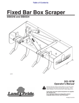
Hydraulic Chute Option Assembly
Refer to Figure 1-5:
1. Assemble Chute (#1) to the main frame with hinge
pin (#2) and cotter pins (#3). Bend one leg of each
cotter pin to keep cotter pin from falling out.
2. Attach hydraulic cylinder tothe chute andframe lugs
as shown with clevis pins (#4). Secure clevis pins
with hair pin cotters.
3. Route hydraulic hoses through hose guide (#5) as
shown.
Hydraulic Chute Option Assembly
Figure 1-5
20522
6. Hook driveline safety chain in the hole in the inner
driveline guard. Attach the other end to the Powered
Ditcher’s main frame.
7. Start tractor and raise Powered Ditcher just enough
to remove support blocks.
8. Slowly engage tractor’s 3-point controls to lower
Powered Ditcher. Check for sufficient drawbar
clearance. Move drawbar ahead, aside or remove if
required.
9. Raise and lower implement to find the maximum
possible extended driveline length. Check to make
certain that the driveline has not extended beyond
the maximum allowable length recorded in step 3 on
page 9.
Manual Chute Option Assembly
Refer to Figure 1-4:
1. Assemble Chute (#1) to the main frame with hinge
pin (#3) and cotter pins (#4). Bend one leg of each
cotter pin to keep cotter pin from falling out.
2. Attach ratchet jack (#5) to the chute and frame lugs
as shown with clevis pins provided. Secure clevis
pins with hair pin cotters.
Manual Chute Option Assembly
Figure 1-4
IMPORTANT: A small chain is supplied with the
driveline. This chain must be attached to the inner
driveline shield and to the Powered Ditcher to
restrict shield rotation.
20529

11
Section 1: Assembly and Set-Up
3/17/08
DT55 & DTM55 Powered Ditchers 324-053M
Land Pride
Table of Contents
Ripper Option Assembly
Refer to Figure 1-6:
1. Assemble ripper Assembly (#1) to the main frame
with four 3/4” u-bolts (#2), lock washers (#3) and
3/4” nuts (#4). Tighten nuts to 170 ft-lbs. of torque.
Ripper Option Assembly
Figure 1-6
Skid Shoe Option Assembly
Refer to Figure 1-7:
1. Attach Skid Shoe (#1) to the main frame with
3/8”-16 x 1 1/4” GR5 round head square neck
bolt s (#2) and lock nuts (#3). Draw lock nuts up
snug, do not tighten.
2. Attach one end of turnbuckle (#5) to the main frame
lug with clevis pin (#6) and cotter pin (#4).
3. Attach other end of turnbuckle (#5) to the lug on the
skid shoe (#1) lug with clevis pin (#6) and cotter
pin (#4).
4. Bend one leg of each cotter pin to keep cotter pin
from falling out.
Gauge Wheel Option Assembly
Refer to Figure 1-8:
1. Assemble Gauge Wheel Assembly (#1) with hitch
pin (#2) and hair pin (#3).
20520
Skid Shoe Option Assembly
Figure 1-7
Gauge Wheel Option Assembly
Figure 1-8
25754
20519

12
Section 2: Operating Instructions
DT55 & DTM55 Powered Ditchers 324-053M
3/17/08
Land Pride
Table of Contents
Section 2: Operating Instructions
Transporting
1. When raising the Powered Ditcher to the transport
position, be sure that the powershaft does not
contact tractor or implement.
2. Be sure to reduce tractor ground speed when
turning. Leave enough clearance so the Powered
Ditcher does not contact obstacles such as
buildings, trees or fences.
3. Select a safe ground travel speed when transporting
from one area to another. When traveling on
roadways, transport in sucha way that fastermoving
vehicles may pass you safely.
4. Whentraveling overroughorhilly terrain,shifttractor
to a lower gear.
!
CAUTION
Whentravelingon public roads,whetherat night or during the
day, use accessory lights and devices for adequate warning to
operatorsof other vehicles. Comply with all federal,state, and
local laws.
Operating Checklist
Operating Instructions
1. Operate with 540 rpm PTO tractor on the DT55 and
1000 rpm PTO on the DTM55.
2. Engage PTO at approximately 200 RPM and slowly
increase to proper PTO RPM.
3. Ditching should not be done in wet conditions assoil
will stick to the blades and reduce the digging ability
of the Ditcher.
4. DO NOT make sharp turns or attempt to back up
while Ditcher is in the ground.
Check Reference
Check chain tension. Refer to “Drive
Chain Adjustment”.
Section 3
page 14
Check oil level in chaincase. Refer to
“Lubrication”.
Section 4
page 18
Check that all plugs have been replaced
properly in the chaincase.
Section 4
page 18
Check that all bolts and nuts are tight. Operator’s
Manual
Be certain allguards andshields arein place
and secure.
Operator’s
Manual
Grease driveline shaft and all other grease
fittings. Refer to “Lubrication”.
Section 4
page 18
Checkairpressure ingaugewheeltire.Refer
to Tire Inflation Chart for tire pressure.
Section 8
page 23
IMPORTANT: ALWAYS disengage PTO before
raising the Powered Ditcher to transport position.
5. DONOTengagePTOwithmachineinthefullyraised
position.
6. DO NOT drop 3 point hitch. Lower the Powered
Ditcher slowly to the ground.
7. Ground speed should be between 3 and 5 mph for
normal conditions. Under extreme rocky conditions
ground speed may have to be reduced for
satisfactory performance. In general, the slower the
ground speed the better job.
8. Proper operating depth and ground speed are
interrelatedand performanceof thePoweredDitcher
will improve with operator experience.
9. Periodically check for foreign objects wrapped
around the blades and remove them after
disengaging PTO, turning off tractor, and removing
ignition key.
General Operating Instructions
Now that you have familiarized yourself with the
Operator’s Manual, completed the Operator’s Checklist
and properly attached your Powered Ditcher to your
tractor, you are almost ready to begin using your Land
Pride 55 Series Powered Ditcher.
It is now time to do a running operational safety check. If
at any time during this safety check if you detect a
malfunction in either the Powered Ditcher or tractor, shut
tractor off immediately, remove switch key, and make
necessary repairs or adjustments before continuing on.
Make sure the tractor’s park brake is engaged, the
tractor’s PTO is disengaged, the Powered Ditcher is
slightly off of the ground and the power shaft is not in a
bind.Startthetractorandthenbackthetractorthrottleoff
until the engine is at low idle. With the tractor running at
an idle speed, make sure if equiped, that the optional
hydraulically controlled material deflector chute is
operating properly for on the go adjustment with the
tractor’s hydraulic controls. This is also the time to make
sure that the rear hydraulic control arms will lower the
Powered Ditcher from transport to working position and
back without putting the power shaft into a bind. Again,
lift the Powered Ditcher slightly off of the ground and
raise the engine rpm slightly. Engage the PTO drive and
check to make sure everything is running smoothly. If
not,safelyshutthetractordownandmakethenecessary
corrections. If everything is in proper working condition,
you are ready to move to the work site.
You should inspect the area where you intend to work
making sure that there are no obvious debris, large
rocks, or other materials that are in your working path.
You will also want to makesure that there areno people,
animals, pets, valuable property and/orequipment in the
immediate vicinity that could be harmed by flying rocks,
dirt, or debris once you engage the Powered Ditcher.

13
Section 2: Operating Instructions
3/17/08
DT55 & DTM55 Powered Ditchers 324-053M
Land Pride
Table of Contents
If your unit has an optional depth controlling skid shoe
and if you have not already set it to the desired depth,
you should set the tractor’s park brake, shut tractor
engine off, remove switch key and then make that
setting.
Youarenowreadytobeginoperation.Makesuretheunit
is lifted just barely off of the ground, raise the tractor
engine rpm slightly aboveidle andengage thePTO. The
best ditching performance is usuallyachieved at forward
speeds of approximately 3 to 5 mph, so make the proper
gear selection and then raise engine rpm to full PTO
speed. Begin forward motion while gently lowering the
Powered Ditcher into working position. You will
immediatelybegin to seeagenerous stream ofdirt being
rapidly ejected off to the left side.
If you arenot using a deflector shield, the dirt willusually
be ejected outward and will spread evenly over the
ground20’ to50’ out.Ifyou areusing adeflector shieldto
forma burmor terrace, nowis thetimeto makesure your
chuteiscorrectlyadjusted toachievethedesiredresults.
After you have traveled approximately 50’, it is a good
idea to lift the Powered Ditcher outof workingposition or
soil contact, safely shut your equipment down, and go
back to inspect the results. Then make required
adjustments before continuing on.
If your ground conditions are extremely hard, you may
find it necessary to employ an optional ripper
attachment. If your ground conditions are too wet, you
shouldn’t run at all until drier conditions prevail.
Remember to look back often. With a little practice you
will gain the required experience you need to help you
achieve the desired results you expect from your
Land Pride 55 Series Powered Ditcher.
Whenyou aredone ditching,need totake abreak, orjust
need to make afew adjustmentsto the Powered Ditcher,
always remember to do the following:
• Raise the Powered Ditcher up and out of soil contact
• Reduce the tractor’s engine rpm
• Disengage the PTO
• Stop on level ground
• Set the park brake
• Turn off the engine
• Remove the key
See “Features and Benefits” section or “Product
Specifications” for additional information and
performance enhancing options.

14
Section 3: Adjustments
DT55 & DTM55 Powered Ditchers 324-053M
3/17/08
Land Pride
Table of Contents
Section 3: Adjustments
!
CAUTION
BEFORE any adjustments are performed, lower the Ditcherto
the ground slowly, stop tractor engine and remove switch key.
DO NOT attempt to make adjustments while tractor is
running.
Drive Chain Adjustment
Refer to Figure 3-1:
1. Unbolt and remove inspection cover (#1). Be careful
not to damage gasket (#7) while removing the cover.
2. Check roller chain for tightness by pressing on the
chain between top and bottom sprockets. Chain
should have approximately 1/2” movement.
3. If the chain is loose, loosen jam nut (#5) and turn
chain adjusting bolt (#3) until excess chain slack is
removed.
4. Tighten jam nut (#5) and recheck chain tension.
5. Replace gasket (#7) if damaged during removal of
inspection cover.
6. Attach inspection cover (#1) to the main frame with
1/4”-20 x5/8”GR5 hexhead cap screw(#4) and lock
washer(#6). Tightencap screw to the correcttorque.
Idler Spring Adjustment
Figure 3-1
NOTE: For corrrect torque values, refer to “Torque
Values Chart For Common Bolt Size” on page 23.
IMPORTANT: Do Notovertightendrivechain. Atight
chain will have high wear.
IMPORTANT: Loctite is required on all bolts (#4) and
silicone is required on gasket (#7) before installation.
25755
Gauge Wheel
Refer to Figure 3-2:
The Gauge Wheel can be adjusted by removing 3/4”
hitchpin(#3)andmovinggaugewheel(#1)upordownto
desired depth. Be sure to secure hitch pin with hair pin
cotter (#4) when reinstalling.
Ripper Depth Adjustment
Refer to Figure 3-2:
The Ripper option is designed to tear up hard ground for
easier ditching.
Adjust ripper to desired depth by removing pins (#6) and
moving the ripper shank (#2) up or down. Replace
retaining pins and secure with hair pin cotters (#5).
Gauge Wheel Adjustment
Figure 3-2
25753

15
Section 3: Adjustments
3/17/08
DT55 & DTM55 Powered Ditchers 324-053M
Land Pride
Table of Contents
Manual Chute Adjustment
Refer to Figure 3-3:
The Chute controls how far and how high debris will be
dispersed.Raise thechute todisperse debris fartherand
higher. Lower the chute to limit how far and how high
debris is dispersed. Raise or lower the chute by setting
theratchet mechanism on the jackand then pumping the
jack handle.
Manual Chute Adjustment
Figure 3-3
20514
Hydraulic Chute Adjustment
!
CAUTION
BEFORE any adjustments are performed, lower the Ditcherto
the ground, stop tractor engine and remove switch key. DO
NOT attempt to make adjustments while tractor is running.
Refer to Figure 3-4:
The Chute can be adjusted hydraulically to the desired
height by adjusting tractor hydraulics.
Hydraulic Chute Adjustment
Figure 3-4
25756

16
Section 4: Maintenance & Lubrication
DT55 & DTM55 Powered Ditchers 324-053M
3/17/08
Land Pride
Table of Contents
Section 4: Maintenance & Lubrication
Storage
For short periods, coat all exposed cylinder shafts with
grease or a corrosion preventive.
Install dust caps on the quick couplers, if equipped, to
prevent dirt contamination of the hydraulic system. Or, if
possible, connect the quick couplers together.
At the end of the workingseason or when theDitcher will
not be used for a long period, it is good practice to clean
off any dirt or grease that may have accumulated on the
Ditcherand anyof the movingparts. It maybe necessary
to scrape off compacted dirt from the rotor blades, then
use a garden hose to thoroughly clean the surface.
Inspectthe Ditcherfor loose,damaged orworn partsand
adjust or replace if needed.
Lubricate as noted in the Lubrication portion of this
section starting on page 18.
Repaintpartswherepaintiswornorscratchedtoprevent
rust. Aerosol touch-up paint is available from your Land
Pridedealer.OrderLandPridepart# 821-002CforBlack
or #821-011C for beige.
Store Ditcher in a clean, dry place.
Drive Chain Maintenance
Theoperator shouldcheck periodically tomake sure that
the drive chain is tight. If adjustment is needed refer to
“Drive Chain Adjustment” on page 14.
Maintenance
Properservicingand adjustmentisthe keytothe longlife
of any implement. With careful and systematic
inspection, you can avoid costly maintenance, time and
repair.
!
CAUTION
For safety reasons, each maintenance operation must be
performed with the Ditcher lowered completely to the ground
or folded with the transport boom lock engaged and the
tractor engine shut off with ignition key removed.
• AfterusingtheDitcherforseveralhours,checkallbolts
to be sure they are tight. For corrrect torque values,
refer to “Torque Values Chart For Common Bolt Size”
on page 23.
• Lubricate items as listed under Lubrication, in this
section, starting on page 18.
• Replace any worn,damaged or illegible safety labels by
obtaining new labelsfrom your Land Pride Dealer.
Information about labelsis located under Safety Labels in
the “Important Safety Information” section starting on
page 1.

17
Section 4: Maintenance & Lubrication
3/17/08
DT55 & DTM55 Powered Ditchers 324-053M
Land Pride
Table of Contents
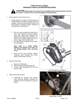
Drive Sprocket and Drive Chain
Replacement
Refer to Figure 4-1:
1. Remove top cover plate (#1) and rear inspection
plate (#2).
2. Loosenjam nut (#14) andidler adjustment bolt (#10).
3. Roll master link (#23) in dual #80 roller chain to top
center and remove.
4. Remove chain by pulling chain from the top.
5. Replace idler sprockets (#22) by removing tightener
assembly (#3) from inside the chain case.
a. Unscrew 3/8” nuts (#15) and remove tightener
assembly (#3).
b. Remove cap screw (#9), spacers (#5 & #6) and
sprockets (#22). Keep cap screw and spacers for
reuse.
c. Install new sprockets (#22) by inserting 3/4”-10 x
3 1/2” GR5 hex head cap screw threw idler
bracket (#3), spacer (#6), sprocket (#22),
sprocket spacer (#5), sprocket (#22), spacer (#6)
and out through idler bracket (#3). Secure with
lock nut (#13).
d. Bolt idler assembly to inside of chain case with
existing 3/8”-16 hex flange lock nuts (#15).
Tighten 3/8” nuts to the correct torque.
6. Replace drive sprocket (#20) and driven sprocket
(#21) as follows:
a. Remove lock collars (#31) from rear flange
bearings (#29) and front flange bearings (#30).
b. Remove 5/8”-11 x 1 1/2” GR5 hex cap
screws (#8), lock washers (#18), rear flange
bearings (#29) and bearing gaskets (#26).
c. Loosen set screws in sprockets (#20 & #21).
There are 2 set screws for each sprocket.
d. Pull upper drive shaft (#25)and lower impeller
shaft(#4) towardsfrontof implement whilesliding
sprockets (#20 & #21) off the shafts. Be careful
not to loose woodruff keys (#7).
e. Installnewsprockets(#20)andreassemble
by reversing above process.
7. Install new chain from the top by using a pull line or
wiretohelp guidechain aroundsprocketsso youcan
add master link at top center. Refer to “Drive Chain
Adjustment” on page 14 to properly adjust roller
chain tension.
8. Install rear inspection plate (#2) and gasket (#27)
with lock washer (#16) and 1/4”-2 x 5/8” GR5 hex
head cap screws (#11).
IMPORTANT: Loctite is required on all installed bolts
and silicone is required on all installed gaskets.
9. Install top cover plate (#1) and cover gasket (#28)
with galvanized rubber clad washers (#19), lock
washers (#17) and 3/8”-16 x 1 1/4” GR5 hex head
cap screws (#12). Tighten cap screws to the correct
torque.
Drive Sprocket and Drive Chain Replacement
Figure 4-1
IMPORTANT: Make sure not to forget to install 3/8”
galvanizedrubber cladwashers (#19). If not replaced
oil could leak out during operation.
20532

18
Section 4: Maintenance & Lubrication
DT55 & DTM55 Powered Ditchers 324-053M
3/17/08
Land Pride
Table of Contents
Output Shaft Bearings
Type of Lubrication: Multi-purpose Grease
Quantity = As required
Input Shaft Bearing
Type of Lubrication: Multi-purpose Grease
Quantity = As required
Lubrication
25758
Drive Chain
Oil should escape from Oil Level plug hole in chain case
when the level plug is removed.
If oil is needed, remove top fill plug and add oil until it
escapes from Oil level plug hole.
Type of Lubrication: Shell Alvania EP00 Gear Lube
Land Pride Part #821-045C (32 oz. bottle)
50
Multi-purpose
spray lube
Multi-purpose
grease lube
Intervals in hours
at which lubrication
is required
Lubrication
Legend
Multi-purpose
oil lube
10
Hours
10
Hours
As
Required
25758
25758
Oil Fill Plug
Oil Level Plug
Drain Plug
/