
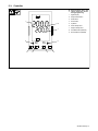
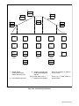
IH/TS
Processes
Description
OM-203 185F
2005−09
Induction Heating
Single Induction Heating Power Source
Temperature Control/Recorder
Visit our website at
www.MillerWelds.com
File: Induction Heating

Miller Electric manufactures a full line
of welders and welding related equipment.
For information on other quality Miller
products, contact your local Miller distributor to receive the latest full
line catalog or individual specification sheets. To locate your nearest
distributor or service agency call 1-800-4-A-Miller, or visit us at
www.MillerWelds.com on the web.
Thank you and congratulations on choosing Miller. Now you can get
the job done and get it done right. We know you don’t have time to do
it any other way.
That’s why when Niels Miller first started building arc welders in 1929,
he made sure his products offered long-lasting value and superior
quality. Like you, his customers couldn’t afford anything less. Miller
products had to be more than the best they could be. They had to be the
best you could buy.
Today, the people that build and sell Miller products continue the
tradition. They’re just as committed to providing equipment and service
that meets the high standards of quality and value established in 1929.
This Owner’s Manual is designed to help you get the most out of your
Miller products. Please take time to read the Safety precautions. They
will help you protect yourself against potential hazards on the worksite.
We’ve made installation and operation quick
and easy. With Miller you can count on years
of reliable service with proper maintenance.
And if for some reason the unit needs repair,
there’s a Troubleshooting section that will
help you figure out what the problem is. The
parts list will then help you to decide the
exact part you may need to fix the problem.
Warranty and service information for your
particular model are also provided.
Miller is the first welding
equipment manufacturer in
the U.S.A. to be registered to
the ISO 9001:2000 Quality
System Standard.
Working as hard as you do
− every power source from
Miller is backed by the most
hassle-free warranty in the
business.
From Miller to You
Mil_Thank 4/05

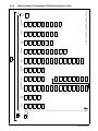
TABLE OF CONTENTS
SECTION 1 − SAFETY PRECAUTIONS − READ BEFORE USING 1 . . . . . . . . . . . . . . . . . . . . . . . . . . . . . . . . . .
1-1. Symbol Usage 1 . . . . . . . . . . . . . . . . . . . . . . . . . . . . . . . . . . . . . . . . . . . . . . . . . . . . . . . . . . . . . . . . . . . . . . . .
1-2. Induction Heating Hazards 1 . . . . . . . . . . . . . . . . . . . . . . . . . . . . . . . . . . . . . . . . . . . . . . . . . . . . . . . . . . . . .
1-3. Additional Symbols for Installation, Operation, and Maintenance 2 . . . . . . . . . . . . . . . . . . . . . . . . . . . . . .
1-4. California Proposition 65 Warnings 2 . . . . . . . . . . . . . . . . . . . . . . . . . . . . . . . . . . . . . . . . . . . . . . . . . . . . . . .
1-5. Principal Safety Standards 2 . . . . . . . . . . . . . . . . . . . . . . . . . . . . . . . . . . . . . . . . . . . . . . . . . . . . . . . . . . . . .
1-6. EMF Information 3 . . . . . . . . . . . . . . . . . . . . . . . . . . . . . . . . . . . . . . . . . . . . . . . . . . . . . . . . . . . . . . . . . . . . . .
SECTION 2 − MESURES DE SECURITE POUR LE CHAUFFAGE PAR INDUCTION 4 . . . . . . . . . . . . . . . . . . .
2-1. Dangers supplémentaires de mise en route, de fonctionnement et d’entretien 5 . . . . . . . . . . . . . . . . . . .
2-2. Informations concernant les champs électro-magnétiques (Information EMF) 6 . . . . . . . . . . . . . . . . . . .
2-3. PRINCIPALES NORMES DE SÉCURITÉ 6 . . . . . . . . . . . . . . . . . . . . . . . . . . . . . . . . . . . . . . . . . . . . . . . . .
SECTION 3 − INTRODUCTION 7 . . . . . . . . . . . . . . . . . . . . . . . . . . . . . . . . . . . . . . . . . . . . . . . . . . . . . . . . . . . . . . . . .
SECTION 4 − INSTALLATION 8 . . . . . . . . . . . . . . . . . . . . . . . . . . . . . . . . . . . . . . . . . . . . . . . . . . . . . . . . . . . . . . . . . .
4-1. Specifications 8 . . . . . . . . . . . . . . . . . . . . . . . . . . . . . . . . . . . . . . . . . . . . . . . . . . . . . . . . . . . . . . . . . . . . . . . .
4-2. IH/TS Installation 8 . . . . . . . . . . . . . . . . . . . . . . . . . . . . . . . . . . . . . . . . . . . . . . . . . . . . . . . . . . . . . . . . . . . . . .
4-3. Connecting To Power Source 9 . . . . . . . . . . . . . . . . . . . . . . . . . . . . . . . . . . . . . . . . . . . . . . . . . . . . . . . . . . .
4-4. Input 14 Pin Information For Receptacle RC1 9 . . . . . . . . . . . . . . . . . . . . . . . . . . . . . . . . . . . . . . . . . . . . . .
4-5. Connecting 25kW System Cords And Cables 10 . . . . . . . . . . . . . . . . . . . . . . . . . . . . . . . . . . . . . . . . . . . . . .
4-6. Connecting 5kW System Cords And Cables 11 . . . . . . . . . . . . . . . . . . . . . . . . . . . . . . . . . . . . . . . . . . . . . . .
4-7. Connecting External Device 12 . . . . . . . . . . . . . . . . . . . . . . . . . . . . . . . . . . . . . . . . . . . . . . . . . . . . . . . . . . . .
SECTION 5 − COMPONENTS AND CONTROLS 13 . . . . . . . . . . . . . . . . . . . . . . . . . . . . . . . . . . . . . . . . . . . . . . . . . .
5-1. IH/TS Front Panel 13 . . . . . . . . . . . . . . . . . . . . . . . . . . . . . . . . . . . . . . . . . . . . . . . . . . . . . . . . . . . . . . . . . . . . .
5-2. IH/TS Rear Panel 14 . . . . . . . . . . . . . . . . . . . . . . . . . . . . . . . . . . . . . . . . . . . . . . . . . . . . . . . . . . . . . . . . . . . . .
5-3. Controller 15 . . . . . . . . . . . . . . . . . . . . . . . . . . . . . . . . . . . . . . . . . . . . . . . . . . . . . . . . . . . . . . . . . . . . . . . . . . . .
SECTION 6 − SETUP AND OPERATION 16 . . . . . . . . . . . . . . . . . . . . . . . . . . . . . . . . . . . . . . . . . . . . . . . . . . . . . . . .
6-1. Safety Equipment 16 . . . . . . . . . . . . . . . . . . . . . . . . . . . . . . . . . . . . . . . . . . . . . . . . . . . . . . . . . . . . . . . . . . . . .
6-2. IH/TS Setup 16 . . . . . . . . . . . . . . . . . . . . . . . . . . . . . . . . . . . . . . . . . . . . . . . . . . . . . . . . . . . . . . . . . . . . . . . . . .
6-2-1. Select Power Source 16 . . . . . . . . . . . . . . . . . . . . . . . . . . . . . . . . . . . . . . . . . . . . . . . . . . . . . . . . . . . . . . .
6-2-2. Time Date Setup − Digital 17 . . . . . . . . . . . . . . . . . . . . . . . . . . . . . . . . . . . . . . . . . . . . . . . . . . . . . . . . . . . .
6-2-2-1. Digital Recorder Controls 17 . . . . . . . . . . . . . . . . . . . . . . . . . . . . . . . . . . . . . . . . . . . . . . . . . . . . . . . . .
6-2-2-2. Login As Engineer 17 . . . . . . . . . . . . . . . . . . . . . . . . . . . . . . . . . . . . . . . . . . . . . . . . . . . . . . . . . . . . . .
6-2-2-3. Go To Operator Screen 17 . . . . . . . . . . . . . . . . . . . . . . . . . . . . . . . . . . . . . . . . . . . . . . . . . . . . . . . . . .
6-2-2-4. Locale Setup 17 . . . . . . . . . . . . . . . . . . . . . . . . . . . . . . . . . . . . . . . . . . . . . . . . . . . . . . . . . . . . . . . . . . .
6-2-2-5. Time And Date Setup 18 . . . . . . . . . . . . . . . . . . . . . . . . . . . . . . . . . . . . . . . . . . . . . . . . . . . . . . . . . . . .
6-2-2-6. Login As User 18 . . . . . . . . . . . . . . . . . . . . . . . . . . . . . . . . . . . . . . . . . . . . . . . . . . . . . . . . . . . . . . . . . .
6-2-2-7. Go To Home Screen 18 . . . . . . . . . . . . . . . . . . . . . . . . . . . . . . . . . . . . . . . . . . . . . . . . . . . . . . . . . . . . .
6-2-2-8. Channel Cycling On/Off And Notes 18 . . . . . . . . . . . . . . . . . . . . . . . . . . . . . . . . . . . . . . . . . . . . . . . .
6-3. Operation 19 . . . . . . . . . . . . . . . . . . . . . . . . . . . . . . . . . . . . . . . . . . . . . . . . . . . . . . . . . . . . . . . . . . . . . . . . . . . .
6-3-1. 2408 Controller 20 . . . . . . . . . . . . . . . . . . . . . . . . . . . . . . . . . . . . . . . . . . . . . . . . . . . . . . . . . . . . . . . . . . . .
6-3-1-1. 2408 Controller Operation 20 . . . . . . . . . . . . . . . . . . . . . . . . . . . . . . . . . . . . . . . . . . . . . . . . . . . . . . . .
6-3-2. Programming The 2408 Controller 21 . . . . . . . . . . . . . . . . . . . . . . . . . . . . . . . . . . . . . . . . . . . . . . . . . . . . .
6-3-3. Batch Recording Using 5100 Digital Recorder 26 . . . . . . . . . . . . . . . . . . . . . . . . . . . . . . . . . . . . . . . . . . .
6-3-3-1. Login As User 26 . . . . . . . . . . . . . . . . . . . . . . . . . . . . . . . . . . . . . . . . . . . . . . . . . . . . . . . . . . . . . . . . . .
6-3-3-2. Start Recording 26 . . . . . . . . . . . . . . . . . . . . . . . . . . . . . . . . . . . . . . . . . . . . . . . . . . . . . . . . . . . . . . . . .
6-3-3-3. Stop Recording 27 . . . . . . . . . . . . . . . . . . . . . . . . . . . . . . . . . . . . . . . . . . . . . . . . . . . . . . . . . . . . . . . . .
6-3-3-4. Saving Data To A Disk (Recommended After Each Batch) 27 . . . . . . . . . . . . . . . . . . . . . . . . . . . . .
6-3-3-5. Saving Data To A PC (Alternative To Floppy Disk) 27 . . . . . . . . . . . . . . . . . . . . . . . . . . . . . . . . . . . .
6-3-3-5-1. Review Software − First Time Setup 27 . . . . . . . . . . . . . . . . . . . . . . . . . . . . . . . . . . . . . . . . . . .
6-3-3-5-2. Creating A Shortcut − First Time Setup 27 . . . . . . . . . . . . . . . . . . . . . . . . . . . . . . . . . . . . . . . . .
6-3-3-5-3. Changing IP Address To Connect The IH/TS 28 . . . . . . . . . . . . . . . . . . . . . . . . . . . . . . . . . . . .
6-3-3-5-4. Downloading Files From Recorder 28 . . . . . . . . . . . . . . . . . . . . . . . . . . . . . . . . . . . . . . . . . . . . .
6-3-3-5-5. Troubleshooting Connection Problems 29 . . . . . . . . . . . . . . . . . . . . . . . . . . . . . . . . . . . . . . . . .
6-3-3-5-6. Resetting IP Address (Necessary To Connect User’s PC To Company’s Network) 29 . . . . .
6-3-4. Running A Program To Preheat Or Stress Relief 30 . . . . . . . . . . . . . . . . . . . . . . . . . . . . . . . . . . . . . . . . .

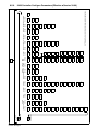
TABLE OF CONTENTS
6-3-5. Recovering From An Interruption 31 . . . . . . . . . . . . . . . . . . . . . . . . . . . . . . . . . . . . . . . . . . . . . . . . . . . . . .
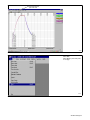
6-3-6. Viewing Data In Review Software 32 . . . . . . . . . . . . . . . . . . . . . . . . . . . . . . . . . . . . . . . . . . . . . . . . . . . . .
6-3-6-1. Installing Review Software And First Time Setup 32 . . . . . . . . . . . . . . . . . . . . . . . . . . . . . . . . . . . . .
6-3-6-2. Backing Up The Database 32 . . . . . . . . . . . . . . . . . . . . . . . . . . . . . . . . . . . . . . . . . . . . . . . . . . . . . . . .
6-3-7. Running Review Software 33 . . . . . . . . . . . . . . . . . . . . . . . . . . . . . . . . . . . . . . . . . . . . . . . . . . . . . . . . . . .
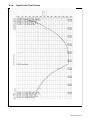
6-3-8. Typical Profile Chart Printout 47 . . . . . . . . . . . . . . . . . . . . . . . . . . . . . . . . . . . . . . . . . . . . . . . . . . . . . . . . .
SECTION 7 − CONFIGURING CONTROLLER AND RECORDER 48 . . . . . . . . . . . . . . . . . . . . . . . . . . . . . . . . . . .
7-1. Changing Controller Operating Window, Ramp, Dwell, Or Temperature Units 48 . . . . . . . . . . . . . . . . . . . .
7-2. Changing 5100V Recorder From Degrees F to Degrees C And Change TC Descriptor 49 . . . . . . . . . . .
7-3. Restoring Recorder Configuration From A Floppy Disk
(For 5100 Digital Recorder) 50 . . . . . . . . . . . . . . . . . . . . . . . . . . . . . . . . . . . . . . . . . . . . . . . . . . . . . . . . . . . . .
7-3-1. Load File 50 . . . . . . . . . . . . . . . . . . . . . . . . . . . . . . . . . . . . . . . . . . . . . . . . . . . . . . . . . . . . . . . . . . . . . . . . . .
7-3-2. Date Setup 50 . . . . . . . . . . . . . . . . . . . . . . . . . . . . . . . . . . . . . . . . . . . . . . . . . . . . . . . . . . . . . . . . . . . . . . . .
7-3-3. Time Setup 51 . . . . . . . . . . . . . . . . . . . . . . . . . . . . . . . . . . . . . . . . . . . . . . . . . . . . . . . . . . . . . . . . . . . . . . . .
7-3-4. Login As User 51 . . . . . . . . . . . . . . . . . . . . . . . . . . . . . . . . . . . . . . . . . . . . . . . . . . . . . . . . . . . . . . . . . . . . .
7-3-5. Go To Home Screen 51 . . . . . . . . . . . . . . . . . . . . . . . . . . . . . . . . . . . . . . . . . . . . . . . . . . . . . . . . . . . . . . . .
SECTION 8 − MAINTENANCE & TROUBLESHOOTING 52 . . . . . . . . . . . . . . . . . . . . . . . . . . . . . . . . . . . . . . . . . . .
8-1. Routine Maintenance 52 . . . . . . . . . . . . . . . . . . . . . . . . . . . . . . . . . . . . . . . . . . . . . . . . . . . . . . . . . . . . . . . . . .
8-2. Troubleshooting 52 . . . . . . . . . . . . . . . . . . . . . . . . . . . . . . . . . . . . . . . . . . . . . . . . . . . . . . . . . . . . . . . . . . . . . .
8-3. Diagnostic Procedures For IH/TS 55 . . . . . . . . . . . . . . . . . . . . . . . . . . . . . . . . . . . . . . . . . . . . . . . . . . . . . . . .
8-4. Resetting All RAM Variables In The Event Of Display Errors 58 . . . . . . . . . . . . . . . . . . . . . . . . . . . . . . . . .
8-5. Factory Set Parameters 59 . . . . . . . . . . . . . . . . . . . . . . . . . . . . . . . . . . . . . . . . . . . . . . . . . . . . . . . . . . . . . . . .
8-5-1. Controller Version Number 59 . . . . . . . . . . . . . . . . . . . . . . . . . . . . . . . . . . . . . . . . . . . . . . . . . . . . . . . . . . .
8-5-2. 2408 Controller Edit Parameters 60 . . . . . . . . . . . . . . . . . . . . . . . . . . . . . . . . . . . . . . . . . . . . . . . . . . . . . .
8-5-3. 2408 Controller Full Parameters (Prior To Version V4.09) 61 . . . . . . . . . . . . . . . . . . . . . . . . . . . . . . . . .
8-5-4. 2408 Controller Configure Parameters (Prior To Version V4.09) 62 . . . . . . . . . . . . . . . . . . . . . . . . . . . .
8-5-5. 2408 Controller Full Parameters (Effective w/Version V4.09) 63 . . . . . . . . . . . . . . . . . . . . . . . . . . . . . . .
8-5-6. 2408 Controller Configure Parameters (Effective w/Version V4.09) 64 . . . . . . . . . . . . . . . . . . . . . . . . . .
8-6. Calibration Certification Procedure 65 . . . . . . . . . . . . . . . . . . . . . . . . . . . . . . . . . . . . . . . . . . . . . . . . . . . . . . .
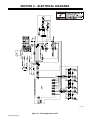
SECTION 9 − ELECTRICAL DIAGRAMS 66 . . . . . . . . . . . . . . . . . . . . . . . . . . . . . . . . . . . . . . . . . . . . . . . . . . . . . . . .
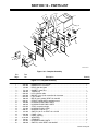
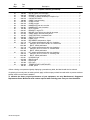
SECTION 10 − PARTS LIST 67 . . . . . . . . . . . . . . . . . . . . . . . . . . . . . . . . . . . . . . . . . . . . . . . . . . . . . . . . . . . . . . . . . . .
WARRANTY

OM-203 185 Page 1
SECTION 1 − SAFETY PRECAUTIONS − READ BEFORE
USING
Y Warning: Protect yourself and others from injury — read and follow these precautions.
1-1. Symbol Usage
safety_ihom 5/05
Means Warning! Watch Out! There are possible hazards
with this procedure! The possible hazards are shown in
the adjoining symbols.
Y Marks a special safety message.
. Means “Note”; not safety related.
This group of symbols means Warning! Watch Out! possible
ELECTRIC SHOCK, MOVING PARTS, and HOT PARTS hazards.
Consult symbols and related instructions below for necessary actions
to avoid the hazards.
1-2. Induction Heating Hazards
Y The symbols shown below are used throughout this manual to
call attention to and identify possible hazards. When you see
the symbol, watch out, and follow the related instructions to
avoid the hazard. The safety information given below is only a
summary of the more complete safety information found in the
Safety Standards listed in Section 1-5. Read and follow all Safe-
ty Standards.
Y Only qualified persons should install, operate, maintain, and
repair this unit.
Y During operation, keep everybody, especially children, away.
ELECTRIC SHOCK can kill.
Touching live electrical parts can cause fatal shocks
or severe burns. The power circuit and output bus
bars or connections are electrically live whenever
the output is on. The input power circuit and machine
internal circuits are also live when power is on. Incorrectly installed or
improperly grounded equipment is a hazard.
D Do not touch live electrical parts.
D Enclose any connecting bus bars and coolant fittings to prevent
unintentional contact.
D Wear dry, hole-free insulating gloves and body protection.
D Insulate yourself from work and ground using dry insulating mats or
covers big enough to prevent any physical contact with the work or
ground.
D Additional safety precautions are required when any of the follow-
ing electrically hazardous conditions are present: in damp locations
or while wearing wet clothing; on metal structures such as floors,
gratings, or scaffolds; when in cramped positions such as sitting,
kneeling, or lying; or when there is a high risk of unavoidable or ac-
cidental contact with the workpiece or ground. For these
conditions, see ANSI Z49.1 listed in Safety Standards. And, do not
work alone!
D Disconnect input power before installing or servicing this equip-
ment. Lockout/tagout input power according to OSHA 29 CFR
1910.147 (see Safety Standards).
D Use only nonconductive coolant hoses with a minimum length of 18
inches (457 mm) to provide isolation.
D Properly install and ground this equipment according to its Owner’s
Manual and national, state, and local codes.
D Always verify the supply ground − check and be sure that input pow-
er cord ground wire is properly connected to ground terminal in
disconnect box or that cord plug is connected to a properly grounded
receptacle outlet.
D When making input connections, attach proper grounding
conductor first − double-check connections.
D Frequently inspect input power cord for damage or bare wiring − re-
place cord immediately if damaged − bare wiring can kill.
D Turn off all equipment when not in use.
D Do not use worn, damaged, undersized, or poorly spliced cables.
D Do not drape cables over your body.
D Do not touch power circuit if you are in contact with the work, ground,
or another power circuit from a different machine.
D Use only well-maintained equipment. Repair or replace damaged
parts at once. Maintain unit according to manual.
D Wear a safety harness if working above floor level.
D Keep all panels and covers securely in place.
SIGNIFICANT DC VOLTAGE exists in inverter-type
power sources after removal of input power.
D Turn Off inverter, disconnect input power, and discharge input
capacitors according to instructions in Maintenance Section before
touching any internal parts.
Induction Heating of certain materials, adhesives,
and fluxes can produce fumes and gases. Breathing
these fumes and gases can be hazardous to your
health.
FUMES AND GASES can be hazardous.
D Keep your head out of the fumes. Do not breathe the fumes.
D If inside, ventilate the area and/or use local forced ventilation to re-
move fumes and gases.
D If ventilation is poor, wear an approved air-supplied respirator.
D Read and understand the Material Safety Data Sheets (MSDSs)
and the manufacturer’s instruction for adhesives, fluxes, metals,
consumables, coatings, cleaners, and degreasers.
D Work in a confined space only if it is well ventilated, or while wearing
an air-supplied respirator. Always have a trained watchperson near-
by. Fumes and gases from heating can displace air and lower the
oxygen level causing injury or death. Be sure the breathing air is
safe.
D Do not heat in locations near degreasing, cleaning, or spraying oper-
ations. The heat can react with vapors to form highly toxic and
irritating gases.
D Do not overheat coated metals, such as galvanized, lead, or
cadmium plated steel, unless the coating is removed from the
heated area, the area is well ventilated, and while wearing an air-
supplied respirator. The coatings and any metals containing these
elements can give off toxic fumes if overheated. See coating MSDS
for temperature information.

OM-203 185 Page 2
FIRE OR EXPLOSION hazard.
D Do not overheat parts and adhesive.
D Watch for fire; keep extinguisher nearby.
D Keep flammables away from work area.
D Do not locate unit on, over, or near combustible surfaces.
D Do not install unit near flammables.
D Do not operate unit in explosive atmosphere.
INDUCTION HEATING can cause burns.
D Hot parts and equipment can injure.
D Do not touch or handle induction head/coil
during operation.
D Do not touch hot parts bare-handed.
D Allow cooling period before handling parts or equipment.
D Keep metal jewelry and other metal personal items away from
head/coil during operation.
1-3. Additional Symbols for Installation, Operation, and Maintenance
FALLING UNIT can cause injury.
D Use handle and have person of adequate
physical strength lift unit.
D Move unit with hand cart or similar device.
D For units without a handle, use equipment of
adequate capacity to lift unit.
D When using lift forks to move unit, be sure forks are long enough
to extend beyond opposite side of unit.
FLYING METAL OR ADHESIVE can injure eyes.
D Wear approved safety glasses with side
shields or wear face shield.
MOVING PARTS can cause injury.
D Keep away from moving parts such as fans.
D Keep all doors, panels, covers, and guards
closed and securely in place.
MAGNETIC FIELDS can affect pacemakers.
D Pacemaker wearers keep away.
D Wearers should consult their doctor before
going near induction heating operations.
OVERUSE can cause OVERHEATING
D Allow cooling period.
D Reduce output or reduce duty cycle before
starting to heat again.
D Follow rated duty cycle.
STATIC (ESD) can damage PC boards.
D Put on grounded wrist strap BEFORE handling
boards or parts.
D Use proper static-proof bags and boxes to
store, move, or ship PC boards.
H.F. RADIATION can cause interference.
D High-frequency (H.F.) can interfere with radio
navigation, safety services, computers, and
communications equipment.
D Have only qualified person familiar with electronic equipment per-
form this installation.
D The user is responsible for having a qualified electrician promptly
correct any interference problem resulting from the installation.
D If notified by the FCC about interference, stop using the equip-
ment at once.
D Have the installation regularly checked and maintained.
D Keep high-frequency source doors and panels tightly shut.
READ INSTRUCTIONS.
D Read Owner’s Manual before using or servic-
ing unit.
D Use only genuine Miller/Hobart replacement
parts.
1-4. California Proposition 65 Warnings
Y Welding or cutting equipment produces fumes or gases which
contain chemicals known to the State of California to cause
birth defects and, in some cases, cancer. (California Health &
Safety Code Section 25249.5 et seq.)
Y Battery posts, terminals and related accessories contain lead
and lead compounds, chemicals known to the State of
California to cause cancer and birth defects or other
reproductive harm. Wash hands after handling.
For Gasoline Engines:
Y Engine exhaust contains chemicals known to the State of
California to cause cancer, birth defects, or other reproductive
harm.
For Diesel Engines:
Y Diesel engine exhaust and some of its constituents are known
to the State of California to cause cancer, birth defects, and oth-
er reproductive harm.
1-5. Principal Safety Standards
Safety in Welding, Cutting, and Allied Processes, ANSI Standard Z49.1,
from Global Engineering Documents (phone: 1-877-413-5184, website:
www.global.ihs.com).
Safety and Health Standards, OSHA 29 CFR 1910, from Superintendent
of Documents, U.S. Government Printing Office, Washington, D.C.
20402.
National Electrical Code, NFPA Standard 70, from National Fire Protec-
tion Association, Batterymarch Park, Quincy, MA 02269.
Canadian Electrical Code Part 1, CSA Standard C22.1, from Canadian
Standards Association, Standards Sales, 178 Rexdale Boulevard,Rex-
dale, Ontario, Canada M9W 1R3.
Practice For Occupational And Educational Eye And Face Protection,
ANSI Standard Z87.1, from American National Standards Institute, 11
West 42nd Street, New York, NY 10036−8002 (phone: 212−642−4900,
website: www.ansi.org).

OM-203 185 Page 3
1-6. EMF Information
Considerations About Induction Heating And The Effects Of Low Fre-
quency Electric And Magnetic Fields
The following is a quotation from the General Conclusions Section of the
U.S. Congress, Office of Technology Assessment, Biological Effects of
Power Frequency Electric & Magnetic Fields − Background Paper, OTA-
BP-E-53 (Washington, DC: U.S. Government Printing Office, May
1989): “. . . there is now a very large volume of scientific findings based
on experiments at the cellular level and from studies with animals and
people which clearly establish that low frequency magnetic fields can in-
teract with, and produce changes in, biological systems. While most of
this work is of very high quality, the results are complex. Current scientif-
ic understanding does not yet allow us to interpret the evidence in a
single coherent framework. Even more frustrating, it does not yet allow
us to draw definite conclusions about questions of possible risk or to of-
fer clear science-based advice on strategies to minimize or avoid
potential risks.”
To reduce magnetic fields in the workplace, use the following proce-
dures:
1. Arrange output cable to one side and away from the operator.
2. Do not coil or drape output cable around the body.
3. Keep power source and cable as far away from the operator as
practical.
About Pacemakers:
Pacemaker wearers consult your doctor before welding or going near
welding or induction heating operations. If cleared by your doctor, then
following the above procedures is recommended.
Page is loading ...
Page is loading ...
Page is loading ...

OM-203 185 Page 7
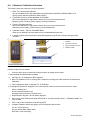
SECTION 3 − INTRODUCTION
The Induction Heating Temperature Station (IH/TS) is designed to be used with Induction Heating Systems for
pre-heat and post-heat (stress relieving) applications. The station is built in two different configurations; as a controller
only or as a controller with a digital recorder.
The controller in the IH/TS comes pre-programmed from the factory with a typical stress relieving temperature profile
that can be easily changed to match specific customer stress relief requirements. Also, the controller can be
programmed to operate in a pre-heat mode. These instructions will guide the operator in the proper use of the station
which includes programming and setting up the controller, and operating the recorder.

OM-203 185 Page 8
SECTION 4 − INSTALLATION
4-1. Specifications
Specification Description
Overall Dimensions Height: 10 in (254 mm); Width: 14-1/2 in (368 mm); Depth: 16 in (406 mm)
Weight Net: IH/TS (no recorder) 13.1 lb (5.9 kg); IH/TS (digital recorder) 21.1 lb (9.6 kg)
Type Of Input Power 24 Volts DC, 115 Volts AC
Memory Capacity One Program Up To 8 Segments
Control Capacity Single Power Source Control
Operating Temperature Range 41° To 104° F (5° To 40° C)
Storage Temperature Range −4° To 122° F (−20° To 50° C)
Reference the controller and recorder manuals for additional information.
Ref. 802 905-A / 802 900
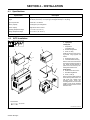
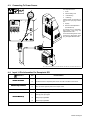
4-2. IH/TS Installation
1
1
Tools Needed:
3/8, 5/16 in
Y Turn Off and disconnect
input power.
5 kW System
1. Temperature
Control/Recorder
2. 5kW Mounting Bracket
3. Screw, 10-32 (4)
Install and secure IH/TS to mount-
ing bracket using supplied #10
screws.
4. 5kW Power Source Case
5. Case Sheet Metal Screw (4)
Remove case sheet metal screws
from both top left and right sides of
unit. Install mounting bracket to
power source and secure by rein-
stalling sheet metal screws.
25 kW System
6. 25 kW Power Source Case
7. Rear Mounting Bracket
8. Screw, 1/4-20 (2)
Remove front and middle mounting
screws from top of Item 6 case. Lo-
cate IH/TS and reinstall front
mounting screws. Locate rear
mounting bracket, and secure with
supplied 1/4-20 screws. Reinstall
middle mounting screws to secure
bracket to case.
3
4
6
2
8
8
7
5
4

OM-203 185 Page 9
4-3. Connecting To Power Source
Turn Off power source.
1. IH/TS
2. Interconnecting Cord
3. 14-Socket Plug
4. 14-Pin Plug
Obtain cord with 14-socket plug on
one end and 14-pin plug on other
end.
5. Keyway
6. Remote 14 Receptacle RC1
(See Section 4-4)
To connect cord to a receptacle,
align keyway, insert plug, and
tighten threaded collar.
To connect remaining end of cord to
power source, align keyway, insert
plug, and tighten threaded collar.
2
sb7.1* 3/93 - Ref. S-0004-A / S-0750 / Ref. 802 926 / Ref. 801 049 / 801 825-B / Ref. 803 004-A
3
4
1
6
JA
I
K
B
H
N
L
C
G
M
D
F
E
5
4-4. Input 14 Pin Information For Receptacle RC1
REMOTE 14
Pin Pin Information
Remote Contactor
A +24 volts dc from power source.
R
emote
C
ontactor
B Contact closure to A completes power source +24 volts dc contactor control circuit.
Remote Output Control
D Control circuit common.
R
emote
O
utput
C
ontro
l
E 0 to +10 volts dc signal for power source output control.
Power Source Fault
F, J Absence of contact closure from power source indicates power source output failure.
I Actual frequency input signal.
Remote Metering*
L Average power input signal.
R
emote
M
eter
i
ng
*
M Voltage input signal RMS.
N Current input signal RMS.
*See power source Owner’s Manual for scaling information.

OM-203 185 Page 10
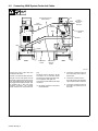
4-5. Connecting 25kW System Cords And Cables
Connect the power output cable and
coolant lines as shown.
Connect 110-volt power cable as shown.
Plug the 110-volt cooler power cord into
the duplex at the rear of the power source
cart. On the 25kW system, the cooler must
be plugged into the right side duplex. This
is identified with a label that reads
“switched receptacle.” The ON-OFF
switch located to the left operates this
plug.
The IH/TS Control is plugged in the left
side duplex. Do not use these duplex
connections for operating auxiliary tools,
such as grinders, drills, lights, etc.
Connect output power cables to the output
connectors.
. All coolant connections have 5/8-18
left-hand threads.
D Connect the “coolant out” line from
the cooler directly to the output ex-
tension cable.
D Connect the “coolant in” line on
the IH/TS directly to the remaining
output extension cable connection.
D Connect the “coolant out” line from
the IH/TS to the “coolant in” line on
the cooler.
803 036-C
Hose From
IH/TS To
Cooler
Blue
14-Pin
Control Cable
Hose
From Power
Source
To IH/TS
110 Volt From
IH/TS
110 Volt From
Cooler
Hose From Cooler To
Power Source
Output
Connectors
Yellow
Blue
Red
Yellow
Red
Front Rear

OM-203 185 Page 11
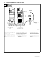
4-6. Connecting 5kW System Cords And Cables
Connect the power output cable and
coolant lines as shown.
Connect 110-volt power cable as shown.
Plug the 110-volt cooler power cord into
the duplex at the rear of the power source
cart.
The IH/TS Control is plugged in the left
side duplex. Do not use these duplex
connections for operating auxiliary tools,
such as grinders, drills, lights, etc.
D Connect the “coolant out” line from
the cooler directly to the output ex-
tension cable.
D Connect the “coolant in” line on
the IH/TS directly to the remaining
output extension cable connection.
D Connect the “coolant out” line from
the IH/TS to the “coolant in” line on
the cooler.
803 040-A
Hose From Cooler To
Output Extension Cable
Hose From IH/TS To
Cooler
Hose From
Output Extension Cable
To IH/TS
Output
Connectors
Front Rear

OM-203 185 Page 12
4-7. Connecting External Device
The IH/TS must have (as a
minimum) one thermocouple
connected to receptacle TC1. If
multiple thermocouples are
desired, either use individual
thermocouple plugs or the
thermocouple extension cable.
To connect thermocouples to the
control, proceed as follows:
Turn Off power source.
1. Temperature Controller
2. Thermocouple Receptacles
3. Individual Thermocouple Plug
4. Thermocouple Extension
Cable
Align plug pins with receptacle
sockets and push plug into
receptacle.
5. Coolant Line From Coil
6. Coolant Line To Cooler
“Coolant In” Port
The IH/TS is supplied with an
internal coolant flow switch.
Coolant hoses must be connected
to the IH/TS for proper operation.
Connect coolant hoses (supplied
with post-heat systems) to coolant
fittings on unit as described in
Section 4-5.
Ref. 803 003-B
Tools Needed:
11/16 in
1
2
3
4
5
6

OM-203 185 Page 13
SECTION 5 − COMPONENTS AND CONTROLS
5-1. IH/TS Front Panel
Y Keep all panels, doors, and
covers closed and secure
during programming.
1. Temperature Controller
2. Parameter Display Screen
3. Heat On Pilot Light
4. Fault/ Limit Light
5. Run Button
6. Hold Button
7. Stop Button
8. Recorder (If Equipped)
1
2
3
4
5
6
7
8
Ref. 803 004

OM-203 185 Page 14
5-2. IH/TS Rear Panel
Y Keep all panels, doors, and
covers closed and secure
during programming.
1. Thermocouple Connectors
2. On/Off Power Switch
3. 115 VAC Power Cord
4. 14-Pin Receptacle
5. Coolant Flow Switch “IN”
Fitting
6. Coolant Flow Switch “OUT”
Fitting
7. Power Source Select Switch
8. Network Connection
Ref. 803 004-A
2
3
4 5 6
8
7
1

OM-203 185 Page 15
5-3. Controller
Y Keep all panels, doors, and
covers closed and secure
during programming.
1. Digital Display
2. Page Forward Button
3. Scroll Button
4. Down Button
5. Up Button
6. Actual Temperature
7. Setpoint Temperature
8. Auto/Man Button (Disabled)
9. Run/Hold Button (Disabled)
1
2
AUTO
MAN
RUN
HOLD
B Y
345
200.0
200.0
OP1
SP2
6
7
9
8

OM-203 185 Page 16
SECTION 6 − SETUP AND OPERATION
6-1. Safety Equipment
Wear the following during
operation:
1. Dry, Insulating Gloves
2. Safety Glasses With Side
Shields
DO NOT wear rings or watches
during operation.
sb3.1* 1/94
12
6-2. IH/TS Setup
6-2-1. Select Power Source
Energize the power source, cooler, and IH/TS. A power source selection will appear in the top right corner of the
IH/TS front panel Parameter Display. Press the recessed Power Source Select button on the IH/TS rear panel to
toggle through and select the appropriate power source maximum output. This selection will provide the proper out-
put scaling in the parameter display screen for the power source that is attached to the IH/TS.
0 . 0 K W P w r PS 2 5
0Amps (rms)
0Volts (rms)
12 .5 KHs Frequency
Parameter Display
Power Source Max Output

OM-203 185 Page 17
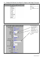
6-2-2. Time Date Setup − Digital
6-2-2-1. Digital Recorder Controls
Y Keep all panels, doors, and
covers closed and secure
during programming.
1. Page Up
2. Page Down
3. Left
4. Right
5. Option
6. Menu
Additional keys that appear as
needed for specific applications are
as follows:
7. Close Folder
8. Open Folder
9. Left Cursor
10. Right Cursor
2
3
4
5
6
7
1
8
9
10
6-2-2-2. Login As Engineer
1. Touch top left corner (Logged Out) or (User).
2. Touch Blue text (pull down menu) next to User.
3. Touch Engineer.
4. Touch Password field.
5. Touch Numeric.
6. Touch 1, then 0, and finally Ok. “Engineer” will appear in top left corner of display.
6-2-2-3. Go To Operator Screen
1. Touch the Menu key in bottom right corner to open Root Menu.
2. Touch Operator.
6-2-2-4. Locale Setup
1. Touch System.
2. Touch Locale.
3. Touch pull down next to Country.
4. Touch appropriate country.
5. Touch pull down next to Time Zone.
6. Touch appropriate time zone (i.e. CST Central). See “http://www.timeanddate.com” for additional information.
7. Set DST (Daylight Savings Time) if applicable. Place an “X” in the box next to “Use Summertime (DST)” to
enable this option.

OM-203 185 Page 18
In general, for those locations that observe DST:
DST begins at 2:00 am on the first Sunday in April.
DST ends at 2:00 am on the last Sunday in October.
See “http://deil.lang.uiuc.edu/web.pages/holidays/DST.html for exceptions.
NOTE
8. Touch Apply.
6-2-2-5. Time And Date Setup
1. Touch System.
2. Touch Clock.
3. Adjust time and date, if necessary.
4. Touch Apply.
6-2-2-6. Login As User
1. Touch top left corner (Engineer).
2. Touch pull down next to User.
3. Touch User from pull down list.
6-2-2-7. Go To Home Screen
1. Touch the Menu key in bottom right corner to open Root Menu.
2. Touch Home.
6-2-2-8. Channel Cycling On/Off And Notes
When Trend graphs are displayed, the operator has the option to sequentially display the TC readings for each
channel by activating the “Channel Cycling On”option. When channel cycling is off, recorder displays only the
selected TC value.
To activate/deactivate “Channel Cycling”:
1. Press the Option key to open options menu.
2. Press channel cycling On to activate cycling or press channel cycling Off to deactivate cycling.
scrn34
To manually change which TC is
displayed, press the TC field to
advance to the next TC reading.
Notes can be added to a chart on
the recorder while viewing a trend
screen.
Press the “Option Menu” button.
Press “Note”.
Press the field next to “User Note”
and enter notes using keypad.
Press “OK”.
Press “OK”.
The note is added to the chart.
The note can be viewed on the
bottom of the screen or in the
history screen.
Press the Option key, press “Enter
History”.
To exit, press the Option key, then
press “Exit History”.

OM-203 185 Page 19
6-3. Operation
1. Energize IH/TS and power source. A coolant flow error should appear on the IH/TS display. Energize the
cooler and the error will clear from the display.
2. Set up Temperature Profile − per code requirements (see Section 6-3-2 Programming The 2408 Controller).
3. Set up and start Digital Recorder
Digital Recorder (see Section 6-3-3. Batch Recording On The 5100 Digital Recorder)
4. Run the heat process (see Section 6-3-4. Running A Heat Treat and the following tables).
5. Recover from an interruption, if applicable (see Section 6-3-5. Recovering From An Interruption).
6. Retrieve data
Digital Recorder (see Section 6-3-3-4. Batch Recording On The 5100 Digital Recorder)
View and print data (see Section 6-3-6 Review Software).
Table 6-1. Controller Display Definitions
Name Description
Home List (extra parameters may be present.)
Home Measured value and Setpoint
OP
% Output level
Table 6-2. Run List Sub-Menu Definitions
run program run List
StAt Program status (OFF, run, hoLd, HbAc, End)
PSP
Programmer setpoint
SEG
Active segment number
StyP
Active segment type
SEG.t
Segment time remaining in the segment units
tGt
Target setpoint
rAtE
Ramp rate (if a rate segment)
PrG.t
Program time remaining in hours
SEG.d
*Flash active segment type in the lower readout of the home display (no/YES)
FASt
Runs through program 10 times faster than normal
*This parameter can only be changed when the program is in reset.
Page is loading ...
Page is loading ...
Page is loading ...
Page is loading ...
Page is loading ...
Page is loading ...
Page is loading ...
Page is loading ...
Page is loading ...
Page is loading ...
Page is loading ...
Page is loading ...
Page is loading ...
Page is loading ...
Page is loading ...
Page is loading ...
Page is loading ...
Page is loading ...
Page is loading ...
Page is loading ...
Page is loading ...
Page is loading ...
Page is loading ...
Page is loading ...
Page is loading ...
Page is loading ...
Page is loading ...
Page is loading ...
Page is loading ...
Page is loading ...
Page is loading ...
Page is loading ...
Page is loading ...
Page is loading ...
Page is loading ...
Page is loading ...
Page is loading ...
Page is loading ...
Page is loading ...
Page is loading ...
Page is loading ...
Page is loading ...
Page is loading ...
Page is loading ...
Page is loading ...
Page is loading ...
Page is loading ...
Page is loading ...
Page is loading ...
Page is loading ...
Page is loading ...
Page is loading ...
Page is loading ...
-
 1
1
-
 2
2
-
 3
3
-
 4
4
-
 5
5
-
 6
6
-
 7
7
-
 8
8
-
 9
9
-
 10
10
-
 11
11
-
 12
12
-
 13
13
-
 14
14
-
 15
15
-
 16
16
-
 17
17
-
 18
18
-
 19
19
-
 20
20
-
 21
21
-
 22
22
-
 23
23
-
 24
24
-
 25
25
-
 26
26
-
 27
27
-
 28
28
-
 29
29
-
 30
30
-
 31
31
-
 32
32
-
 33
33
-
 34
34
-
 35
35
-
 36
36
-
 37
37
-
 38
38
-
 39
39
-
 40
40
-
 41
41
-
 42
42
-
 43
43
-
 44
44
-
 45
45
-
 46
46
-
 47
47
-
 48
48
-
 49
49
-
 50
50
-
 51
51
-
 52
52
-
 53
53
-
 54
54
-
 55
55
-
 56
56
-
 57
57
-
 58
58
-
 59
59
-
 60
60
-
 61
61
-
 62
62
-
 63
63
-
 64
64
-
 65
65
-
 66
66
-
 67
67
-
 68
68
-
 69
69
-
 70
70
-
 71
71
-
 72
72
-
 73
73
-
 74
74
-
 75
75
-
 76
76


Ask a question and I''ll find the answer in the document
Finding information in a document is now easier with AI
Related papers
-
Miller LC257131 Owner's manual
-
-
Miller IH Owner's manual
-
-
-
-
Miller MF080055G Owner's manual
-
Miller PIPEWORX 350 FIELDPRO AND FIELDPRO REMOTE CE Owner's manual
-
Miller SUBARC SYSTEM DIGITAL ACCESSORIES CE Owner's manual
-
Miller MH294053U Owner's manual
Other documents
-
Chromalox 4080 Quick start guide
-
 Carbolite Gero HRF 7/324 with 301 Controller Operating instructions
-
Carbolite Gero CWF 11/23 with 301 Controller Operating instructions
-
 Carbolite Gero HTCR 5/220 with 2416 Controller Operating instructions
-
 Carbolite Gero GP 330A & GP 330B with 2416 Controller Operating instructions
-
 Carbolite Gero HT 4/28 with 2416 Controller Operating instructions
-
 Carbolite Gero CR 30 with 2416 Controller Operating instructions
-
 Carbolite Gero RHF 15/8 with 2416 Controller Operating instructions
-
Eurotherm 2132 / 2116 User guide
-
Eurotherm 2116/2132 Owner's manual


