Page is loading ...

IRW-2PA
O W N E R S M A N U A L
INFRARED WIRELESS
MICROPHONE PA SYSTEM
NADY SYSTEMS, INC.
6701 Shellmound Street • Emeryville, CA 94608 USA
Tel: 510/652-2411 • Fax: 510/652-5075
www.nady.com
IMPORTANT SAFETY INSTRUCTIONS WARNING
An equilateral triangle enclosing a lightning flash/arrowhead symbol
is intended to alert the user to the presence of uninsulated
“dangerous voltage” within the product’s enclosure which may be of
sufficient magnitude to constitute a risk of electric shock.
An equilateral triangle enclosing an exclamation point is intended to
alert the user to the presence of important operating and service
instructions in the literature enclosed with this unit.
ATTENTION: RISQUE DE CHOC ELECTRIQUE NE PAS OUVRIR
When using this electronic device, basic precautions should always be taken, including the
following:
1. Read all instructions before using the product.
2. Do not use this product near water (e.g., near a bathtub, washbowl, kitchen sink, in a wet
basement, or near a swimming pool, etc.).
3. This product should be used only with a cart or stand that will keep it level and stable and
prevent wobbling.
4. This product, in combination with headphones or speakers, may be capable of producing
sound levels that could cause permanent hearing loss. Do not operate for a long period
of time at a high volume level or at a level that is uncomfortable. If you experience any
hearing loss or ringing in the ears, you should consult an audiologist.
5. The product should be positioned so that proper ventilation is maintained.
6. The product should be located away from heat sources such as radiators, heat vents, or
other devices (including ampliers) that produce heat.
7. The product should be connected to a power supply only of the type described in the
operating instructions or as marked on the product. Replace the fuse only with one of the
specied type, size, and correct rating.
8. The power supply cord should: (1) be undamaged, (2) never share an outlet or extension
cord with other devices so that the outlet’s or extension cord’s power rating is exceeded,
and (3) never be left plugged into the outlet when not being used for a long period of
time.
9. Care should be taken so that objects do not fall into, and liquids are not spilled through,
the enclosure’s openings.
10. The product should be serviced by qualied service personnel if:
A. The power supply cord or the plug has been damaged.
B. Objects have fallen into, or liquid has been spilled onto the product.
C. The product has been exposed to rain.
D. The product does not appear to operate normally or exhibits a marked change in
performance.
E. The product has been dropped, or the enclosure damaged.
11. Do not attempt to service the product beyond what is described in the user maintenance
instructions. All other servicing should be referred to qualied service personnel.
This unit is to be installed by qualied personnel only.

CONTENTS .......................................................................................................2
INTRODUCTION ...............................................................................................3
USING THIS MANUAL .......................................................................................3
SYSTEM CONTENTS ..........................................................................................3
SYSTEM FEATURES ............................................................................................4
INSTALLATIONS ................................................................................................5
IRW-2PA RECEIVER ............................................................................................8
IRW-1S INFRARED SENSORS ...........................................................................10
HT-6SC HANDHELD MICROPHONE TRANSMITTER ........................................... 11
LT-6SC BODYPACK TRANSMITTER ....................................................................12
OPTIONAL ACCESSORIES ...............................................................................14
SERVICE ..........................................................................................................14
SPECIFICATIONS .............................................................................................15
SAFTEY WARNING.........................................................................BACK COVER
CONTENTS
2
15
SPECIFICATIONS
IRW-2PA Wireless PA
Mode ..................................................................... Infrared Frequency Modulated
Receiving channels ................................................................. Dual channels A & B
Carrier frequency .................................................... (Ch A) 2.0MH; (Ch B) 2.6MH
Range (line of sight) ..................................................................Up to 50 ft. (15M)
Audio frequency response: ...............................................................60Hz~14KHz
S/N ratio ...................................................................................................>82db
THD .............................................................................................................0.8%
Aux Input sensitivity .....................................................................................18mV
Mic Input sensitivity ....................................................................................280mV
Bass control .............................................................................+/- 12dB at 100Hz
Treble control .............................................................................+/- 12dB at 8Khz
Speaker Output Power ...................................... 35W RMS @ 4Ω; 25W RMS @ 8Ω
Controls .............................Power On/Off (inside panel); A and B Volume controls;
Mic Input Volume; Aux Input Volume; Bass EQ; Treble EQ;
Charging Selector Switch, Battery Charging Power Switch
Connectors ............ 4 x IR Sensor Input coax jacks; Speaker Output dual spring clip;
Aux Input 1⁄4” jack; Mic Input 1⁄4” jack; AC Power Input Jack
Power Requirements ............. AC/AC Power Supply 24VAC 2500mA (UL Approved)
Power Fuse .............................................................................................2A 250V
Dimension (H x W x D) ........................14.1” x 10.6” x 6.2” (358 x 269 x 157mm)
Weight ......................................................................................... 13.2 lbs. (6 kg)
HT-6SC Handheld Microphone Transmitter
Carrier frequency ......................................................Ch A 2.0MHz, Ch B 2.6MHz
Controls ....................................................................................... ON/OFF switch
Audio Input ...........................................DM-10D Unidirectional Dynamic Cartridge
Power Requirement ........................................................... 2xAA battery (2.4VDC)
Battery Life ...................................................................................... Up to 6 hours
Dimensions ................................................................. 2.2” x 10.2” (56 x 260mm)
Weight ..........................................................................................14.1 oz (400g)
LT-6SC Bodypack Transmitter
Carrier frequency ......................................................Ch A 2.0MHz, Ch B 2.6MHz
Audio input ........... LM-14/O lavalier/lapel omni-directional condenser microphone,
DM-14/O direct plug-in omni-directional
condenser microphone, HM-10 condenser headmic
Controls ............................. ON/OFF switch, Volume Control, Ch A/B Select Switch
Connectors .............................................................................3.5 mm locking jack
Power Requirement ........................................................... 2xAA battery (2.4VDC)
NiMH Battery Life ............................................................................ Up to 6 hours
Dimensions ................................................. 3.9” x 1.2” x 2.6” (100 x 30 x 66mm)
Weight ............................................................................................3.6 oz (100g)

14
3
INTRODUCTION
Thank you for purchasing the NADY IRW-2PA Infrared Wireless PA System and con-
gratulations on your choice. The IRW-2PA is loaded with top professional operating
features and is the best performance and price value available in Infrared Wireless
PA Systems.
This booklet gives instructions for the installation and operation of the IRW-2PA sys-
tem, including handheld and lavalier wireless microphone transmitters. Please read
the instructions for your system completely before operating unit.
This manual will rst list the features of the IRW-2PA and then will take you step by
step to show you how to install and operate your new system. After reading the
PA receiver instructions, turn to the section of the booklet that covers the type of
transmitter used with your new system. Each section will give you detailed operat-
ing instructions. Also included in this manual are system specications and servicing
information.
USING THIS MANUAL
• IRW-2PA dual channel wireless infrared receiver
• (2x) Infrared transmitters - either HT-6SC handheld microphone or LT-6SC body-
pack with clip-on lavalier microphone and lanyard
• (2x) IRW-1S Infrared Sensor w/20 ft. and 35 ft. extension cables
• AC/AC Power supply for PA
• (2x) lockbox keys
• Users Manual
• Warranty Card
IRW-2PA SYSTEM CONTENTS
OPTIONAL ACCESSORIES
IRDR-2 Dual recharger for two HT-6SC
IRRA-1 LT bodypack recharging adapter
IR-HBP Battery pack for HT-6SC
IR-BBP Battery pack for LT-6SC
IRW-1S Infrared sensor and 35’ extension cable
IRW-SY Multiple sensor Y-adapter
AL-40 Adjustable lanyard with safety “breakaway” clasp
If your dealer can’t supply you with the available accessories for your IRW-2PA,
you can order direct from Nady Systems, Inc. by calling our Nady Service Depart-
ment at (510) 652-2411.
(U.S.) Should your NADY IRW-220X Infrared Wireless Microphone System require
service, please contact the Nady Service Department via telephone at (510) 652-
2411 or e-mail to service@nady.com for a Return Authorization (R/A) Number and
a service quote (if out of warranty). Make sure the R/A Number is clearly marked
on the outside of the package and enclose a cashier’s check or money order (if not
prepaid with a credit card). Ship the unit prepaid to: Nady Systems, Inc., Service
Department, 6701 Shellmound Street, Emeryville, CA 94608. Include a brief de-
scription of the problems you are experiencing.
The warranty card enclosed with this system contains additional valuable warranty
and service information. Keep it in a safe place for future possible reference. Do not
attempt to service this unit yourself as it will void the warranty.
(International) For service, please contact the Nady distributor in your country
through the dealer from whom you purchased this product.
SERVICE

4
13
SYSTEM FEATURES
IRW-2PA INFRARED PA SYSTEM
• All-in-one infrared wireless PA system—ideal for schools, lectures, conferences, or
karaoke applications
• Multi-functional wall hanging lockbox houses dual infrared wireless receiver,
preamp, power amp, and transmitters with battery-charging holders for safe and
secure charging and storage
• Two wireless microphones, an Aux Input and a hard-wired Mic Input allow up to
four total input signals, each with their own volume control
• Master Treble and Bass controls, and a 35W RMS power amp, perfect for driving
two 8Ω speakers or any number of small ceiling speakers
• Handheld microphones and/or bodypack/neck worn lapel microphones available
(2 x NiMH battery operation)
• Battery chargers with unique safety shut-down protection circuitry to detect
reverse polarity, damaged batteries, or non-rechargeables
• Line of sight transmission with no interference from systems in adjoining rooms
providing ultimate condentiality and isolation
• Power on, IR reception, and battery charging status LED indicators
• 2 remote mount IR Sensors supplied, with 20 ft. and 35 ft. connecting cables and
variable-position wall mounts; each sensor with a Multiple Array of Wide-Angle
Infrared Sensitive LEDs
• UL approved AC/AC power supply
HT-6SC HANDHELD MICROPHONE TRANSMITTER
• Multiple array of high efciency infrared emitter LEDs for optimum IR transmission
and range
• Power On LED
• Powerful uni-directional dynamic cartridge for optimum audio, minimal handling
noise, and maximum feedback rejection; rugged steel mesh ballscreen with anti-roll
ring
• Operates up to 6 hours on 2 NiMH rechargeable batteries
• Equipped with a charger protection circuitry that can detect and shut down
charging function if regular alkaline or non-rechargeable batteries are mistakenly
recharged
LT-6SC BODY-PACK TRANSMITTER
• Multiple array of high efciency infrared emitter LEDs for optimum IR transmission
and range
• Power ON LED
• Channel A/B selector switch
• 3.5mm mini-jack for connection of lapel microphone/direct mic/headmic
• Audio input volume control
• Belt Clip and neck worn lanyard
• Operates up to 6 hours on 2 NiMH AA rechargeable batteries
• Equipped with a charger protection circuitry that can detect and shut down
charging function if regular alkaline or non-rechargeable batteries are mistakenly
recharged
2. Operation
a. The IRW-LT6 is provided with a 3.5mm Locking Jack (5) for connecting the
microphone. Plug in either the LM-14/O lavalier/lapel mic, DM-14/O direct mic,
or HM-10 headmic as supplied. To secure the connection, turn the metal slip ring
on the plug clockwise to thread it on the jack. To unplug, reverse the process. Clip
the transmitter to your clothes/belt, or hang the transmitter on your chest using the
supplied neck worn lanyard. Make sure the LT-6SC Emitter (4) has a clear line of
sight with the IR Sensor. To use the lavalier mic, attach it at upper chest level. Do
not place the mic too far from the mouth — a distance of about 5”- 7” usually works
best.
b. Adjust the LT-6SC Volume Control (6) to minimum and slide the Power Switch
(2) to the ON position. The bi-color Power ON/LOW Battery LED Indicator
(1) will light green, indicating that the transmitter is on. In the case of low battery
strength, the indicator will light red, indicating that the batteries should be replaced
with fresh ones or the NiMH batteries should be recharged.
The IRW-2PA IR Reception LED Indicator (6) of the corresponding channel should
change from red to green if the sensors are properly receiving the signal. If it is
not, check the IRW-2PA power, sensor connections, and make sure the transmitter is
within range of the sensor. For optimum performance and range, make sure that the
LT-6SC Emitter (4), on the “bubble” side of the bodypack, is not covered by the
body or clothing and has an unobstructed line-of-sight with the IR sensor.
c. While speaking into the microphone, slowly increase the LT-6SC Volume Control
(6) and adjust the corresponding IRW-2PA Volume Control (7) to the desired level
while taking care to avoid acoustic feedback. The microphone is now ready to use.
Note: Observe care in selecting volume, transmitter location, and speaker
placement so that acoustic feedback (howling and screeching) will be
avoided. Please also observe the pickup patterns of the microphone selected:
omnidirectional mics pick up sound equally from all directions and are prone to
feedback if not used carefully. Unidirectional mics are more resistant to feedback,
but pick up sound sources best that are directly in front of the microphone. Also,
mics that are farther from the sound source, such as lapel mics, require more
acoustic gain and thus are also more prone to feedback than close-source mics such
as handheld mics that are used close to the mouth.
If there is no audio, check your speaker connections and verify proper impedance
is being used. If there is still no audio, try turning the IRW-2PA power switch on and
off in case the amp went into short-circuit protection mode due to accidental wiring
during speaker installation.
3. Charging
The IRW-2PA Bodypack Charging Connector (13) can be plugged directly
into the LT-6SC DC Input Jack (3) using the connecting cable for easy charging
of NiMH batteries. One or two bodypacks can be charged simultaneously. When
the charger is connected, the corresponding IRW-2PA Battery Charging LED
Indicator (15) will light brightly red. The LED indicator will light green when the
batteries are fully charged.
Note: See charger section on page 9 for important charger opertaion information.
LT-6SC BODYPACK TRANSMITTER

12
5
INSTALLATION
1. The IRW-2PA lockbox should be positioned in the room while considering the
following criteria:
• IR Sensors should be placed on either side of operating area and as close to
microphone operating area as possible. All rules of sensor installation should
be observed as per instructions 2 below.
• IRW-2PA can be easily connected to AC power.
• IRW-2PA optional features such as Aux input and hard-wired mic input can be
easily used as desired.
• IRW-2PA LED indicators can be viewed with ease.
• If placing the IRW-2PA on a table or shelf, it should be securely fastened so
that it cannot fall over or cause any damage if the transmitters accidentally fall
when inserted or removed from the case.
• If hanging on the wall, the IRW-2PA should be properly secured to a strut or
solid wall at a reasonable height (no more than 65” from the oor).
• Installation should be performed by qualied personnel using proper
hardware to ensure there is absolutely no risk of the unit falling or causing
damage of any kind.
(Nady Systems is not liable for any damage or harm caused due to improper
installation or use of this product. All installation should be done by qualied
personnel only)
2. The IRW-1S sensors can be mounted on walls using any of the wall mounts
included. To ensure proper optimum operation, observe the following installation
rules:
a. Position the IR Sensors with their front panel receptors facing the entire area
of transmitter operation. If this is a wide area, angle the receptors to cover the
maximum area range. The diagrams on the opposite page shows some suggested
positioning for the IR Sensors.
Note: The IR sensors will need to be positioned differently for each environment.
During installation, power up the IRW-2PA and have one person walk around the
desired location, with the transmitters on, while another person positions the IR
Sensors for greatest range of mobility.
b. Since the unit utilizes infrared light reected off of room surfaces, do not mount
the sensors near a black ceiling, wall, or heavy curtains as they may limit the range
by eliminating such reection. Mounting the sensors in an uncluttered area near a
light colored wall will provide the best operation.
c. Although the unit can be used in most brightly lit rooms, it works best if bright
lights are not shined directly on the sensors. (Note: Never operate the unit outdoors
in daylight as it will not operate properly under such conditions)
d. Never cover the IR Sensors as this will disrupt normal operation. If they become
dirty, clean with a soft cloth. Make sure the sensors are not obstructed and always
have a clear line-of-sight with the transmitters.
Additional external IR sensors can be added using the IRW-SY Multiple Sensor Y-
adapter which allows multiple sensors to be connected to each input.
See diagrams for some examples of installation (next page).
WARNING: MAKE SURE ALL POWER IS OFF TO THE IRW-2PA WHEN
CONNECTING OR DISCONNECTING THE IRW-1S IR SENSORS TO AVOID
DAMAGE TO THE UNIT. IMPROPER OPERATION WILL VOID THE WARRANTY
3. Charging
The IRW-2PA can be used to recharge one or two HT-6SC simultaneously by plac-
ing the handheld microphones directly into the Handheld Microphone Holders
(12) without removing the rechargeable batteries. Turn on the Battery Charging
Power Switch (14). When the microphone is placed in the holder, the correspond-
ing Battery Charging LED Indicator (15) on the IRW-2PA will light brightly red.
The LED indicator will light green when the batteries are fully charged.
Note: See charger section on page 9 for important charger operation information.
HT-6SC HANDHELD MICROPHONE TRANSMITTER
(1) Power LED Indicator
(2) Power Switch
(3) Battery Charging DC Input Jack
(4) IR Emitter
(5) Microphone Input Jack
(6) Volume Control
(7) Belt Clip
(8) Battery Compartment Cover
(9) Channel Selector Switch
LT-6SC BODYPACK TRANSMITTER
(1)
(5)
(2)
(9)
(8)
(4)
(6)
(7)
1. Transmitter Set-up
Slide down the Battery Compartment Cover (8), as shown, exposing the battery
compartment. Insert 2 fresh AA alkaline batteries, NiMH rechargeable batteries, or
the optional IR-BBP battery pack while observing the correct polarity as marked. Set
the Channel Selector Switch (9) to the desired channel of operation and slide the
cover back into position on the unit. Note, only one transmitter per channel can be
used simultaneously.
(Note: Make sure the transmitter is off when changing the batteries.)
(3)

(1) Battery Compartment/Cover
(2) Power Switch
(3) Power LED Indicator
(2)
(1)
(3)
1. Transmitter Set-up
Unscrew and remove the Battery Compartment Cover (1) by sliding it down off
the microphone to expose the battery holders. Insert 2 fresh AA alkaline batteries,
NiMH rechargeable batteries, or the optional IR-HBP battery pack while observing
the correct polarity as marked, and screw the cover back on the battery compart-
ment.
(Note: Make sure the transmitter is off when changing the batteries.)
2. Operation
a. Slide the Power Switch (2) to the ON position. The Power LED Indicator (1)
will light green, indicating that the transmitter is on. In the case of low batteries, the
indicator will be off, indicating that the batteries should be replaced with fresh ones
or the batteries should be recharged.
The IRW-2PA IR Reception LED Indicator (6) of the corresponding channel should
change from red to green if the sensors are properly receiving the signal. If it is
not, check the IRW-2PA power, sensor connections, and make sure the transmitter
is within range of the sensor. For optimum performance and range, make sure that
the IR emitter, at the base of the transmitter, is not covered by the hand and has an
unobstructed line-of-sight with the IR sensor.
b. While speaking into the microphone, increase the corresponding Volume Con-
trol (7) on the IRW-2PA to the desired level. The EQ Bass and Treble controls can
also be adjusted for audio preference. The microphone is now ready to use.
[Note: Observe care in selecting volume, transmitter location and speaker place-
ment so that acoustic feedback (howling and screeching) will be avoided.]
If there is no audio, check your speaker connections and verify proper impedance
is being used. If there is still no audio, try turning the IRW-2PA power switch on and
off in case the amp went into short-circuit protection mode due to accidental wiring
during speaker installation.
6 11
INSTALLATION HT-6SC HANDHELD MICROPHONE TRANSMITTER
IR Sensor
IR Sensor
Nady
IRW-2PA
Speakers
Wireless Mic
Nady
IRW-2PA
Nady
Tru-Dispersion
Speaker
IR Sensor
IR Sensor

10 7
3. Connections:
a. Connect the IRW-1S IR Sensors to the IRW-2PA receiver by plugging the sensor
coaxial extension cable plugs into the Infrared Sensor Inputs (1). Each sensor
input will receive both channels A and B signals. To increase mobility and maximum
range, additional sensors can be added by plugging into the two remaining inputs,
or by daisy-chaining sensors. To daisy-chain sensors, disconnect the sensor from the
coaxial extension cable and use the optional IRW-SY Multiple Sensor Y-adapter to
reconnect the original sensor as well as the additional sensor/extension cable.
b. Connect the speakers to the Speaker Output (2) spring clip connector using
speaker cable (not included). The power amp can handle loads of 4Ω impedance or
greater. When using multiple speakers, care must be taken to ensure that the total
impedance is not less than 4Ω and that all speakers are in phase with each other.
Following are some speaker combinations that the amplier can handle.
One Speaker
4Ω = one 4Ω speaker
8Ω = one 8Ω speaker
16Ω = one 16Ω speaker
Two Speakers
8Ω = 4Ω + 4Ω (wired in series)
4Ω = 8Ω || 8Ω (wired in parallel)
8Ω = 16Ω || 16Ω (wired in parallel)
Four Speakers
4Ω = (4Ω + 4Ω) || (4Ω + 4Ω) (wired in series/parallel)
8Ω = (8Ω || 8Ω) + (8Ω || 8Ω) (wired in series/parallel)
4Ω = 16Ω || 16Ω || 16Ω || 16Ω (wired in parallel)
Six Speakers
6Ω = (4Ω + 4Ω + 4Ω) || (4Ω + 4Ω + 4Ω)
5.3Ω = (8Ω || 8Ω || 8Ω) + (8Ω || 8Ω || 8Ω)
10.6Ω = (16Ω + 16Ω) || (16Ω + 16Ω) || (16Ω + 16Ω)
Eight Speakers
8Ω = (4Ω || 4Ω) + (4Ω || 4Ω) + (4Ω || 4Ω) + (4Ω || 4Ω)
4Ω = (8Ω || 8Ω || 8Ω || 8Ω) + (8Ω || 8Ω || 8Ω || 8Ω)
8Ω = (16Ω || 16Ω || 16Ω || 16Ω) + (16Ω || 16Ω || 16Ω ||16Ω)
c. Connect the AC/AC power supply to the side panel 3-prong AC Power Input (3)
and connect the other end to an AC outlet.
d. If desired, connect an auxiliary device to the IRW-2PA using the Aux Input (4)
1⁄4” jack. This input is designed to accept line level inputs from CD players, MP-3
players, and tape decks. Use a stereo-to-mono adapter cable so that the right signal
is not lost from the stereo mix. If the audio level is too low, try using the Mic Input.
e. If desired, connect a microphone to the Mic Input (5) 1⁄4” jack. This input is
designed to accept mic level to low line level signals.
INSTALLATION
(1) IR Receptor
(2) Power LED
(3) Wall Mounts
(2)
(1)
(3)
1. Operation
The IR Sensors act as “antenna” for your infrared wireless microphone system. A
multiple array of wide angle IR-sensitive LED’s in each sensor receives the infra-
red signal emitted by your IR transmitter. The Sensor Power LED (2) will light to
indicate the sensor is properly connected to the IRW-2PA when powered on. The
Channel A and B IR LED indicators, located on the front panel of the IRW-2PA,
will light green when an infrared signal on the corresponding channel is detected.
These sensors should be positioned for maximum range and mobility of the wireless
microphone user.
2. Additional Sensors
To increase mobility and maximum range, additional sensors can be either plugged
into the remaining Infrared Sensor Inputs (1) or daisy-chained with existing sen-
sors using the optional IRW-SY Multiple Sensor Y-adapter.
3. Wall Mounting
The IRW-1S sensors can be mounted on walls using any of the Wall Mounts (3)
included. See the Installation section on pg 6 of this manual for information re sen-
sor positioning.
IRW-1S INFRARED (IR) SENSORS

98
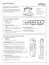
IRW-2PA WIRELESS RECEIVER PA
1. Powering the IRW-2PA
Turn on the IRW-2PA using the Power Switch (17) located inside the lockbox on
the lower right panel. When powered on, the Ch A and Ch B IR Reception LED In-
dicators (6) will light green if the corresponding transmitters are on and red when
the transmitters are off. Turn off the IRW-2PA when not charging or in use.
2. Inputs
The IRW-2PA has two additional inputs allowing for up to four audio signals to be
heard simultaneously when used with the wireless transmitters. An external line-level
device such as a CD/MP3-player, VCR audio, tape deck, or keyboard can be added
to the mix using the Aux Input (4) 1⁄4” jack. A hardwired microphone can be
plugged into the Mic Input (5) 1⁄4” unbalanced jack. This input can also be used
for other low-level audio signals, however, be careful to avoid input distortion by
turning down the volume of the external device.
3. Adjusting the Audio
The Channel A and B mix is dependent on the separate Channel A and B Volume
Controls (7). These should be adjusted to balance the audio from the channel A
and B microphones. The Aux Volume (8) and Mic Volume (9) can also be ad-
justed to balance the levels from those sources. Turn all volume controls down before
turning on the transmitters, or connecting any audio devices, to avoid loud noise or
feedback that can damage your speakers.
4. EQ
The Bass (10) and Treble (11) controls can be adjusted to cut or boost up to 12dB
of gain at 100Hz and 8KHz respectively. These controls affect the master mix. Add
warmth to vocals by turning the bass control to the right. Turn to the left to reduce
boomy vocals or to improve a mushy sound. Increase the treble control to boost high
frequencies, adding crispness too the audio. Turn to the left to cut these frequencies,
reducing sibilance and possible feedback.
5. Charger
The IRW-2PA can recharge the NiMH batteries for two transmitters simultaneously.
Simply turn on the battery charger by switching on the Battery Charging Power
Switch (14) and select the types of transmitters that are to be recharged using the
Battery Charging Selector Switch (16).
Transmitters Selector Switch
2x Bodypack Transmitters 2x LT
2x Handheld Transmitters 2x HT
1x Bodypack and 1x Handheld HT & LT
Place the handheld microphones directly into the Handheld Microphone Hold-
ers (12) and/or connect the bodypack transmitters using the Bodypack Charging
Connector (13). When the charger is connected, the corresponding IRW-2PA Bat-
tery Charging LED Indicator (15) will light brightly red. The LED indicator will
light green when the batteries are fully charged. Turn the battery charger off when
the transmitters are fully charged, being stored, or being used.
Note: The IRW-2PA is equipped with unique charger protection circuitry which
detects and shuts down if you attempt to charge alkaline or other non rechargeable
batteries. This is important because charging non rechargeable batteries can result
in re or explosion and should never be attempted.
IRW-2PA WIRELESS RECEIVER PA
FRONT
TOP
(1) Infrared Sensor Inputs
(2) Speaker Outputs
(1)
(7)
(2)
(5)
(16)
(18)
(3)
(14)
(15)
(4)
(10) (11) (8) (9)
(6)
(12)
(3) AC Power Inputs
(4) Aux Input
(5) Mic Input
(6) IR Reception LED Indicators
(7) Channel A and B Volume Controls
(8) Aux Volume
(9) Mic Volume
(10) Bass
(11) Treble
(12) Handheld Microphone Holders
(13) Bodyjack Charging Connectors
(14) Battery Charging Power Switch
(15) Battery Charging LED Indicators
(16) Battery Charging Selector Switch
(17) Power Switch
(18) Fuse
(13)
(17)
/