Copyright © 2012 Linear LLC 218940 B
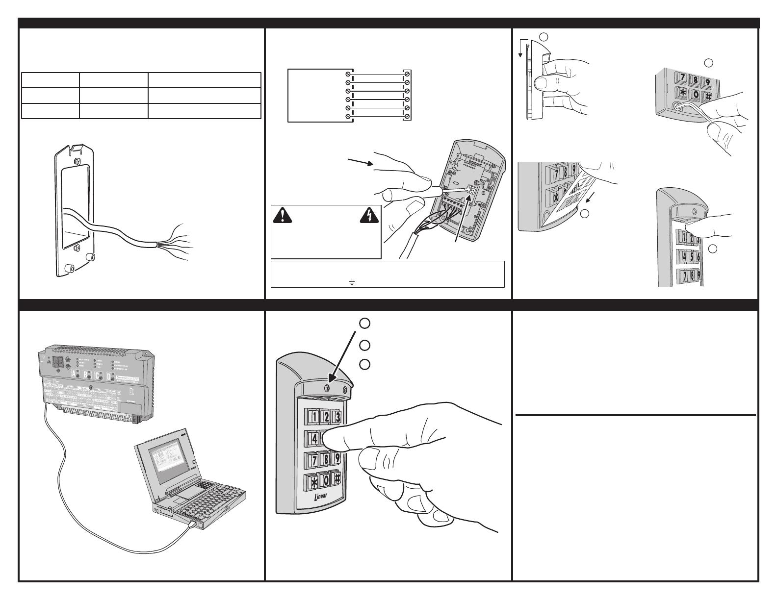
6. ROUTE THE CABLE 7. CONNECT THE CABLE & SET THE DEVICE ADDRESS 8. MOUNT THE KEYPAD
9. PROGRAM THE SYSTEM 10. TEST THE KEYPAD LINEAR LIMITED WARRANTY
This Linear product is warranted against defects in material and workmanship for twelve
(12) months. This warranty extends only to wholesale customers who buy direct from Linear
or through Linear’s normal distribution channels. Linear does not warrant this product to
consumers. Consumers should inquire from their selling dealer as to the nature of the dealer’s
warranty, if any. There are no obligations or liabilities on the part of Linear LLC for consequential
damages arising out of or in connection with use or performance of this product or other indirect damages
with respect to loss of property, revenue, or profi t, or cost of removal, installation, or reinstallation. All
implied warranties, including implied warranties for merchantability and implied warranties
for fi tness, are valid only until the warranty expires. This Linear LLC Warranty is in lieu of all other
warranties express or implied.
All products returned for warranty service require a Return Product Authorization Number
(RPA#). Contact Linear Technical Services at 1-800-421-1587 for an RPA# and other
important details.
FCC NOTICE
Changes or modifi cations not expressly described in this manual or approved by the
manufacturer could void the user’s authority to operate the equipment.
This equipment has been tested and found to comply with the limits for a Class B digital
device, pursuant to Part 15 of the FCC Rules. These limits are designed to provide reasonable
protection against harmful interference in a residential installation. This equipment generates,
uses and can radiate radio frequency energy and, if not installed and used in accordance with
the instructions, may cause harmful interference to radio communications. However, there
is no guarantee that interference will not occur in a particular installation. If this equipment
does cause harmful interference to radio or television reception, which can be determined by
turning the equipment off and on, the user is encouraged to try to correct the interference by
one or more of the following measures:
• Reorient or relocate the receiving antenna.
• Increase the separation between the equipment and receiver.
• Connect the equipment into an outlet on a circuit different from that to which the receiver is connected.
• Consult the dealer or an experienced radio/TV technician for help.
EACH AM-KPI KEYPAD EQUALS 9 LOAD UNITS
CABLE LENGTH FORMULA FOR EACH KEYPAD USED IN THE SYSTEM
CABLE RUN CABLE TYPE
FORMULA
300 FEET MAXIMUM BELDEN 9931 (24 AWG) FEET x LOAD UNITS < 3,000 MAXIMUM
500 FEET MAXIMUM WEICO 9405 (20 AWG) FEET x LOAD UNITS < 10,000 MAXIMUM
(1000 FEET WIRE MAXIMUM
ALLOWED IN THE SYSTEM)
HOMERUN WIRE FROM THE
CONTROLLER TO EACH
KEYPAD’S LOCATION
TO PROTECT THE KEYPAD FROM
STATIC DISCHARGES, BE SURE
EARTH GROUND IS CONNECTED
TO THE CONTROLLER
CAUTION
FOR LOCAL POWER, DISCONNECT RED WIRE FROM "PWR" CONNECTION ON AM-KPI
AND CONNECT EXTERNAL 12 VDC POWER SUPPLY (+ TO PWR & - TO GND)
NOTE: CONTROLLER MUST STILL BE CONNECTED TO AM-KPI "GND"
SET THE DEVICE
ADDRESS SWITCH
EACH REMOTE DEVICE
MUST BE SET TO A
UNIQUE NUMBER
FROM 1 TO 6
ARROW ON SWITCH SLOT
POINTS TO THE NUMBER
FOLLOW THIS WIRING DIAGRAM
TO CONNECT THE KEYPAD
TO THE CONTROLLER
AM-KPI
TERMINALS
PCLK
DVAL
DAT0
DAT1
GND
PWR
GND
DAT1
DAT0
DVAL
PCLK
PWR
ACCESS CONTROL
SYSTEM PBUS
TERMINALS
HOOK THE KEYPAD ASSEMBLY
ONTO THE MOUNTING PLATE
1
2
INSTALL THE
TWO SCREWS
3
FIT THE BOTTOM TAB OF
THE FACEPLATE INTO THE
SLOT ON THE KEYPAD
4
SNAP THE TOP
OF THE KEYPAD
INTO PLACE
PROGRAM THE CONTROLLER
TO CONFIGURE THE PBUS
DEVICE
REFER TO THE CONTROLLER
PROGRAMMING INSTRUCTIONS
FOR DETAILS
1
2
3
THE RED INDICATOR
SHOULD BE LIT
ENTER A VALID CODE
THE RED INDICATOR SHOULD TURN
GREEN AND THE PROGRAMMED
RELAY IN THE CONTROLLER
SHOULD ACTIVATE
THE YELLOW INDICATOR LIGHTS WHEN
THE KEYPAD IS LOCKED OUT OR BUSY
PRINTER’S INSTRUCTIONS:
INSTR,INSTL,AM-KPI - LINEAR P/N: 218940 B - INK: BLACK - MATERIAL: 20 LB. MEAD BOND - SIZE: 11.000” X 8.500” - SCALE: 1-1 - SIDE 2 OF 2


