HealthRider HRTL89406.0 User manual
- Category
- Treadmills
- Type
- User manual

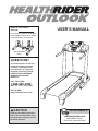
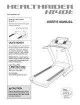
USER'S MANUAL
CAUTION
Read all precautions and instruc
-
tions in this manual before using
this equipment. Save this manual
for future reference.
Serial Number
Decal
Model No. HRTL89406.0
Serial No.
Find the serial number in the location
shown below. Write the serial number
in the space above for reference.
Visit our website at
www.healthrider.com
new products, prizes,
fitness tips, and much more!
V
QUESTIONS?
As a manufacturer, we are com-
mitted to providing complete
customer satisfaction. If you
have questions, or if parts are
damaged or missing, PLEASE
CONTACT OUR CUSTOMER
SERVICE DEPARTMENT
DIRECTLY.
CALL TOLL-FREE:
1-888-922-4222
Mon.–Fri., 6 a.m.–6 p.m. MST
ON THE WEB:
www.healthriderservice.com

TABLE OF CONTENTS
IMPORTANT PRECAUTIONS . . . . . . . . . . . . . . . . . . . . . . . . . . . . . . . . . . . . . . . . . . . . . . . . . . . . . . . . . . . . . . . . .3
BEFORE YOU BEGIN . . . . . . . . . . . . . . . . . . . . . . . . . . . . . . . . . . . . . . . . . . . . . . . . . . . . . . . . . . . . . . . . . . . . . . .6
ASSEMBLY . . . . . . . . . . . . . . . . . . . . . . . . . . . . . . . . . . . . . . . . . . . . . . . . . . . . . . . . . . . . . . . . . . . . . . . . . . . . . . .7
HOW TO USE THE CHEST PULSE SENSOR . . . . . . . . . . . . . . . . . . . . . . . . . . . . . . . . . . . . . . . . . . . . . . . . . . .11
OPERATION AND ADJUSTMENT . . . . . . . . . . . . . . . . . . . . . . . . . . . . . . . . . . . . . . . . . . . . . . . . . . . . . . . . . . . .12
HOW TO FOLD AND MOVE THE TREADMILL . . . . . . . . . . . . . . . . . . . . . . . . . . . . . . . . . . . . . . . . . . . . . . . . . .25
TROUBLESHOOTING . . . . . . . . . . . . . . . . . . . . . . . . . . . . . . . . . . . . . . . . . . . . . . . . . . . . . . . . . . . . . . . . . . . . . .26
CONDITIONING GUIDELINES . . . . . . . . . . . . . . . . . . . . . . . . . . . . . . . . . . . . . . . . . . . . . . . . . . . . . . . . . . . . . . .29
PART LIST . . . . . . . . . . . . . . . . . . . . . . . . . . . . . . . . . . . . . . . . . . . . . . . . . . . . . . . . . . . . . . . . . . . . . . . . . . . . . . .30
ORDERING REPLACEMENT PARTS . . . . . . . . . . . . . . . . . . . . . . . . . . . . . . . . . . . . . . . . . . . . . . . . . . . . . . . . . .31
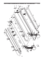
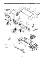
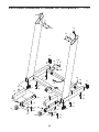
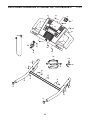
EXPLODED DRAWING . . . . . . . . . . . . . . . . . . . . . . . . . . . . . . . . . . . . . . . . . . . . . . . . . . . . . . . . . . . . . . . . . . . . .32
LIMITED WARRANTY . . . . . . . . . . . . . . . . . . . . . . . . . . . . . . . . . . . . . . . . . . . . . . . . . . . . . . . . . . . . . . .Back Cover
HealthRider is a registered trademark of ICON IP, Inc.
2

1. It is the responsibility of the owner to ensure
t
hat all users of this treadmill are adequately
informed of all warnings and precautions.
2. Use the treadmill only as described.
3. Place the treadmill on a level surface, with at
least eight feet of clearance behind it and two
feet on each side. Do not place the treadmill
on any surface that blocks air openings. To
protect the floor or carpet from damage, place
a mat under the treadmill.
4. Keep the treadmill indoors, away from mois-
ture and dust. Do not put the treadmill in a
garage or covered patio, or near water.
5. Do not operate the treadmill where aerosol
products are used or where oxygen is being
administered.
6. Keep children under the age of 12 and pets
away from the treadmill at all times.
7. The treadmill should not be used by persons
weighing more than 325 pounds.
8. Never allow more than one person on the
treadmill at a time.
9. Wear appropriate exercise clothes when
using the treadmill. Do not wear loose clothes
that could become caught in the treadmill.
Athletic support clothes are recommended for
both men and women.
Always wear athletic
shoes. Never use the treadmill with bare feet,
wearing only stockings, or in sandals.
10. When connecting the power cord (see page 12),
plug the power cord into a surge suppressor
(not included) and plug the surge suppressor
into a grounded circuit capable of carrying 15
or more amps. No other appliance should be on
the same circuit. Do not use an extension cord.
11. Use only a single-outlet surge suppressor that
meets all of the specifications described on
page 12. To purchase a surge suppressor, see
your local HealthRider dealer or call the toll-
free telephone number on the front cover of
this manual and order part number 146148, or
see your local electronics store.
12. Failure to use a properly functioning surge
s
uppressor could result in damage to the con-
trol system of the treadmill. If the control sys-
tem is damaged, the walking belt may change
speed, accelerate, or stop unexpectedly,
which may result in a fall and serious injury.
13. Keep the power cord and the surge suppres-
sor away from heated surfaces.
14. Never move the walking belt while the power
is turned off. Do not operate the treadmill if
the power cord or plug is damaged, or if the
treadmill is not working properly. (See
TROUBLESHOOTING on page 26 if the tread-
mill is not working properly.)
15. Read, understand, and test the emergency
stop procedure before using the treadmill (see
HOW TO TURN ON THE POWER on page 14).
16. Never start the treadmill while you are stand-
ing on the walking belt. Always hold the
handrails while using the treadmill.
17. The treadmill is capable of high speeds.
Adjust the speed in small increments to avoid
sudden jumps in speed.
18. The pulse sensors are not a medical devices.
Various factors, including the user's move-
ment, may affect the accuracy of heart rate
readings. The pulse sensors are intended
only as an exercise aid in determining heart
rate trends in general.
19. Never leave the treadmill unattended while it
is running. Always remove the key, unplug the
power cord, and switch the reset/off circuit
breaker to the “off” position when the tread
-
mill is not in use. (See the drawing on page 6
for the location of the reset/off circuit breaker.)
20. Do not attempt to raise, lower, or move the
treadmill until it is properly assembled. (See
ASSEMBLY on page 7, and HOW TO FOLD
AND MOVE THE TREADMILL on page 25.) You
must be able to safely lift 45 pounds (20 kg) to
raise, lower, or move the treadmill.
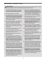
WARNING: To reduce the risk of burns, fire, electric shock, or injury to persons, read the
following important precautions and information before operating the treadmill.
IMPORTANT PRECAUTIONS
3

21. Do not change the incline of the treadmill by
p
lacing objects under the treadmill.
22. When folding or moving the treadmill, make
sure that the frame is held securely by the pin
o
n the latch knob.
23. Inspect and properly tighten all parts of the
t
readmill regularly.
24. Never insert or drop any object into any
opening.
25.
DANGER: Always unplug the power
cord immediately after use, before cleaning
the treadmill, and before performing the main-
tenance and adjustment procedures de-
scribed in this manual. Never remove the
motor hood unless instructed to do so by an
authorized service representative. Servicing
other than the procedures in this manual
should be performed by an authorized service
representative only.
26. The treadmill is intended for in-home use
only. Do not use the treadmill in any commer-
cial, rental, or institutional setting.
27. If an outside antenna or cable system is con-
nected, be sure that the antenna or cable sys-
tem is grounded to provide some protection
against voltage surges and built-up static
charges. Section 810 of the National
Electrical Code, ANSI/NFPA No. 70-1984, pro-
vides information with respect to proper
grounding of the mast and supporting struc-
ture, grounding of the lead-in wire to an an-
tenna discharge unit, size of grounding con-
ductors, location of antenna discharge unit,
connection to grounding electrodes, and re-
quirements for the grounding electrode.
28. An outside antenna system should not be lo-
cated in the vicinity of overhead power lines
or other electric light or power circuits, or
w
here it can fall into such power lines or cir-
c
uits. When installing an outside antenna sys-
tem, extreme care should be taken to keep
from touching such power lines or circuits, as
contact with them might be fatal.
29. To reduce the risk of electric shock, do not re-
move the cover or the back of the television.
There are no user serviceable parts inside.
Refer servicing to qualified service personnel.
30. Upon completion of any service or repairs to
the treadmill or the television, ask the service
technician to perform safety checks to con-
firm that the unit is in proper operating con-
dition.
• Use No. 10 AWG (5.3mm
2
) copper, No. 8
AWG (8.4mm
2
) aluminum, No. 17 AWG
(1.0mm
2
) copper-clad steel or bronze wire,
or larger as a ground wire.
• Secure an antenna lead-in and ground wires
to the house with stand-off insulators
spaced from 4 to 6 feet (1.22 to 1.83m)
apart.
• Mount an antenna discharge unit as close
as possible to where the lead-in enters the
house.
• Use a jumper wire not smaller than No. 6
AWG (13.3mm
2
) copper, or the equivalent
when a separate antenna-grounding elec-
trode is used. See NEC Section 810-21 (j).
Note to CATV system installer: This reminder is
provided to call the CATV system installer’s at-
tention to Article 820-40 of the NEC that provides
guidelines for proper grounding and, in particu
-
lar, specifies that the cable ground shall be con-
nected to the grounding system of the building,
as close to the point of cable entry as practical.
4

5
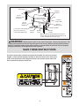
The decals shown here have been placed on the treadmill. If a decal is missing or
illegible, call the toll-free telephone number on the front cover of this manual and
order a free replacement decal. Apply the decal in the location shown. Note: The
decals may not be shown at actual size.
WARNING: Before beginning this or any exercise program, consult your physician. This
is especially important for persons over the age of 35 or persons with pre-existing health problems.
Read all instructions before using. ICON assumes no responsibility for personal injury or property
damage sustained by or through the use of this product.
SAVE THESE INSTRUCTIONS
Power Lines
Ground
Clamps
Ground
Clamps
Ground
Clamp
Bonding
Jumper
Standoff
Insulators
Antenna
L
ead-in Wire
Ground Wire
Ground
W
ire
A
ntenna
Discharge Unit
T
o External Antenna
Terminal of Treadmill
Mast
Service
Entrance
Equipment
Power Service Grounding
Electrode System (e.g.
Interior Metal Water Pipe)
Service
E
ntrance
Conductors
Optional Antenna Grounding Electrode Driven 8
Feet (2.44m) Into The Earth (If Required By Local
Codes). See NEC Section 810–21 (f).

6
Thank you for selecting the revolutionary HealthRider
®
O
UTLOOK treadmill. The OUTLOOK treadmill offers
an impressive selection of features designed to make
your workouts at home more enjoyable and effective.
And when you’re not exercising, the unique OUTLOOK
t
readmill can be folded up, requiring less than half the
floor space of other treadmills.
For your benefit, read this manual carefully before
using the treadmill
. If you have questions after read-
ing this manual, please see the front cover of this man-
u
al. To help us assist you, please note the product
model number and serial number before contacting us.
The model number of the treadmill is HRTL89406.0.
The serial number can be found on a decal attached to
t
he treadmill (see the front cover of this manual for the
location).
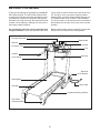
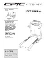
Before reading further, please familiarize yourself with
the parts that are labeled in the drawing below.
BEFORE YOU BEGIN
Handrail
Console
Fan
Personal Television
Book Holder
Key/Clip
Reset/Off
Circuit Breaker
Walking Belt
Foot Rail
Power Cord
Cushioned Walking Platform
Rear Roller
Adjustment Bolts
Accessory Tray
Speaker
Pulse Sensor

ASSEMBLY
A
ssembly requires two persons.
S
et the treadmill in a cleared area and remove all packing materials.
D
o not
dispose of the packing materials until assembly is completed.
Note: The underside of the treadmill walking belt is coated with high-performance lubricant. During shipping, a
small amount of lubricant may be transferred to the top of the walking belt or the shipping carton. This is a normal
condition and does not affect treadmill performance. If there is lubricant on top of the walking belt, simply wipe off
the lubricant with a soft cloth and a mild, non-abrasive cleaner.
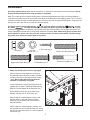
Assembly requires the included hex key and your own phillips screwdriver , and rub-
ber mallet . For help identifying the assembly hardware, see the drawings below.
The number
in parentheses below each drawing is the key number of the part, from the PART LIST on pages 30 and 31. The
number following the parentheses is the quantity needed for assembly.
Note: Some small parts may have been
preassembled. If a part is not in the parts bag, check to see if it has been preassembled. To avoid damag-
ing plastic parts, do not use power tools for assembly.
1” Tek Screw (82)–4
3/8” Star
Washer (71)–4
Nut (20)–2
Extension Leg Bolt (87)–4
Console Bolt (72)–4
Upper Latch Shock Bolt (4)–1
Lower Latch Shock Bolt (3)–1
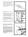
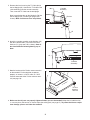
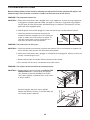
1. Make sure that the power cord is unplugged.
With the help of a second person, carefully
tip
the treadmill onto its left side as shown. Partially
fold the Frame (55) so that the treadmill is more
stable.
Do not fully fold the Frame until the
treadmill is completely assembled.
Insert an Extension Leg (97) into the base of the
Uprights (85) as shown. Tighten two Extension Leg
Bolts (87) into the bottom of the Extension Leg.
Attach two Base Pads (81) to the base of the
Uprights (85) with two 1” Tek Screws (82).
With the help of a second person, tip the tread-
mill over onto it’s right side. Attach the other
Extension Leg and Base Pads (not shown) as
described above.
With the help of a second person, carefully
raise
the treadmill so that all four Base Pads (81) are on
the floor and the Frame (55) is in a vertical position
(see drawing 3).
97
85
55
87
82
81
81
1
7

8
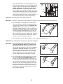
4. Remove the band securing the Upright Wire
Harness (73) to the right Upright (85). Have a
second person hold the console assembly near
the right Upright.
Connect the Upright Wire Harness (73) to the wire
harness extending from the console assembly.
Make sure to connect the connectors prop-
erly (see the inset drawing). The connectors
should slide together easily and snap into
place.
If the connectors do not slide together
easily and snap into place, turn one connector
and try again.
IF THE CONNECTORS ARE NOT
CONNECTED PROPERLY, THE CONSOLE
MAY BE DAMAGED WHEN THE POWER IS
TURNED ON.
Then, insert the connectors into
the right Upright (85).
73
85
Console
Assembly
73
4
3. Remove the plastic ties from the ends of the
Latch Assembly (76).
Hold the Latch Assembly with the large barrel
and knob positioned as shown; make sure all of
the holes are aligned (see the inset drawings).
Next, attach the lower end of the Latch
Assembly to the bracket on the Upright (85) with
the Lower Latch Bolt (3) and a Nut (20).
Then, attach the upper end of the Latch
Assembly (76) to the bracket on the Frame (55)
with the Upper Latch Bolt (4) and a Nut (20).
Note: It may be necessary to move the Frame
back and forth to align the Latch Assembly with
the Bracket.
Lower the treadmill frame (see HOW TO LOWER
THE TREADMILL FOR USE on page 25).
76
20
20
Large
Barrel
85
3
55
3
4
Knob
Top
Bottom
Holes
Holes
2. Identify the Latch Assembly (76). Make sure that
the sleeve has been slid over hole 1 and that the
k
nob is locked into hole 1. P
ull on the sleeve
to make sure it is locked into place.
Next, make sure that the knob (46) is locked into
hole 2. If it is not, pull out the tube until you see
hole 2 and then slide the tube back in until the
k
nob locks into hole 2.
2
Knob
Sleeve
Hole 1
Hole 2
Tube
76

9
6. Attach the console assembly to the Uprights (85)
with four Console Bolts (72) and four 3/8” Star
Washers (71) (only one side is shown).
Start all
four Console Bolts before tightening any of
them.
71
72
85
Console
Assembly
6
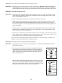
7. Note the location of the 75 ohm antenna terminal
on the treadmill. For the television to operate
properly, an antenna, a CATV cable, or a VCR
must be connected to the 75 ohm antenna termi-
nal (see page 10).
7
8. Make sure that all parts are properly tightened before you use the treadmill. Keep the included hex key
in a secure place; the hex key is used to adjust the walking belt (see page 27).
To protect the floor or carpet
from damage, place a mat under the treadmill.
5. Remove the band securing the TV Cable (63) to
t
he left Upright (85). Connect the TV Cable to the
cable extending from the console assembly.
Then, insert the TV Cable into the left Upright.
Next, insert the brackets on the Handrails (70) into
the left Upright (85) and the right Upright (not
shown).
Make sure that no wires are pinched.
63
70
B
racket
85
Console
Assembly
5
75 Ohm
Antenna
Terminal

10
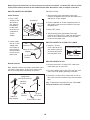
HOW TO CONNECT AN ANTENNA
Indoor Antenna
1. Place a VHF
antenna in the
desired loca-
tion. Connect
the 300 ohm
flat wire from
the antenna to
a 300 ohm to
75 ohm
adapter.
2. Push the 300
ohm to 75 ohm
adapter onto
the 75 ohm an-
tenna terminal
on the treadmill
frame near the
power cord.
Outdoor Antenna
Note: Outdoor antennas are subject to weathering that
can reduce signal quality. Inspect your antenna and
the lead-in wiring before connecting the antenna.
300 Ohm Flat Wire
1. See the drawing near the bottom of this page.
Connect the 300 ohm flat wire from the antenna to a
300 ohm to 75 ohm adapter.
2. Push the 300 ohm to 75 ohm adapter onto the 75
ohm antenna terminal on the treadmill frame near
the power cord.
75 Ohm CATV Cable
1. See the drawing near the bottom of this page.
Connect the 75 ohm CATV cable from the antenna
to the 75 ohm antenna terminal on the treadmill
frame near the power cord.
HOW TO CONNECT A 75 OHM CATV CABLE
1. Connect a 75 ohm
CATV cable to the 75
ohm antenna terminal
on the treadmill frame
near the power cord.
HOW TO CONNECT A VCR
1. Connect one end of a 75 ohm CATV cable to the
video output jack on your VCR.
2. Plug in the power cord of your VCR. See your VCR
user’s manual for proper grounding instructions.
3. Connect the 75 ohm CATV cable to the 75 ohm an-
tenna terminal on the treadmill frame near the power
cord.
Note: To operate the television with your VCR, make
sure that channel 3 or 4 is selected.
75 Ohm
Terminal
300 to 75 Ohm
Adapter
VHF
Antenna
300 to 75 Ohm Adapter
S
crewdriver
VHF 300
Ohm Flat
Wire
Combination
VHF/UHF Antennas
300 Ohm
Flat Wire
75 Ohm
Terminal
300 to 75
Ohm Adapter
75 Ohm
CATV Cable
75 Ohm CATV Cable
75 Ohm Terminal
75 Ohm CATV Cable
Before the personal television can be used, you must connect an antenna, a 75 ohm CATV cable, or a VCR
to the 75 ohm antenna terminal on the treadmill frame. Note: No antenna, cable, or adapter is included.

1
1
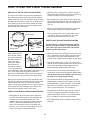
H
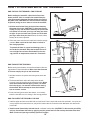
OW TO PUT ON THE CHEST PULSE SENSOR
T
he chest pulse sensor consists of two components:
the chest strap and the sensor unit (see the drawing
below). Insert the tab on one end of the chest strap into
the hole in one end of the sensor unit, as shown in the
inset drawing. Press the end of the sensor unit under
the buckle on the chest strap. The tab should be flush
with the front of the sensor unit.
Next, wrap the chest
pulse sensor around
your chest and attach
the other end of the
chest strap to the
sensor unit. Adjust
the length of the
chest strap, if neces-
sary. The chest pulse
sensor should be under your clothes, tight against your
skin, and as high under the pectoral muscles or
breasts as is comfortable. Make sure that the logo on
the sensor unit is facing forward and is right-side-up.
Next, pull the sensor unit away from your body a few
inches and locate the two electrode areas on the inner
side (the electrode areas are covered by shallow
ridges). Using saline solution such as saliva or contact
lens solution, wet both electrode areas. Return the
sensor unit to a position against your chest.
CHEST PULSE SENSOR CARE AND MAINTENANCE
• Thoroughly dry the chest pulse sensor after each
use. The chest pulse sensor is activated when the
electrode areas are wetted and the heart rate
monitor is put on; the chest pulse sensor shuts off
when it is removed and the electrode areas are
dried. If the chest pulse sensor is not dried after
each use, it may remain activated longer than nec-
essary, draining the battery prematurely.
•
Store the chest pulse sensor in a warm, dry place.
Do not store the chest pulse sensor in a plastic bag
o
r other container that may trap moisture.
• Do not expose the chest pulse sensor to direct sun-
l
ight for extended periods of time; do not expose it to
temperatures above 120° F (50° C) or below 15° F
(-10° C).
• Do not excessively bend or stretch the sensor unit
when using or storing the chest pulse sensor.
• Clean the sensor unit using a damp cloth—never
use alcohol, abrasives, or chemicals. The chest
strap may be hand washed and air dried.
CHEST PULSE SENSOR TROUBLESHOOTING
The instructions on the following pages explain
how the chest pulse sensor is used with the con-
sole. If the chest pulse sensor does not function
properly, try the steps below.
• Make sure that you are wearing the chest pulse sen-
sor as described at the left. Note: If the chest pulse
sensor does not function when positioned as de-
scribed, move it slightly lower or higher on your chest.
• Use saline solution such as saliva or contact lens
solution to wet the two electrode areas on the sensor
unit. If heart rate readings do not appear until you
begin perspiring, rewet the electrode areas.
• As you walk or run on the treadmill, position your-
self near the centre of the walking belt. For the con-
sole to display heart rate readings, the user must
be within arm’s length of the console.
•
The chest pulse sensor is designed to work with
people who have normal heart rhythms. Heart rate
reading problems may be caused by medical condi-
tions such as premature ventricular contractions
(pvcs), tachycardia bursts, and arrhythmia.
• The operation of the chest pulse sensor can be af-
fected by magnetic interference caused by high
power lines or other sources. If it is suspected that
this is a problem, try relocating the treadmill.
• The CR2032 battery may need to be replaced (see
page 28).
Chest Strap
Tabs
Sensor Unit
Tab
Sensor
Unit
Buckle
HOW TO USE THE CHEST PULSE SENSOR

12
OPERATION AND ADJUSTMENT
T
HE PRE-LUBRICATED WALKING BELT
Your treadmill features a walking belt coated with high-
performance lubricant. IMPORTANT: Never apply sil-
i
cone spray or other substances to the walking
b
elt or the walking platform. Such substances will
deteriorate the walking belt and cause excessive
wear.
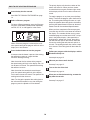
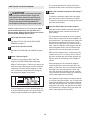
HOW TO PLUG IN THE POWER CORD
Your treadmill, like any other type of sophisticated
electronic equipment, can be seriously damaged by
sudden voltage changes in your home’s power.
Voltage surges, spikes, and noise interference can
result from weather conditions or from other appliances
being turned on or off. To decrease the possibility of
your treadmill being damaged, always use a surge
suppressor with your treadmill (see drawing 1 at
the right). To purchase a surge suppressor, see
your local HealthRider dealer or call the toll-free
telephone number on the front cover of this man-
ual and order part number 146148, or see your local
electronics store.
Use only a single-outlet surge suppressor that is
UL 1449 listed as a transient voltage surge sup-
pressor (TVSS). The surge suppressor must have a
UL suppressed voltage rating of 400 volts or less
and a minimum surge dissipation of 450 joules.
The surge suppressor must be electrically rated for
120 volts AC and 15 amps. There must be a moni-
toring light on the surge suppressor to indicate
whether it is functioning properly. Failure to use a
properly functioning surge suppressor could result
in damage to the control system of the treadmill. If
the control system is damaged, the walking belt
may change speed, accelerate, or stop unexpect-
edly, which may result in a fall and serious injury.
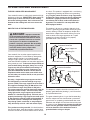
This product must be grounded.
If it should malfunc
-
tion or break down, grounding provides a path of least
resistance for electric current to reduce the risk of elec
-
t
ric shock. This product is equipped with a cord having
an equipment-grounding conductor and a grounding
plug.
Plug the power cord into a surge suppressor,
and plug the surge suppressor into an appropriate
o
utlet that is properly installed and grounded in
a
ccordance with all local codes and ordinances.
Important: The treadmill is not compatible with
GFCI-equipped outlets.
This product is for use on a nominal 120-volt circuit,
and has a grounding plug that looks like the plug illus-
trated in drawing 1 below. A temporary adapter that
looks like the adapter illustrated in drawing 2 may be
used to connect the surge suppressor to a 2-pole
receptacle as shown in drawing 2 if a properly
grounded outlet is not available.
The temporary adapter should be used only until a
properly grounded outlet (drawing 1) can be installed
by a qualified electrician.
The green-colored rigid ear, lug, or the like extending
from the adapter must be connected to a permanent
ground such as a properly grounded outlet box cover.
Whenever the adapter is used it must be held in place
by a metal screw.
Some 2-pole receptacle outlet box
covers are not grounded. Contact a qualified elec-
trician to determine if the outlet box cover is
grounded before using an adapter.
DANGER: Improper connection
of the equipment-grounding conductor can
result in an increased risk of electric shock.
Check with a qualified electrician or service-
man if you are in doubt as to whether the
product is properly grounded. Do not modify
the plug provided with the product—if it will
not fit the outlet, have a proper outlet
installed by a qualified electrician.
1
2
Grounded Outlet Box
Grounded Outlet Box
Grounding Plug
Surge Suppressor
Surge Suppressor
Grounding Pin
Adapter
Lug
Metal Screw
Grounded Outlet
Grounding Pin

13
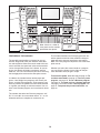
FEATURES OF THE CONSOLE
The treadmill console offers an impressive array of
features designed to make your workouts more effec-
tive and enjoyable. When the manual mode of the con-
sole is selected, the speed and incline of the treadmill
can be changed with the touch of a button. As you ex-
ercise, the console will display continuous exercise
feedback. You can even measure your heart rate using
the handgrip pulse sensor or the chest pulse sensor.
In addition, the console features twelve preset pro-
grams—four Weight Loss programs, four Fitness pro
-
grams, and four Incline programs. Each program auto-
matically controls the speed and incline of the treadmill
as it guides you through an effective workout. You can
even create Custom programs and save them for future
use.
The console also offers four Distance programs—2K,
5K, 7K, and 10K—that count down from 2, 5, 7, or 10
kilometers while you complete an endurance run.
The console also offers four Pulse programs that con-
trol the speed and incline of the treadmill to help you
keep your heart rate near target heart rate settings.
Note: The Pulse programs require the use of the chest
pulse sensor.
Whether you select the manual mode or a program,
you can enjoy the shows of your choice on the per-
sonal television while you get in shape.
To turn on the power, follow the steps on page 14. To
use the manual mode, see page 14. To use a preset
program, see page 16. To use a Distance program,
see page 18. To create and use a Custom program,
see pages 19 and 20. To use a Pulse program, see
page 21. To operate the personal television, see
page 23.
Note: If there is a sheet of
clear plastic on the console,
peel off the clear plastic.

14
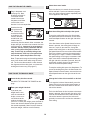
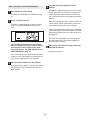
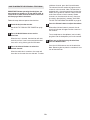
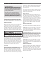
H
OW TO TURN ON THE POWER
Plug in the power cord
(see page 12). Next,
l
ocate the reset/off cir-
cuit breaker on the
treadmill frame near
the power cord. Make
sure that the circuit
breaker is in the reset position.
Stand on the foot
rails of the tread-
mill. Find the clip
attached to the key,
and slide the clip
securely onto the
waistband of your
clothes. Next, in-
sert the key into the console. After a moment, the
display will light, and after a few seconds, the tele-
vision will turn on.
Important: In an emergency
situation, the key can be pulled from the con-
sole, causing the walking belt to slow to a
stop. Test the clip by carefully taking a few
steps backward; if the key is not pulled from
the console, adjust the position of the clip.
Note: To prevent damage to the walking platform,
wear clean athletic shoes while using the tread-
mill. The first time the treadmill is used, observe
the alignment of the walking belt, and center the
walking belt if necessary (see page 27).
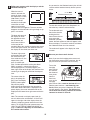
HOW TO USE THE MANUAL MODE
Insert the key into the console.
See HOW TO TURN ON THE POWER on this
page.
Enter your weight if desired.
If you enter your
weight into the con-
sole, the console will
display a more accu-
rate estimate of the
number of calories that
you burn. To enter your weight, press the Enter in-
crease and decrease buttons on the right side of
the console repeatedly. Note: Once you have en-
tered your weight, it will be saved in memory.
Select the manual mode.
Each time the key is inserted, the manual mode
w
ill be selected. If you have selected a program,
press any of the program buttons repeatedly until
a track appears in the display.
Start the walking belt and adjust the speed.
To start the walking belt, press the Start button,
the Speed Control increase button, or one of the
numbered Speed buttons on the right side of the
console.
If the Start button or the Speed Control increase
button is pressed, the walking belt will begin to
move at 1 mph. As you exercise, change the
speed of the walking belt as desired by pressing
the Speed Control increase and decrease buttons.
Each time a button is pressed, the speed setting
will change by 0.1 mph; if a button is held down,
the speed setting will change in increments of 0.5
mph. If one of the numbered Speed buttons on
the right side of the console is pressed, the walk-
ing belt will gradually increase in speed until it
reaches the selected speed setting.
To stop the walking belt, press the Stop button. To
restart the walking belt, press the Start button, the
Speed Control increase button, or one of the num-
bered Speed buttons on the right side of the con-
sole.
Change the incline of the treadmill as desired.
To change the incline of the treadmill, press the
Power Incline increase and decrease buttons or
one of the numbered Incline buttons on the left
side of the console.
Each time the Power Incline increase or decrease
button is pressed, the incline will change by 0.5%.
If one of the numbered Incline buttons on the left
side of the console is pressed, the incline will
gradually increase until it reaches the selected in-
cline setting.
5
4
3
2
1
2
1
Key
Reset
Position
Clip

15
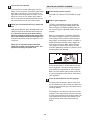
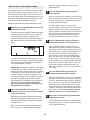
Follow your progress with the displays and the
Workout Intensity bar.
When the manual
m
ode is selected, the
matrix will show a track
that represents 1/4 mile
(400 meters). As you
w
alk or run on the
treadmill, the indicators
around the track will
appear in succession
until the entire track appears. The track will then
disappear and the indicators will again begin to ap-
pear in succession.
The lower left corner of
the display will show
the approximate num-
ber of calories you
have burned and the
incline level of the
treadmill. When you use the handgrip pulse sensor
or the chest pulse sensor, the lower left corner of
the display will also show your heart rate.
The lower right corner
of the display will show
the distance that you
have walked or run, the
elapsed time, your
pace (in minutes per
mile), and the speed of the walking belt. Note:
When a program is selected (except for a
Distance program or a Custom program), the
lower right corner of the display will show the time
remaining in the program instead of the elapsed
time.
The center of the dis-
play is the priority dis
-
play. Press the Display
(DISPL) button repeat-
edly until the priority
display shows the information that you want to
view. Note: While information is displayed in the
priority display, the same information will not be
displayed in the lower left or right corner of the dis-
play.
Note: The console can display speed and dis-
tance in either miles or kilometers. A “Km/H” will
appear in the right side of the display when the
console is displaying speed and distance in kilo-
meters. To change the unit of measurement, see
HOW TO USE THE INFORMATION MODE on
page 24.
Note: For simplicity, all instructions in
this section refer to miles.
As you exercise, the Workout Intensity bar will indi-
c
ate the relative workout intensity level of your ex-
ercise.
To reset the console, press the Stop button, re-
move the key, and then reinsert the key.
To see the total num-
ber of miles that the
walking belt has
moved since the last
reset, press the
Odometer (ODOM)
button; the total number of miles will appear in the
Distance display.
To reset this number, hold down
the Odometer button for a few seconds.
The number will appear in the display for a few
seconds.
Measure your heart rate if desired.
Note: If you use the handgrip pulse sensor and
the chest pulse sensor at the same time, the dis-
play will not show your heart rate accurately.
To use the
handgrip
pulse sensor,
first remove
the sheets of
clear plastic
from the
metal con-
tacts on the
handgrip
pulse sensor. Next,
stand on the foot rails and
hold the metal contacts—avoid moving your
hands. When your pulse is detected, your heart
rate will appear in the display. For the most ac
-
curate heart rate reading, continue to hold the
contacts for about 15 seconds.
7
6
Workout Intensity bar
Contacts

16
T
urn on the fan if desired.
To turn on the fan at low speed, press the Fan
button. To turn on the fan at medium speed, press
the button a second time. To turn on the fan at
h
igh speed, press the button a third time. To turn
off the fan, press the Fan button again. Note: If
the fan is on when the walking belt stops, the fan
will automatically turn off after a few minutes.
When you are finished exercising, remove the
key.
Step onto the foot rails, press the Stop button, and
adjust the incline of the treadmill to the lowest set-
ting.
The incline must be at the lowest setting
when the treadmill is folded to the storage posi-
tion or the treadmill will become damaged. Next,
remove the key from the console and put it in a se-
cure place.
When you are finished using the treadmill,
switch the reset/off circuit breaker to the “off”
position and unplug the power cord.
HOW TO USE A PRESET PROGRAM
Insert the key into the console.
S
ee HOW TO TURN ON THE POWER on page
14.
S
elect a preset program.
To select a preset program, press the Weight
Loss Programs (WT LOSS PGMS) button, the
Fitness Programs (FITNESS PGMS) button, or
the Incline Programs (INCLINE PGMS) button re-
peatedly.
When a preset program is selected, the display
will show the program number, the maximum in-
cline setting and the maximum speed setting of
the program, and the program time. In addition, a
profile of the speed settings of the program will
scroll across the matrix. Note: When a Weight
Loss program is selected, the display will also
show the approximate number of calories that will
be burned during the workout.
Each preset program is divided into several one-
minute segments. One speed setting and one in-
cline setting are programmed for each segment.
Note: The same speed setting and/or incline set-
ting may be programmed for two or more consec-
utive segments.
Press the Start button to start
the program.
A moment after the button is pressed, the tread-
mill will automatically adjust to the first speed and
incline settings of the program. Hold the handrails
and begin walking.
Each program is divided into several one-minute
segments. One speed setting and one incline set-
ting are programmed for each segment. Note: The
same speed setting and/or incline setting may be
programmed for two or more consecutive seg-
ments.
3
2
1
9
8

17
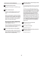
The speed setting for
t
he first segment will be
shown in the flashing
C
urrent Segment col-
umn of the matrix. (The
incline settings are not
shown in the matrix.)
T
he speed settings for
t
he next several seg-
ments will be shown in the columns to the right.
When only three seconds remain in the first seg-
ment of the program, both the Current Segment
column and the column to the right will flash and a
series of tones will sound. If the speed and/or in-
cline of the treadmill is about to change, the speed
setting and/or the incline setting will flash in the
display to alert you.
When the first segment is completed,
all speed
settings will move one column to the left
. The
speed setting for the second segment will then be
shown in the flashing Current Segment column
and the treadmill will automatically adjust to the
speed and incline settings for the second seg-
ment. Note: If all seven of the indicators in the
Current Segment column are lit,
the speed settings
may move downward
so that only the highest indi-
cators appear in the matrix.
The program will continue in this way until the
speed setting for the last segment is shown in the
Current Segment column and the last segment
ends. The walking belt will then slow to a stop.
If the speed and/or incline settings of the program
are too high or too low, you can override the set-
ting by pressing the Speed or Incline buttons;
however, when the next segment begins, the
t
readmill will automatically adjust to the speed
and incline settings for the next segment.
To stop the program at any time, press the Stop
button. To restart the program, press the Start but-
ton or the Speed Control increase button. The
w
alking belt will begin to move at 1 mph. When the
n
ext segment of the program begins, the treadmill
will automatically adjust to the speed and incline
settings for the next segment.
Follow your progress with the displays and the
Workout Intensity bar.
See step 6 on page 15.
Measure your heart rate if desired.
See step 7 on page 15.
Turn on the fan if desired.
See step 8 on page 16.
When you are finished exercising, remove the
key from the console.
When the program ends, make sure that the in-
cline of the treadmill is at the lowest setting.
Next, remove the key from the console and put it in
a safe place.
When you are finished using the treadmill,
switch the reset/off circuit breaker to the “off”
position and unplug the power cord.
7
6
5
4
C
urrent Segment

18
HOW TO USE A DISTANCE PROGRAM
Insert the key into the console.
S
ee HOW TO TURN ON THE POWER on page
14.
Select a Distance program.
To select a Distance program, press the Distance
Programs (DISTANCE PGMS) button repeatedly
until 2K, 5K, 7K, or 10K appears in the matrix.
When a Distance program is selected, the maxi-
mum speed setting of the program will flash in the
display for a few seconds.
Press the Start button to start the program.
A moment after the button is pressed, the walking
belt will begin to move at 3 mph. Hold the
handrails and begin walking.
Near the end of the first minute of the program,
the speed setting will flash in the display and a se-
ries of tones will sound. The speed of the walking
belt will then increase.
Near the end of the second minute of the pro-
gram, the speed setting will flash in the display
and a series of tones will sound. The speed of the
walking belt will then increase.
Note: To change the speed of the walking belt or
the incline of the treadmill at any time during the
program, press the Speed or Incline buttons.
The priority display will show the number of kilo-
meters still to be run. When you have almost
reached the distance goal, the lower right corner
o
f the display will flash and a series of tones will
sound.
To stop the program at any time, press the Stop
b
utton. To restart the program, press the Start but-
ton. The walking belt will begin to move at 1 mph.
Adjust the speed of the walking belt as desired by
pressing the Speed Control increase or decrease
button or one of the numbered Speed buttons.
When you have completed a Distance program,
your total time will flash in the lower left corner of
the display. The console will then start a preset
cool-down program and the word “COOL” will ap-
pear in the priority display. If the speed of the
walking belt is greater than 5 mph, the walking
belt will slow to 5 mph for one minute. After one
minute, the walking belt will slow to 4 mph for 2
minutes. The walking belt will then slow to 3 mph
for 2 minutes. The walking belt will then slow to a
stop.
Follow your progress with the displays and the
Workout Intensity bar.
See step 6 on page 15.
Measure your heart rate if desired.
See step 7 on page 15.
Turn on the fans if desired.
See step 8 on page 16.
When you are finished exercising, remove the
key from the console.
See step 7 on page 17.
7
6
5
4
3
2
1

19
H
OW TO CREATE A CUSTOM PROGRAM
I
nsert the key into the console.
See HOW TO TURN ON THE POWER on page
14.
Select a Custom program.
To select a Custom program, press the Custom
Programs (CUSTOM PGMS) button once or
twice.
If the Custom program has not yet been de
-
fined, the display will show a program time of
three minutes. If the program time is more
than three minutes, see HOW TO USE A CUS-
TOM PROGRAM on page 20.
Each Custom program is divided into one-minute
segments. One speed setting and one incline set-
ting can be programmed for each segment.
Press the Start button to start the program.
A moment after the button is pressed, the walking
belt will begin to move. Hold the handrails and
begin walking.
Program the desired speed and incline
settings.
T
o program a speed setting and an incline setting
f
or the first one-minute segment of the program,
simply adjust the speed and incline of the tread-
mill as desired by pressing the Speed and Incline
buttons.
When the first segment ends, a series of tones will
sound and the current speed setting and the cur-
rent incline setting will be saved in memory.
Program a speed setting and an incline setting for
the second segment as described above. Continue
programming speed and incline settings for up to
40 segments.
When you are finished with your workout, press
the Stop button twice. The Custom program will
then be saved in memory.
When you are finished exercising, remove the
key from the console.
See step 7 on page 17.
5
4
3
2
1

20
H
OW TO USE A CUSTOM PROGRAM
I
nsert the key into the console.
See HOW TO TURN ON THE POWER on page
14.
Select a Custom program.
To select a Custom program, press the Custom
Programs (CUSTOM PGMS) button once or
twice.
When a Custom program is selected, the display
will show the name of the program, the maximum
incline setting and the maximum speed setting of
the program, and the program time. In addition, a
profile of the speed settings of the program will
appear in the center of the display.
Note: If the display shows a program time of
three minutes, see HOW TO CREATE A CUS-
TOM PROGRAM on page 19.
Each Custom program is divided into one-minute
segments. One speed setting and one incline set-
ting are programmed for each segment.
Press the Start button to start the program.
A moment after the button is pressed, the tread-
mill will automatically adjust to the first speed and
incline settings that you programmed previously.
Hold the handrails and begin walking.
Follow your progress with the displays and the
Workout Intensity bar.
The Custom program will function in the same way
as a preset program (see step 3 on pages 16 and
1
7).
If desired, you can redefine the program while
using it. To change the speed or incline setting
for the current segment,
simply press the Speed
or Incline buttons. When the current segment ends,
the new setting will be saved in memory.
To in-
crease the length of the program, first wait until
the program ends. Then, press the Start button and
program speed and incline settings for as many ad-
ditional segments as desired; Custom programs can
have up to 40 segments. When you have added as
many segments as desired, press the Stop button
twice. To decrease the length of the program,
press the Stop button twice at any time before the
program ends.
Measure your heart rate if desired.
See step 7 on page 15.
Turn on the fan if desired.
See step 8 on page 16.
When you are finished exercising, remove the
key from the console.
See step 7 on page 17.
7
6
5
4
3
2
1
Page is loading ...
Page is loading ...
Page is loading ...
Page is loading ...
Page is loading ...
Page is loading ...
Page is loading ...
Page is loading ...
Page is loading ...
Page is loading ...
Page is loading ...
Page is loading ...
Page is loading ...
Page is loading ...
Page is loading ...
Page is loading ...
-
 1
1
-
 2
2
-
 3
3
-
 4
4
-
 5
5
-
 6
6
-
 7
7
-
 8
8
-
 9
9
-
 10
10
-
 11
11
-
 12
12
-
 13
13
-
 14
14
-
 15
15
-
 16
16
-
 17
17
-
 18
18
-
 19
19
-
 20
20
-
 21
21
-
 22
22
-
 23
23
-
 24
24
-
 25
25
-
 26
26
-
 27
27
-
 28
28
-
 29
29
-
 30
30
-
 31
31
-
 32
32
-
 33
33
-
 34
34
-
 35
35
-
 36
36


HealthRider HRTL89406.0 User manual
- Category
- Treadmills
- Type
- User manual
Ask a question and I''ll find the answer in the document
Finding information in a document is now easier with AI
Related papers
-
HealthRider T90 User manual
-
 Epic Fitness H140t HRTL14508.0 User manual
-
-
-
-
-
-
-

Other documents
-
 Image IMTL94106.2 User manual
-
 Epic Fitness Treadmill EPTL09106.2 User manual
-
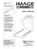 Image 14.6q User manual
-
NordicTrack T14vt Treadmill User manual
-
Epic EPTL09106.0 User manual
-
-
-
ProForm PFTL93105.0 User manual
-
-
 ADS Technologies PTV-305 Supplementary Manual


