
Frymaster, a member of the Commercial Food Equipment Service Association, recommends
using CFESA Certified Technicians.
24-Hour Service Hotline 1-800-551-8633
AUGUST 2006
www.frymaster.com Email: [email protected]
*8196202*
RE SERIES MARINE E
4
ELECTRIC FRYERS
Installation, Operation, Service and Parts Manual

NOTICE
IF, DURING THE WARRANTY PERIOD, THE CUSTOMER USES A PART FOR THIS ENODIS
EQUIPMENT OTHER THAN AN UNMODIFIED NEW OR RECYCLED PART PURCHASED
DIRECTLY FROM FRYMASTER DEAN, OR ANY OF ITS AUTHORIZED SERVICE CENTERS,
AND/OR THE PART BEING USED IS MODIFIED FROM ITS ORIGINAL CONFIGURATION, THIS
WARRANTY WILL BE VOID. FURTHER, FRYMASTER DEAN AND ITS AFFILIATES WILL NOT BE
LIABLE FOR ANY CLAIMS, DAMAGES OR EXPENSES INCURRED BY THE CUSTOMER WHICH
ARISE DIRECTLY OR INDIRECTLY, IN WHOLE OR IN PART, DUE TO THE INSTALLATION OF
ANY MODIFIED PART AND/OR PART RECEIVED FROM AN UNAUTHORIZED SERVICE CENTER.
DANGER
Copper wire suitable for at least 167°F (75°C) must be used for power connections.
DANGER
The electrical power supply for this appliance must be the same as indicated on the rating and
serial number plate located on the inside of the fryer door.
DANGER
This appliance must be connected to the voltage and phase as specified on the rating and serial
number plate located on the inside of the fryer door.
DANGER
All wiring connections for this appliance must be made in accordance with the wiring diagrams
furnished with the equipment. Wiring diagrams are located on the inside of the fryer door.
DANGER
Do not store or use gasoline or other flammable vapors and liquids in the vicinity of this or any
other appliance.
NOTICE
Drawings and photos used in this manual are intended to illustrate operational, cleaning and
technical procedures. They may differ slightly in appearance or placement between fryers but
functionality should remain the same. They may not conform to onsite management operational
procedures.
WARNING
Frymaster fryers equipped with legs are for permanent installations. Fryers fitted with legs
must be lifted during movement to avoid damage and possible bodily injury. For a moveable or
portable installation, Frymaster optional equipment casters must be used.
Questions? Call 1-800-551-8633 or email: [email protected]
DANGER
The front ledge of the fryer is not a step. Do not stand on the fryer. Serious injury can result
from slips or contact with the hot oil.
WARNING
This equipment is intended for indoor use only. Do not install or operate this equipment in
outdoor areas.

NOTICE
This appliance is intended for professional use only and is to be operated by qualified
personnel only. A Frymaster DEAN Factory Authorized Service Center (FASC) or other qualified
professional should perform installation, maintenance, and repairs. Installation, maintenance,
or repairs by unqualified personnel may void the manufacturer’s warranty.
NOTICE
This equipment must be installed in accordance with the appropriate national and local codes of
the country and/or region in which the appliance is installed.
NOTICE TO U.S. CUSTOMERS
This equipment is to be installed in compliance with the basic plumbing code of the Building
Officials and Code Administrators International, Inc. (BOCA) and the Food Service Sanitation
Manual of the U.S. Food and Drug Administration.
WARNING
No structural material on the fryer should be altered or removed to accommodate placement of
the fryer under a hood. Questions? Call the Frymaster Dean Service Hotline at 1-800-551-8633.
NOTICE TO OWNERS OF UNITS EQUIPPED WITH COMPUTERS
U.S.
This device complies with Part 15 of the FCC rules. Operation is subject to the following two
conditions: 1) This device may not cause harmful interference, and 2) This device must accept
any interference received, including interference that may cause undesired operation. While
this device is a verified Class A device, it has been shown to meet the Class B limits.
CANADA
This digital apparatus does not exceed the Class A or B limits for radio noise emissions as set
out by the ICES-003 standard of the Canadian Department of Communications.
Cet appareil numerique n’emet pas de bruits radioelectriques depassany les limites de classe A
et B prescrites dans la norme NMB-003 edictee par le Ministre des Communcations du Canada.
DANGER
Improper installation, adjustment, maintenance or service, and unauthorized alterations or
modifications can cause property damage, injury, or death. Read the installation, operating,
and service instructions thoroughly before installing or servicing this equipment.
DANGER
The crumb tray in fryers equipped with a filter system must be emptied into a fireproof container
at the end of frying operations each day. Some food particles can spontaneously combust if left
soaking in certain shortening material.
WARNING
Do not bang fry baskets or other utensils on the fryer’s joiner strip. The strip is present to seal
the joint between the frypots. Banging fry baskets on the strip to dislodge shortening will
distort the strip, adversely affecting its fit. It is designed for a tight fit and should only be
removed for cleaning.
WARNING
Never spray the fryer with water or use water jets to clean the fryer.

i
RE Series Marine Electric Fryers
Installation, Operation, Service and Parts Manual
TABLE OF CONTENTS
CHAPTER 1: Introduction
1.1 General ..............................................................................................................................1-1
1.2 Safety Information.............................................................................................................1-1
1.3 Controller Information ......................................................................................................1-2
1.4 Shipping Damage Claim Procedure..................................................................................1-2
1.5 Service Information...........................................................................................................1-2
CHAPTER 2: Installation Instructions
2.1 Introduction.......................................................................................................................2-1
2.2 Power Requirements..........................................................................................................2-2
2.3 Installation.........................................................................................................................2-3
2.4 After the Fryers are Anchored at the Frying Station.........................................................2-3
2.5 Dimensions and Weights...................................................................................................2-4
CHAPTER 3: Operating Instructions
3.1 Equipment Setup and Shutdown Procedures.....................................................................3-1
3.2 Operation of the Solid-State Digital Controller ................................................................3-2
CHAPTER 4: Filtration Instructions
4.1 Introduction.......................................................................................................................4-1
4.2 Preparing the Filter for Use...............................................................................................4-1
4.3 Operation of the Filter.......................................................................................................4-3
4.4 Draining and Disposing of Waste Oil ...............................................................................4-5
CHAPTER 5: Preventive Maintenance
5.1 Cleaning the Fryer.............................................................................................................5-1
5.1.1 Clean Inside and Outside of the Fryer Cabinet ..................................................5-1
5.1.2 Clean the Built in Filtration System...................................................................5-1
5.1.3 Clean the Frypot and Heating Elements (Boil-Out)...........................................5-2
5.1.4 Clean Detachable Parts and Accessories............................................................5-3
5.2 Annual/Periodic System Inspection ..................................................................................5-3

ii
CHAPTER 6: Operator Troubleshooting
6.1 Introduction.......................................................................................................................6-1
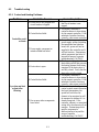
6.2 Troubleshooting.................................................................................................................6-2
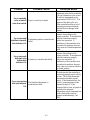
6.2.1 Control and Heating Problems...........................................................................6-2
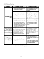
6.2.2 Filtration Problems.............................................................................................6-4
CHAPTER 7: Service Procedures
7.1 General ..............................................................................................................................7-1
7.2 Replacing a Remote Digital Controller.............................................................................7-1
7.3 Replacing Component Box Components.......................................................................... 7-1
7.4 Replacing a High-Limit Thermostat..................................................................................7-2
7.5 Replacing a Temperature Probe........................................................................................7-3
7.6 Replacing a Heating Element............................................................................................7-4
7.7 Replacing Contactor Box Components.............................................................................7-6
7.8 Replacing a Frypot ............................................................................................................7-7
7.9 Built in Filtration System Service Procedures ..................................................................7-9
7.9.1 Filtration System Problem Resolution ...............................................................7-9
7.9.2 Replacing the Filter Motor, Filter Pump and Related Components.................7-10
7.9.3 Replacing the Filter Transformer or Filter Relay.............................................7-11
7.10 Interface Board Diagnostic Chart....................................................................................7-12
7.11 Probe Resistance Chart....................................................................................................7-13
7.12 Wiring Diagram, Simplified RE17..................................................................................7-14
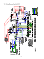
7.13 Wiring Diagram, System.................................................................................................7-15
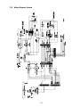
7.14 Wiring Diagram, Contactor Box.....................................................................................7-16
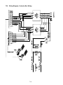
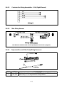
7.15 Wiring Diagram, Wiring Harnesses................................................................................7-17
7.16 Wiring Diagram, Remote Cable......................................................................................7-18
CHAPTER 8: Parts List
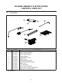
8.1 Accessories........................................................................................................................8-1
8.2 Cabinetry...........................................................................................................................8-2
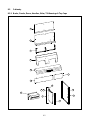
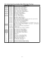
8.2.1 Backs, Panels, Doors, Handles, Sides, Tilt Housings & Topcaps......................8-2
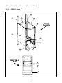
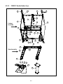
8.2.2 Cabinet Bases, Braces and Associated Parts......................................................8-4
8.2.2.1 FPRE117 Single ...................................................................................8-4
8.2.2.2 FPRE217 Double..................................................................................8-6
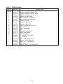
8.3 Drain System Components................................................................................................8-8
8.3.1 FPRE217 Euro-Look Drain Tube Sections and Parts........................................8-8
8.3.2 Drain Valve Assembly and Component Parts....................................................8-9
8.3.2.1 FPRE117 Single Drain Valve Assembly.............................................8-9
8.3.2.2 FPRE217 Euro-Look Drain Valve Assembly...................................8-10
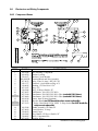
8.4 Electronics and Wiring Components...............................................................................8-11
8.4.1 Component Boxes ............................................................................................8-11
8.4.2 Contactor Boxes...............................................................................................8-12
8.4.3 Terminal Blocks...............................................................................................8-14
8.4.4 Heating Element Assembly and Associated Parts............................................ 8-15
8.4.5 Remote Digital Controller................................................................................8-17

iii
8.4.6 Wiring Assemblies and Harnesses...................................................................8-17
8.4.6.1 Contactor Box Wiring Assembly 12-Pin...........................................8-17
8.4.6.2 Contactor Box Wiring Assembly 6-Pin Left Element.......................8-17
8.4.6.3 Contactor Box Wiring Assembly 9-Pin Right Element ....................8-18
8.4.6.4 Main Wiring Harness ........................................................................8-18
8.4.6.5 Component Box Wiring Harness ......................................................8-18
8.5 Filtration System Components........................................................................................ 8-19
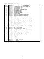
8.5.1 FPRE117 Single Filtration Components..........................................................8-19
8.5.2 FPRE217 Filtration Components .....................................................................8-21
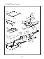
8.6 Frypot Assembly and Thermostat ...................................................................................8-23
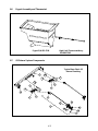
8.7 FPRE217 Oil Return System Components .....................................................................8-23
8.8 Oil Disposal Plumbing ....................................................................................................8-25
8.9 Wiring Connectors, Pin Terminals, Seals and Power Cords........................................... 8-26
8.10 Fasteners..........................................................................................................................8-28

1-1
RE SERIES MARINE E
4
ELECTRIC FRYERS
CHAPTER 1: INTRODUCTION
1.1 General
Read the instructions in this manual thoroughly before attempting to operate this equipment. This
manual covers all configurations of RE Series Electric Fryer models specifically configured for use
aboard surface ships, including FPRE117 kW and FPRE217F kW models. The fryers in this model
family have most parts in common, and when discussed as a group, will be referred to as “RE Series
Marine Electric” fryers.
The RE Series Marine Electric fryers feature a built-in filtration system and also include features
such as deep cold-zones and open frypots with rotating elements. These fryers are equipped with
remote mounted solid-state digital controllers. Fryers in this series can be single units or grouped in
batteries of two or more fryers.
1.2 Safety Information
Before attempting to operate your unit, read the instructions in this manual thoroughly.
Throughout this manual, you will find notations enclosed in double-bordered boxes similar to the
one below.
DANGER
Hot cooking oil causes severe burns. Never attempt to move a fryer containing hot
oil or to transfer hot oil from one container to another.
CAUTION boxes contain information about actions or conditions that may cause or result in a
malfunction of your system.
WARNING boxes contain information about actions or conditions that may cause or result in
damage to your system, and which may cause your system to malfunction.
DANGER boxes contain information about actions or conditions that may cause or result in
injury to personnel, and which may cause damage to your system and/or cause your system to
malfunction.
Fryers in this series are equipped with the following automatic safety features:
1. Two high-temperature detection features one of which sounds an alarm and the other shuts off
power to the elements should the temperature control fail and the temperature continue to rise.
2. A safety switch built into the drain valve, which prevents the elements from heating with the
drain valve even partially open.
3. A magnetic tilt switch that shuts off the elements when lifted for frypot cleaning.

1-2
1.3 Controller Information
This equipment has been tested and found to comply with the limits for a Class A digital device,
pursuant to Part 15 of the FCC rules. While this device is a verified Class A device, it has been
shown to meet the Class B limits. These limits are designed to provide reasonable protection against
harmful interference when the equipment is operated in a commercial environment. This equipment
generates, uses and can radiate radio frequency energy and, if not installed and used in accordance
with the instruction manual, may cause harmful interference to radio communications.
The user may find the following booklet prepared by the Federal Communications Commission
helpful: "How to Identify and Resolve Radio-TV Interference Problems". This booklet is available
from the U.S. Government Printing Office, Washington, DC 20402, Stock No. 004-000-00345-4.
1.4 Shipping Damage Claim Procedure
What to do if this equipment arrives damaged:
Please note that this equipment was carefully inspected and packed by skilled personnel before
leaving the factory. The freight company assumes full responsibility for safe delivery upon
acceptance of the equipment.
1. File Claim for Damages Immediately—Regardless of extent of damage.
2. Visible Loss or Damage—Be sure this is noted on the freight bill or express receipt and is signed
by the person making the delivery.
3. Concealed Loss or Damage—If damage is unnoticed until equipment is unpacked, notify the
freight company or carrier immediately and file a concealed damage claim. This should be done
within 15 days of date of delivery. Be sure to retain container for inspection.
1.5 Service Information
For non-routine maintenance or repairs, or for service information, contact your local Frymaster
Authorized Service Center (FASC). Service information may also be obtained by calling the
Frymaster Technical Services Department at 1-800-551-8633 or via e-mail at
[email protected]. The following information will be needed in order to assist you efficiently:
Model Number:
Serial Number:
Voltage:
Also be prepared to describe the specific problem.
RETAIN AND STORE THIS MANUAL IN A SAFE PLACE FOR FUTURE USE.

2-1
RE SERIES MARINE E
4
ELECTRIC FRYERS
CHAPTER 2: INSTALLATION INSTRUCTIONS
2.1 Introduction
The instructions in this chapter cover all configurations of RE Series Marine Electric Fryer models
specifically configured for use aboard surface ships, including FPRE117 kW and FPRE217 kW
models. The instructions do not cover and may not be used for installations ashore.
Proper installation is essential for the safe, efficient, trouble-free operation of this appliance.
Any unauthorized alteration of this equipment will void the Frymaster warranty.
NOTICE
All fryers shipped without factory supplied cords and plug assemblies must be
hardwired using flexible conduit to the terminal block located on the rear of the fryer.
These fryers should be wired to NEC specifications. Hardwired units must include
installation of restraint devices.
DANGER
Adequate means must be provided to limit the movement of this appliance without
depending on or transmitting stress to the electrical conduit.
NOTICE
If this equipment is wired directly into the electrical power supply, a means for
disconnection from the supply having a contact separation of at least 3-mm in all
poles must be incorporated in the fixed wiring.
NOTICE
This equipment must be positioned so that the plug is accessible unless other
means for disconnection from the power supply (e.g., a circuit breaker) is provided.
NOTICE
If this appliance is permanently connected to fixed wiring, it must be connected by
means of copper wires having a temperature rating of not less than 167°F (75°C).
NOTICE
If the electrical power supply cord is damaged, it must be replaced by a Frymaster
Dean Factory Authorized Service Center technician or a similarly qualified person in
order to avoid a hazard.
DANGER
This appliance must be connected to a power supply having the same voltage and
phase as specified on the rating plate located on the inside of the appliance door.

2-2
DANGER
All wiring connections for this appliance must be made in accordance with the
wiring diagram(s) furnished with the appliance. Refer to the wiring diagram(s)
affixed to the inside of the appliance door when installing or servicing this
equipment.
DANGER
The appliance area must be kept free and clear of combustible material at all times.
WARNING
Do not block the area around the base or under the fryers.
All installation and service on FRYMASTER equipment must be performed by qualified, certified,
licensed, and/or authorized installation or service personnel.
Service may be obtained by contacting a local Frymaster DEAN Factory Authorized Service Center.
In the event of a power failure, the fryer(s) will automatically shut down. If this occurs, turn the
power switch OFF. Do not attempt to start the fryer(s) until power is restored.
A clearance of 6 inches (15cm) must be provided at both sides and back adjacent to combustible
construction. A minimum of 24 inches (61cm) should be provided at the front of the equipment for
servicing and proper operation.
Connections should be made by means of an approved, flexible-metallic or rubber-covered electrical
cable and quick-disconnect plug. The fryers may be installed with “hard-wired” connections, but
use of quick-disconnect plugs will facilitate service if required. Connections are made to the fryer
power input terminal block located in the lower back of the fryer(s).
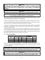
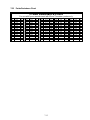
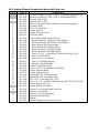
2.2 Power Requirements
Use copper wire ONLY, suitable for at least 167°F (75°C)
MODEL VOLTAGE PHASE
WIRE
SERVICE
MINIMUM WIRE
SIZE
AWG mm
AMPS
(per leg)
FPRE117 440 3 3 6 (4.11) 23
FPRE117 480 3 3 6 (4.11) 21
FPRE217(Per Vat) 440 3 3 6 (4.11) 23
FPRE217 (Per Vat) 480 3 3 6 (4.11) 21
RE Series Marine electric fryers are equipped with a filter system that requires a separate 120VAC
or 220VAC depending on configuration, single-phase, 3-wire, 20 amp service (refer to wiring
diagram on page 7-15).
NOTICE
If this appliance is permanently connected to fixed wiring, it must be connected by
means of copper wires having a temperature rating of not less than 167°F (75°C).
DANGER
This appliance must be connected to a power supply having the same voltage and
phase as specified on the rating plate located on the inside of the appliance door.

2-3
DANGER
All wiring connections for this appliance must be made in accordance with the
wiring diagram(s) furnished with the appliance. Refer to the wiring diagram(s)
affixed to the inside of the appliance door when installing or servicing this
equipment.
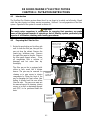
2.3 Installation
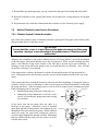
Shipboard installations are often unique, however, here’s a list of do’s and don’ts to avoid trouble:
Do ensure the fryer is adequately attached to the deck.
Do ensure the fryer is mounted well away from appliances, which are
sprayed with water.
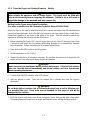
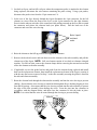
Do mount the remote controller within easy reach of the operator and away
from the heat and vapors of the fryer vat and other cooking equipment.
Do remove the 15-pin plug from the controller cable with a pin pusher
before routing it to the fryer and carefully reattach, using the provided
diagram in section 7.15.
Don’t mount the remote controller on the fryer’s flue cap or on the
bulkhead above the fryer vat.
Don’t cut and splice the remote controller’s cable to facilitate routing it to
the fryer.
2.4 After Fryers Are Anchored At the Frying Station
1. Close frypot drain-valve(s) and fill frypot(s) with water to the bottom oil level line.
2. Boil out frypot(s) in accordance with the instructions in Section 5.1.3 of this manual.
3. Drain, clean, and fill frypot(s) with cooking oil. (See Equipment Setup and Shutdown
Procedures in Chapter 3.)
DO NOT mount the
controller on the fryer’s
flue cap or on the
bulkhead above the
fryer’s vat.
DO use a pin pusher
to remove the 15-pin
plug on the controller
cable for routing.
DANGER
No structural material on the fryer should be altered or
removed to accommodate placement of the fryer under a
hood. Questions? Call the Frymaster Dean Service
Department at 1-800-551-8633 or via e-mail at
DANGER
Hot oil can cause severe burns. Avoid contact. Under all circumstances, oil must
be removed from the fryer before attempting to move it to avoid oil spills, falls and
severe burns. This fryer may tip and cause personal injury if not secured in a
stationary position.

2-4
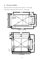
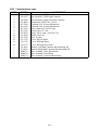
2.5 Dimensions and Weights
Single Fryer (with filter): LWH (inches) 28.33 X 15.58 X 45.5 – 295 lbs. empty.
2-Fryer Battery: LWH (inches) 28.30 X 31.45 X 45.5 – 490 lbs. empty.
Single Fryer (with filter)
Mounting
Holes
Ø.625
4 Places
28.30
2.470
Typical
26.315
7.098
Typical
31.62
31.62
31.45
17.515
Back of Fryer Unit
2-Fryer Battery

3–1
RE SERIES MARINE E
4
ELECTRIC FRYERS
CHAPTER 3: OPERATING INSTRUCTIONS
3.1 Equipment Setup and Shutdown Procedures
Setup
DANGER
Never operate the appliance with an empty frypot. The frypot must be filled with
water, oil or shortening before energizing the elements. Failure to do so will result in
irreparable damage to the elements and may cause a fire.
DANGER
Remove all drops of water from the frypot before filling with oil or shortening.
Failure to do so will cause spattering of hot liquid when the oil or shortening is
heated to cooking temperature.
1. Fill the frypot with oil to the bottom OIL LEVEL line located on the rear of the frypot. This will
allow for oil expansion as heat is applied. Do not fill cold oil any higher than the bottom line;
overflow may occur as heat expands the oil.
NOTE: If solid shortening is used, first raise the elements, then pack the shortening into the
bottom of the frypot. Lower the elements, and then pack the shortening around and over the
elements to the lower mark. It may be necessary to add shortening to bring the level up to the
upper mark after the packed shortening has melted. Cooking oil/shortening capacity of H17
series fryer is 50 lbs. (25 liters) at 70°F (21°C).
DANGER
Never set a complete block of solid shortening on top of the heating elements.
When using solid shortening, always pre-melt the shortening before adding it to the
frypot. If the shortening is not pre-melted, it must be packed down into the bottom of
the frypot and between the elements, and the fryer must be started in the melt-cycle
mode.
Never cancel the melt-cycle mode when using solid shortening. Doing so will result
in damage to the elements and increase the potential for a flash fire.
2. Replace the basket support rack on top of the heating elements.
3. If the fryer is not hard-wired into the power supply, ensure that the power cord is plugged into
the appropriate receptacle. Verify that the face of the plug is flush with the outlet plate, with no
portion of the prongs visible.

3–2
4. Ensure that the oil level is at the top OIL LEVEL line when the oil is at its cooking temperature.
It may be necessary to add oil to bring the level up to the upper mark, after it has reached
cooking temperature.
Shutdown
1. Turn the fryer off.
2. Filter the oil and clean the fryers (See Chapters 4 and 5).
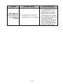
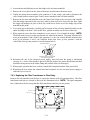
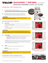
3.2 Operation of the Solid-State Digital Controller (operation of other controllers is
covered in the Frymaster Controllers Manual PN 819-5616)
NOTE: Refer to Chapter 4 of this manual for operating instructions for the built-in filtration system.
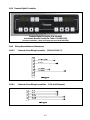
Fryers configured for marine use are equipped with remotely mounted solid-state digital controllers.
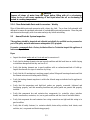
Marine Solid-State Digital Controller
ITEM DESCRIPTION
1 Lighted Display – LED display for a full-pot fryer. Displays setpoint temperature.
2 On/Off Switch – Switches the power On or Off.
3 C/F Switch – Toggles the display between Fahrenheit and Celsius
4
Lighted Display- LED Display – Displays current frypot temperature and heat mode light (decimal)
will alternately illuminate as the elements cycle on and off.
5
Temperature / Setpoint Display Switch –Toggles the display between frypot temperature and
setpoint temperature.
6 Up Arrow – Raises setpoint temperature.
7 Down Arrow – Lowers the setpoint temperature.
8 Melt-Cycle Cancel Switch – Cancels the melt-cycle mode.
The digital controller, illustrated above, is used to maintain oil at the temperature indicated by the
controller.
1 2
5 6 7 8
3 4

3–3
The fryer has two built-in high-limit protection features. If the temperature in the frypot reaches
411°F (210°C), an alarm will sound. In the event that the temperature continues to rise, there is a
second and separate high limit circuit that will shut down the system at 425° (218°C), sound an
alarm and display “help”.
A shunt trip device is integrated into the marine specifications. The shunt trip is a contact, which is
closed by a coil in the fryer’s 24-volt safety circuit. Leads from the shunt trip extend from the fryer
and can be wired to a specialized shipboard circuit breaker. Voltage from the ship passes through the
closed shunt trip on the fryer, keeping the ship’s circuit breaker closed. If the fryer’s safety circuit
opens due to the high-limit opening or the opening of a drain valve while the fryer is on, the shunt-
trip circuit on the fryer opens, which opens the ship’s circuit breaker, killing power to the fryer.
The digital controller has no timing features, so the operator must monitor cooking.
WARNING
Before pressing the power switch to the ON position, ensure that the frypot is
properly filled with oil. See Section 3.1.
CONTROLLER OPERATING PROCEDURE
1. Turn the power switch ON.
2. Verify that the control is set to the desired cooking temperature.
3. Press the power switch to the ON position. The POWER light will illuminate.
4. If the frypot temperature is below 180°F (82°C), the controller will automatically enter a warm-
up cycle (often called a melt cycle). The heating elements will cycle on and off repeatedly,
allowing the oil to heat gradually, without scorching. During the warm-up cycle, the heating
mode light (decimal point) will alternately illuminate and go off as the elements cycle on and off.
When the frypot temperature reaches 180°F (82°C), the controller will exit the warm-up cycle
and the heating mode light will remain continuously illuminated.
5. When the oil temperature reaches the setpoint, the elements will cycle OFF and the HEAT light
will go off, indicating that the fryer is ready for the cooking process to begin.
INTRODUCTION
The Digital Controller allows the operator to program the frypot setpoint and to toggle the display
between the frypot temperature and the programmed setpoint. The setpoint is an operator-
determined frying temperature. When the controller is turned on, it automatically brings the cooking
oil to the setpoint and maintains it at that temperature until the controller is turned off. Units display
the setpoint by default. This controller also features a programmable melt-cycle cancel switch and a
switch for toggling the temperature display between Fahrenheit and Celsius as well as toggling
between the setpoint and the actual temperature.

3–4
The controller has three error display messages:
, indicating a heating problem or drain valve problem. Turn the fryer off reset the drain
handle and try again. If the error still appears, call the Frymaster hotline.
and actual frypot temperature, indicating that the shortening temperature is above 411°F
(210°C). If this display is seen, turn the fryer off immediately and contact an authorized service
center.
, indicating that the controller has detected a problem in the temperature measuring circuits
and control circuits. Turn the fryer off and contact an authorized service center.
NOTE: This controller is configured for the fryer on which it installed (i.e., gas or electric and full-
or split-pot). Although identical in appearance, controllers configured for use on one type of fryer
are not interchangeable with those configured for use on another type.
CONTROLLER OPERATING INSTRUCTIONS
1. Turn the controller on by pressing the ON/OFF switch .
The controller software version number will display for four seconds then, in non-CE units, the
setpoint temperature will appear in the display. In CE units, the frypot temperature will appear
in the display – to view the setpoint temperature, press the temperature switch for the frypot
in question.
A decimal point will appear between the first two numbers of the display, indicating that the unit
is heating. When the frypot has reached the setpoint temperature, the heat indicator decimal
point will go out, indicating that the fryer is ready for cooking.
2. Adjust the setpoint if necessary. To raise the setpoint temperature, press an up arrow . Press
a down arrow to lower the setpoint temperature.
The display will change at the rate of approximately one-degree per second initially. If the arrow
is pressed and held, after a change of about 12°, the rate of change will increase, allowing large
changes in setpoint temperature to be made quickly.
SELECTING FAHRENHEIT OR CELSIUS DISPLAY MODE
To toggle the temperature display between Fahrenheit and Celsius, press the right C/F switch .
The display(s) will change from xxx°F to xxx°C, where “xxx” is the frypot or setpoint temperature
.
CANCELING THE MELT-CYLE
DANGER
Do not cancel the melt-cycle mode if using solid shortening!
The melt-cycle is designed to prevent scorching shortening and overheating the frypot or elements
while gradually melting blocks of shortening. The controller automatically starts the fryer in the

3–5
melt-cycle mode and remains in this mode until the frypot temperature reaches 180°F (82°C) or the
melt-cycle is cancelled by the operator. If you are not using solid shortening, you may cancel the
melt-cycle.
To cancel the melt-cycle on a full-pot unit, press the right melt-cycle cancel switch . On a split-
pot unit, press the left switch for the left frypot or the right switch for the right frypot.
DISABLING OR ENABLING THE MELT-CYCLE CANCEL SWITCH
The controller can be programmed to disable the melt-cycle cancel switch to prevent accidentally
canceling the melt-cycle.
1. With the controller in the OFF mode, press the melt-cycle cancel switch . The display will
show either "0", meaning that the melt-cycle can be bypassed or a "1" meaning that the melt-
cycle cannot be bypassed.
2. To change the bypass configuration, press and hold the melt-cycle cancel switch for five to six
seconds to toggle the "0" to "1" or "1" to "0". Release the switch when the display shows the
desired setting.

4-1
RE SERIES MARINE E
4
ELECTRIC FRYERS
CHAPTER 4: FILTRATION INSTRUCTIONS
4.1 Introduction
The FootPrint Pro filtration system allows the oil in one frypot to be safely and efficiently filtered
while the other frypots in a battery remain in operation. Section 4.2 covers preparation of the filter
system. Operation of the system is covered in section 4.3.
WARNING
The work center supervisor is responsible for ensuring that operators are made
aware of the inherent hazards of operating a hot oil filtering system, particularly the
aspects of oil filtration, draining and cleaning procedures.
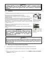
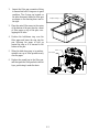
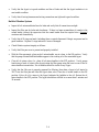
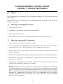
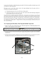
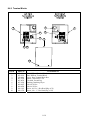
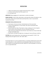
4.2 Preparing the Filter for Use
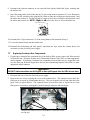
1. Rotate the pan-locking rod to either side
until it clears the filter pan, then pull the
pan out from the cabinet. Remove the
crumb tray, hold-down ring. Remove
the used filter paper in the pan. Remove
the filter paper support screen. Clean
all components with a solution of
detergent and hot water then dry
thoroughly.
The filter pan on the is equipped with
rollers in rails, much like a kitchen
drawer. The pan may be removed for
cleaning or to gain access to interior
components by lifting the front of the
pan to disengage the front rollers, then
pulling it forward until the rear rollers
clear the rails. The pan cover must not
be removed except for cleaning, interior
access, or to allow a shortening disposal
unit (SDU) to be positioned under the
drain.
Rotate the locking rod
to either side to allow
the pan to be pulled
out from the fryer.
FPRE217
Screen and
Filter Pan
FPRE117
Screen and
Filter Pan

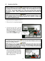
4-2
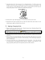
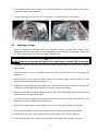
Inspect O-Rings
Screen
Filter Paper
2. Inspect the filter pan connection fitting
to ensure that both O-rings are in good
condition. The O-rings are located on
the tube disconnect inside the filter pan
as shown on the drawing down and to
the right.
3. Place the metal filter screen in the cente
r
of the bottom of the pan, then lay a sheet
of filter paper on top of the pan, over-
lapping on all sides.
4. Position the hold-down ring over the
filter paper and lower the ring into the
pan, allowing the paper to fold up
around the ring as it is lowered to the
bottom of the pan.
5. When the hold-down ring is in position,
sprinkle one cup of filter powder evenly
over the paper.
6. Replace the crumb tray in the filter pan,
and then push the filter pan back into the
fryer, positioning it under the drain.

4-3
4.3 Operation of the Filter
DANGER
Draining and filtering of oil must be accomplished with care to avoid the possibility
of a serious burn caused by careless handling. The oil to be filtered is at or near
350°F (177°C). Ensure drain handles are in their proper position before operating
any switches or valves. Wear all appropriate safety equipment when draining and
filtering oil.
DANGER
NEVER attempt to drain oil from the fryer with the elements energized! Doing so will
cause irreparable damage to the elements and may cause a flash fire. Doing so will
also void the Frymaster warranty.
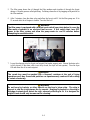
1. Ensure that the filter is prepared. See Sec. 4.2
2. Make sure the oil is at operating temperature.
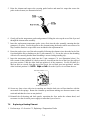
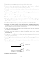
3. Turn the fryer power OFF. Drain the
frypot into the filter pan. Remove the
basket support rack and raise the element
assembly to the up position. If necessary,
use the Fryer's Friend clean-out rod to
clear the drain from inside the frypot.
DANGER
Do not drain more than one frypot at a time into the built-in filtration unit to avoid
overflow and spillage of hot oil.
DANGER
NEVER attempt to clear a clogged drain valve from the front of the valve! Hot oil will
rush out creating the potential for severe burns. DO NOT hammer on the drain valve
with the cleanout rod or other objects. Damage to the ball inside will result in leaks
and will void the Frymaster warranty.
4. After the oil has drained from the frypot,
turn the filter handle to the ON position
to start the pump and begin the filtering
process. Make sure the drain valve is left
open. There may be a slight delay
before the pump activates.
Open valve by
rotating the handle
90º.
Turn filter handle
to the ON
p
osition.
Page is loading ...
Page is loading ...
Page is loading ...
Page is loading ...
Page is loading ...
Page is loading ...
Page is loading ...
Page is loading ...
Page is loading ...
Page is loading ...
Page is loading ...
Page is loading ...
Page is loading ...
Page is loading ...
Page is loading ...
Page is loading ...
Page is loading ...
Page is loading ...
Page is loading ...
Page is loading ...
Page is loading ...
Page is loading ...
Page is loading ...
Page is loading ...
Page is loading ...
Page is loading ...
Page is loading ...
Page is loading ...
Page is loading ...
Page is loading ...
Page is loading ...
Page is loading ...
Page is loading ...
Page is loading ...
Page is loading ...
Page is loading ...
Page is loading ...
Page is loading ...
Page is loading ...
Page is loading ...
Page is loading ...
Page is loading ...
Page is loading ...
Page is loading ...
Page is loading ...
Page is loading ...
Page is loading ...
Page is loading ...
Page is loading ...
Page is loading ...
Page is loading ...
Page is loading ...
Page is loading ...
Page is loading ...
Page is loading ...
Page is loading ...
Page is loading ...
Page is loading ...
-
 1
1
-
 2
2
-
 3
3
-
 4
4
-
 5
5
-
 6
6
-
 7
7
-
 8
8
-
 9
9
-
 10
10
-
 11
11
-
 12
12
-
 13
13
-
 14
14
-
 15
15
-
 16
16
-
 17
17
-
 18
18
-
 19
19
-
 20
20
-
 21
21
-
 22
22
-
 23
23
-
 24
24
-
 25
25
-
 26
26
-
 27
27
-
 28
28
-
 29
29
-
 30
30
-
 31
31
-
 32
32
-
 33
33
-
 34
34
-
 35
35
-
 36
36
-
 37
37
-
 38
38
-
 39
39
-
 40
40
-
 41
41
-
 42
42
-
 43
43
-
 44
44
-
 45
45
-
 46
46
-
 47
47
-
 48
48
-
 49
49
-
 50
50
-
 51
51
-
 52
52
-
 53
53
-
 54
54
-
 55
55
-
 56
56
-
 57
57
-
 58
58
-
 59
59
-
 60
60
-
 61
61
-
 62
62
-
 63
63
-
 64
64
-
 65
65
-
 66
66
-
 67
67
-
 68
68
-
 69
69
-
 70
70
-
 71
71
-
 72
72
-
 73
73
-
 74
74
-
 75
75
-
 76
76
-
 77
77
-
 78
78


Ask a question and I''ll find the answer in the document
Finding information in a document is now easier with AI
Related papers
-
 Frymaster 8196428 User manual
-
 Frymaster BIPH14 User manual
-
 Frymaster YFPRE1817E User manual
-
 Frymaster 2836 User manual
-
 Frymaster 2836 Specification
-
 Frymaster RE14 User manual
-
 Frymaster e4 User manual
-
 Frymaster MPF50S Series User manual
-
 Frymaster Fryer Controllers User manual
-
 Frymaster 2836 Series Electric Fryers User manual


Other documents
-
Keating 14CM User manual
-
Keating TS User manual
-
 VULCAN & WOLF QuickFry Start Up User guide
-
-
 KAT'S 4270099 Owner's manual
-
Imperial IFS-40-E-LOE (CE366) Owner's manual
-
JONARD TOOLS MF-5-25 Operating instructions
-
Bennett Marine ES2000 User manual
-
Pitco Frialator ME14S-C/MFD User manual
-
 Sportsman Series CORDP3025 User manual


