Page is loading ...

6GB SERIES
MODELS 711F & 721F
IRON GLOBE VALVE
INSTALLATION
OPERATION
MAINTENANCE
GUIDE
DOCUMENT NO.: ES-1494
REVISION LEVEL: A
ISSUED BY: Bill Hooks DATE: 09/25/13
APPROVED BY: _________________ DATE: _______

APOLLO
®
IRON GLOBE VALVE IOM GUIDE Page 2 of 7
ES1494 IOM Iron Globe Valve 1418 S. Pearl Street Pageland SC USA 29728
I
NTRODUCTION
......................................................................... 3
Table 1. Apollo Series & Model Numbers ................................................................... 3
Table 2. Apollo Pipe Size (x) Designations .................................................................. 3
Table 3. Apollo Globe Valve Material Designation ...................................................... 4
Pressure/Temperature Ratings ................................................................................. 4
Product Marking ...................................................................................................... 5
Figure 1. APOLLO
Gate Valve Nameplate……………………………………………………….5
I
NSTALLATION
........................................................................... 5
Installation Instructions ........................................................................................... 5
Table 4. Iron Flange – Class 125 stud sizes ............................................................... 6
Table 5. Iron Flange – Class 250 stud sizes ............................................................... 6
Figure 2. Bolt Tightening Sequence ........................................................................... 6
O
PERATION
............................................................................... 7
M
AINTENANCE
.......................................................................... 7
Table 6. Pressure - Temperature Ratings................................................................... 7
Table 7. Bonnet Bolt Torque ..................................................................................... 7
A
MENDMENT REGISTER
............................................................. 8

APOLLO
®
IRON GLOBE VALVE IOM GUIDE Page 3 of 7
ES1494 IOM Iron Globe Valve 1418 S. Pearl Street Pageland SC USA 29728
6GB-10x-01
Size Code
INTRODUCTION
The APOLLO
Iron Globe Valves covered in these guidelines are bolted bonnet and
outside screw and yoke – rising stem valve types. They are used to start, stop or throttle
the flow of fluid in a piping system. The valve is operated from a handwheel. Flow
through the valve is stopped by forcing a disc down onto the disc seal ring. Throttling of
flow is accomplished by turning handwheel to some location between fully open or fully
closed.
In OS&Y rising stem valves, the stem is held on to disc by swivel nut. Disc is fastened
securely to the end of the stem in such a manner as to allow these parts to swivel freely.
The disc is raised and lowered in the waterway by rotating the handwheel. The
handwheel fits onto the hex end of the yoke bushing and is held on by the handwheel nut
which is threaded onto the top of the yoke bushing. The inside diameter of the yoke has
threads that mate to the upper stem threads. The yoke bushing is held in the top of the
bonnet by the bonnet cap against the rim on the bottom of the yoke bushing. As the yoke
bushing is rotated, the stem and wedge move up and down. The stuffing box is formed by
the circular space between the stem and bonnet and is filled with non-asbestos packing.
The packing is compressed in the stuffing box by the packing gland bushing and packing
gland follower, which are drawn down against the packing by two gland bolts and nuts.
Table 1. APOLLO
®
Series & Model Numbers
SERIES MODEL DESCRIPTION
6GB-10x 711F Class 125 Flanged OS&Y, Bronze Mount
6GB-20x 721F Class 250 Flanged OS&Y, Bronze Mount
x – indicates pipe size. (Reference Table 2 below)
Table 2. APOLLO
®
Pipe Size (x) Designations
Pipe
Size
Apollo
code
Pipe
Size
Apollo
code
Pipe
Size
Apollo
code
Pipe
Size
Apollo
code
2” 8 5” B 12” H
20” N
2-1/2” 9 6” C 14” J
24” P
3” 0 8” E 16” K
4” A 10” G 18” M
Example:

APOLLO
®
IRON GLOBE VALVE IOM GUIDE Page 4 of 7
ES1494 IOM Iron Globe Valve 1418 S. Pearl Street Pageland SC USA 29728
Table 3. APOLLO
®
Globe Valve Material Designation
PART MATERIAL
BODY CAST IRON (ASTM A126 CL B)
GUIDE SPINDLE BRASS (ASTM B16)
SEAT RING CAST BRONZE (ASTM B62)
DISC SEAL RING CAST BRONZE (ASTM B62)
DISC CAST IRON (ASTM A126 CL B)
SWIVEL NUT CAST BRASS (ASTM B584)
STEM BRASS (ASTM B16)
BOLTS CARBON STEEL (ASTM A307 B)
GLAND FOLLOWER BOLTS CARBON STEEL (ASTM A307 B)
BODY GASKET GRAPHITE
BONNET CAST IRON (ASTM A126 CL B)
PACKING GRAPHITE
PACKING GLAND CAST BRASS (ASTM B584)
GLAND FOLLOWER DUCTILE IRON (ASTM A536 65-45-12)
GLAND FOLLOWER NUT CARBON STEEL (ASTM A307 B)
YOKE BUSHING CAST BRONZE (ASTM B62)
SCREW CARBON STEEL (ASTM A307 B)
HANDWHEEL CAST IRON (ASTM A126 CL B)
IDENTIFICATION PLATE ALUMINUM
WASHER CARBON STEEL (ASTM A307 B)
HANDWHEEL NUT DUCTILE IRON (ASTM A536 65-45-12)
Pressure/Temperature Ratings
Class 125
Saturated Steam: 125 psi (8.6 Bar) to 353°F(178°C) (2”-12”)
100 psi (6.9 Bar) to 338°F(170°C) (14”-24”)
Cold Working Pressure: 200 psi (13.8 Bar) at 100°F (2”-12”)
150 psi (10.3 Bar) at 100°F (14”-24”)
CLASS 250
Saturated Steam: 250 psi (17.2 Bar) to 406°F(207°C)
Cold Working Pressure: 500 psi (34.5 Bar) at 100°F
Note: Also see Table 6 in Operation section

APOLLO
®
IRON GLOBE VALVE IOM GUIDE Page 5 of 7
ES1494 IOM Iron Globe Valve 1418 S. Pearl Street Pageland SC USA 29728
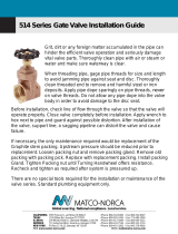
Product Marking
All APOLLO
Globe Valves are equipped with a nameplate attached under handwheel nut
(Figure 1). This plate provides the model number, part number, size, max pressure
rating, and date of manufacture.
FIGURE 1. APOLLO
IRON GLOBE VALVE NAMEPLATE
INSTALLATION
APOLLO
Globe Valves are designed for use between the faces of ANSI 125 and 250
pound flat flanges. Raised faced flanges are not recommended.
Globe valves are normally installed in horizontal pipe with vertical stem.
They can also be installed other than vertical, but this may require special construction
depending on valve size, service condition and medium. For a correct operation, Conbraco
recommends that the valve shall be oriented inclined above horizontal, with vertical being
the preferred orientation. Different positions may cause poor valve operation, and/or a
quick deterioration of the valve
Installation Instructions
Step 1. Check to make sure that the pipe flange and valve sealing faces are clean and
free from any debris (pipe scale, welding slag, etc.).
Step 2. Check the valve nameplate to ensure that the pressure and valve materials are
correct for the application.
WARNING! – APOLLO
Globe Valves should never be installed where service
conditions could exceed the valve ratings. Failure to heed warning may
result in personal injury or property damage.
Step 3. Place the valve between the two flanges of the pipe and put the seal gasket
between the valve flange and the pipe flange; make sure that it is correctly
positioned.
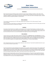
Step 4. Assemble the valve to the pipe using properly sized bolts for application. See
Tables 4 and 5 below. Progressively tighten to the torque value recommended by
the seal gasket provider. See Figure 2 for recommended method.
After the valve installation on the line and before the line pressurization, the following
activities must be performed:
- the packing bolts must be verified for tightness, DO NOT OVERTIGHTEN.
- the torque of the body-bonnet bolts must be verified for tightness
- the valve must be fully stroke operated

APOLLO
®
IRON GLOBE VALVE IOM GUIDE Page 6 of 7
ES1494 IOM Iron Globe Valve 1418 S. Pearl Street Pageland SC USA 29728
Table 4. Stud/Bolt Iron Flange – Class 125
Valve
Size Diameter
Length Qty
(in) (mm)
2 50 5/8” 3-1/2” 4
2.5 65 5/8” 3-3/4” 4
3 80 5/8” 3-3/4” 4
4 100 5/8” 3-3/4” 8
5 125 3/4” 4” 8
6 150 3/4” 4-1/4” 8
8 200 3/4” 4-1/2” 8
10 250 7/8” 4-3/4” 12
12 300 7/8” 5” 12
14 350 1” 5-1/2” 12
16 400 1” 5-1/2” 16
18 450 1-1/8” 16
20 500 1-1/8” 20
24 600 1-1/4” 20
Table 5. Stud/Bolt Iron Flange – Class 250
Valve
Size Diameter
Length Qty
(in) (mm)
2 50 5/8” 3-3/4” 8
2.5 65 5/8” 4-1/4” 8
3 80 5/8” 4-1/2” 8
4 100 5/8” 4-3/4” 8
5 125 5/8” 5” 8
6 150 5/8” 5” 12
8 200 7/8” 5-3/4” 12
10 250 1” 6-1/2” 16
12 300 1-1/8” 7” 16
14 350 1-1/8” 7-1/4” 20
16 400 1-1/4” 7-3/4” 20
18 450 1-1/4” 8” 24
20 500
24 600
1 5 1 5
1 3 12 9
8 3
8 3
4 2 4 7
4 7
6 2
10 11
6 2
1 19
1 13 16 5
15 5
12 9
8 9
8 13
12 3
18 3
4 11
4 17
10 7
14 7
6 16
14 2 10 11
6 15
20 2
FIGURE 2. Bolt Tightening Sequence

APOLLO
®
IRON GLOBE VALVE IOM GUIDE Page 7 of 7
ES1494 IOM Iron Globe Valve 1418 S. Pearl Street Pageland SC USA 29728
OPERATION
APOLLO
®
Globe valves are intended to provide years of reliable service for throttling
applications. Globe valves have high flow restriction and not recommended where
pressure drop is critical. Care should be taken when operating in either closed or open
position for extended periods of time. Line contamination may cause difficulty in opening
or closing. A routine cycling should be implemented depending on fluid condition and
usage.
Table 6. Pressure-temperature ratings
Temperature (°F)
Pressure (PSIG)
Class 125 Iron Class 250 Iron
Sizes Sizes Sizes Sizes
2-12 14-24 2-12 14-24
-20 to 100 200 150 500 300
150 200 150 500 300
200 190 135 460 280
250 175 125 415 260
300 165 110 375 240
350 150 100 335 220
400 140 290 200
450 125 250
MAINTENANCE
The APOLLO
®
Iron Globe Valves are designed for extended service with minimal wear and
servicing. Replacement parts are not available. The pipeline on either side of the valve
must be depressurized and drained prior to repair.
Valve Seat
Leakage through the valve is generally caused by foreign matter lodged in the seat seal.
This leakage can be overcome by cycling the valve or flushing. If leakage persists,
disassemble the valve and examine the seat surface on the disc and the seat ring. Minor
scratches can be corrected by polishing the sealing surfaces with 400 grit sandpaper.
Bonnet Joint
Leakage through the bonnet joint may be corrected by tightening bonnet bolts. Reference
Table 7 below for recommended torque values depending on bolt size. See Figure 2 for
recommended tightening sequence. If tightening does not correct leakage, replacement of
graphite gasket will be required.
Table 7. Bonnet Bolt Torque
Bolt size 5/8”
3/4”
7/8”
1” 1-1/8”
1-1/4”
1-3/8”
Torque (Ft. Lbs.)
90 150 200 300
475 660 885
Stem Packing
Leakage through the hand wheel stem may be corrected by tightening the packing nuts.
Excessive tightening may cause difficult operation of the valve. Tightness should be just
enough to stop the leak. If the packing gland screw has run out of travel, repacking
graphite gasket will be required.
Repacking of valves under pressure is NOT recommended. Even if valve is back seated foreign matter may
interfere with full closure and injury could occur.
/