Stairmaster HIITMill 9-4590 Owner's manual

Type
Owner's manual
Install
Page 1
620-8587 Rev. C
HIIT Console Wall Power Upgrade Install Instructions
Applies to: Airt, Airt UB, HIIT Bike, HIIT UB, HIITMill, HIITMill X, HIIT Rower
Enhanced Images: Pictures can be zoomed in to any level for detail.
Use the standard zoom tools for your platform to zoom in.
HIIT UB
STEP 1: Remove the mast grommet then use a
3mm allen key to remove the two (2) M6 x 16mm
screws securing the user right shroud to the frame.
STEP 2: Remove the user right side shroud by us-
ing a #2 phillips screwdriver to remove the three
(3) #8-18 x 1.25” screws then use a 3mm allen
key to remove the two (2) M5 x 16mm screws.
Finally, use a 5mm allen key to remove the one
(1) M8 x 20mm screw securing the shroud to the
frame.
STEP 3: Connect the end of the HIIT Console Wall
Power adapter to the end of the Console Power
Cable
STEP 4: Replace the user right side shroud removed
in Step 2, then route the Console Power Cable down
the frame and out of the bottom of the shroud - as
indicated by the bold line. Use a cable tie to secure
the Console Power Cable to the frame, indicated by
the arrow Finally, connect the power adapter to the
Console Power Cable.
Install
Page 2
620-8587 Rev. C
Airt UB
STEP 1: Remove the mast grommet then use a 3mm
allen key to remove the two (2) M6 x 16mm screws
securing the user right shroud to the frame.
STEP 2: Remove the user right side shroud by using a
#2 phillips screwdriver to remove the three (3) #8-18
x 1.25” screws then use a 3mm allen key to remove
the two (2) M5 x 16mm screws. Finally, use a 5mm
allen key to remove the one (1) M8 x 20mm screw
securing the shroud to the frame.
STEP 3: Use a 3mm allen key to remove the four (4)
M5 x 12mm screws securing the user left side shroud
to the frame, then remove the shroud.
STEP 4: Remove the console grommet and the
Console Adapter Cable from the console mount then
connect the long Console Power Cable (the short
cable is used for the HIITMills) to the Console Adapt-
er Cable.
NOTE: There should only be one input available
on the Console Adapter Cable as the other end is
plugged into the RPM sensor.
Install
Page 3
620-8587 Rev. C
STEP 5: Use a #2 phillips screwdriver to remove the
ve (5) 8-18 x 3/4” screws (3 securing the shroud, 2
securing the shroud bracket) then use a 3mm allen
key to remove the three (3) M5 screws securing the
shroud to the frame.
NOTE: Removing the user right boom shroud may
require the boom to be rotated all the way up. To
do this, pull the boom adjustment lever toward the
user, push the boom upward until it stops, then
release the boom adjustment lever.
STEP 6: Use a #2 phillips screwdriver to remove the
four (4) 8-18 x 3/4” screws securing the user right
boom shroud to the user left boom shroud then
remove the user right boom shroud.
STEP 7: Route the long Console Power Cable in-
stalled in Step 2.1 along the same path as the RPM
Sensor Cable (indicated by the bold line). Coil up
any excess wire and secure inside the machine away
from moving parts.
NOTE: The user right boom shroud is shown com-
pletely removed for clarity but the shroud can
remain on the machine as long as the wire can be
routed underneath.
STEP 8: Connect the end of the HIIT Console Wall
Power adapter to the end of the Console Power
Cable.
Install
Page 4
620-8587 Rev. C
STEP 9: Route the Console Power Cable down the
frame and out of the bottom of the shroud - as
indicated by the bold line. Use a cable tie to secure
the Console Power Cable to the frame, indicated by
the arrow. Replace the shrouds that were removed
in Steps 1, 2, 3, 5, and 6. Once all the shrouds have
been reinstalled, connect the power adapter to the
Console Power Cable.
Install
Page 5
620-8587 Rev. C
HIIT Bike
STEP 1: Using a #2 phillips screwdriver, remove
the two (2) M5 x 10mm screws securing the user
right side fan shroud to the frame then remove the
shroud.
STEP 2: Using a #2 phillips screwdriver, remove
the two (2) M5 x 10mm screws securing the user
right side fan shroud to the frame then remove the
shroud.
STEP 3: Once all have been removed, pull the mast
away from the frame revealing the Console Power
Cable. Remove the grommet on the user right side
frame, then route the Console Power Cable down
through the frame and out of the hole in the frame
where the grommet was removed. After routing,
reinstall the grommet and mast. Connect the power
adapter to the Console Power Cable and secure to
the frame using a cable tie where indicated by the
arrow. Finally, reinstall the shroud removed in Step 1.
Install
Page 6
620-8587 Rev. C
Airt Bike
STEP 1: Using a #2 phillips screwdriver, remove
the two (2) M5 x 10mm screws securing the user
right side fan shroud to the frame then remove the
shroud.
STEP 2: Remove the HIIT Console Adapter Cable
then connect the long Console Power Cable (the
short cable is used for the HIITMills) to the Console
Adapter Cable. Reinstall the HIIT Console Adapter
Cable and route the Console Power Cable as shown
in Step 3.
STEP 3: Route the Console Power Cable down the
users right side mast and down the frame as indi-
cated by the bold line. Use the supplied cable ties to
secure the Console Power Cable to the bike where
indicated by the arrows. Be sure to route the cable
underneath the user right side fan shroud removed
in Step 2. Once the cable is routed, reinstall the fan
shroud removed in Step 2 and connect the power
adapter to the end of the Console Power Cable.
Install
Page 7
620-8587 Rev. C
HIITMill + HIITMill X
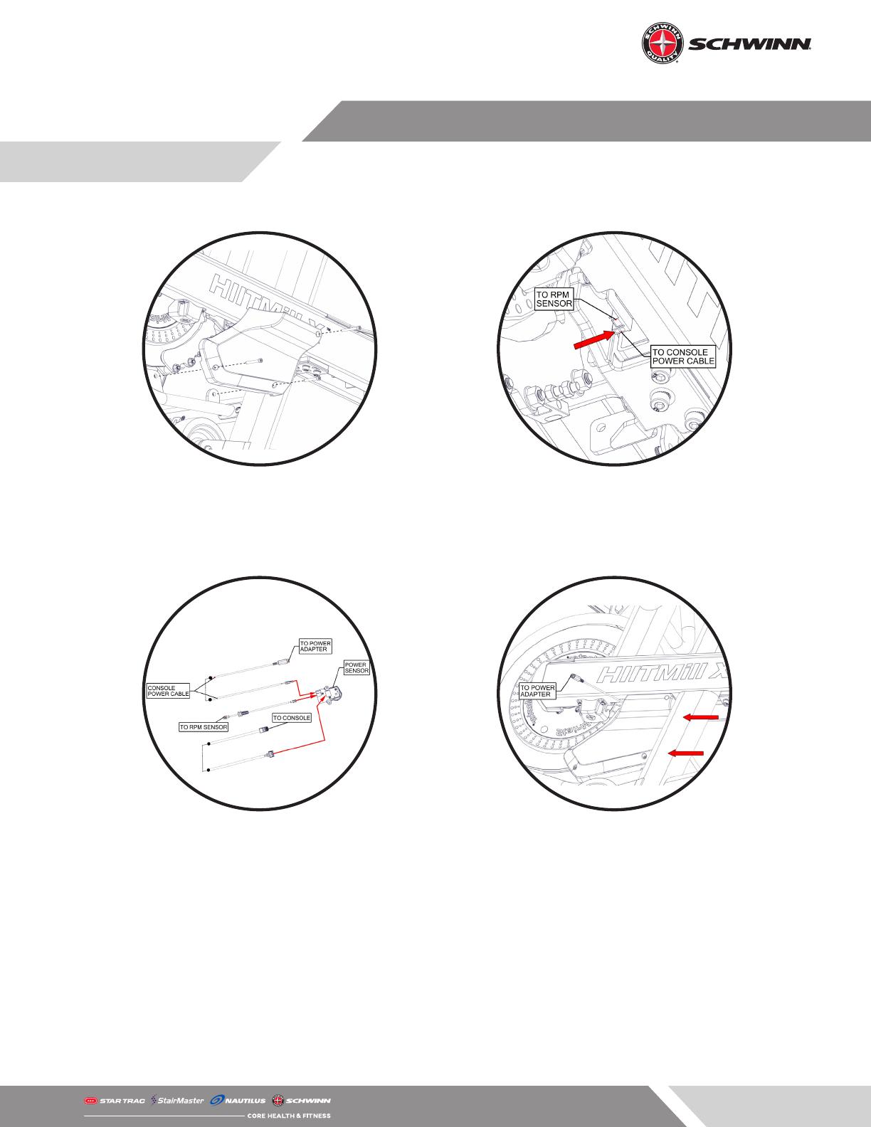
STEP 1: Remove the brake cover using a 4mm allen
key to remove the three (3) M5 x 50mm screws se-
curing the brake cover to the unit.
STEP 2: Connect the Console Power Cable to the
empty 2-pin port on the Power Sensor as indicated
by the arrow, then reinstall the brake covers.
WARNING: When reinstalling the brake covers, en-
sure that no cables are touching the ywheel.
STEP 3: The Power Sensor calibration must be run on
the console before working out after reinstalling the
power sensor. To calibrate the Power Sensor:
A. Push the brake adjustment lever all the way for-
ward (away from the user).
B. Press and hold the level up, level down, and clock
buttons at the same time for 5-10 seconds.
C. Use the down arrow to navigate to page 6, then
push the clock button to set the zero-point angle.
D. Press the back button located between the up/
down arrow buttons to return to the main workout
screen.
STEP 4: Route the end of the Console Power Cable
out of the gap between the frame and the brake
cover, then plug the power adapter into the Console
Power Cable. Finally, use two cable ties to secure
the power adapter and Console Power Cable to the
frame as indicated by the arrows.
Install
Page 8
620-8587 Rev. C
HIIT Rower
TO ROWER
TO WALL
STEP 1: Install the power cord into the power adapter.
STEP 2: Insert the end of the power adapter into
the power inlet located on the console mast.
TO WALL
STEP 3: Route the power adapter cable as shown in image right, use the zip ties included with the power
kit to secure the cable to the HIIT Rower where indicated by the arrows.
STEP 4: After routing the cable, plug the power cable into the wall.
  • Page 1 1
  • Page 2 2
  • Page 3 3
  • Page 4 4
  • Page 5 5
  • Page 6 6
  • Page 7 7
  • Page 8 8

Stairmaster HIITMill 9-4590 Owner's manual

Type
Owner's manual

Ask a question and I''ll find the answer in the document

Finding information in a document is now easier with AI