Page is loading ...

Revised 02/04/20
09.10150 Rev. 02

If you need to contact an authorized Ventrac dealer for information on servicing your product,
always provide the product model and serial numbers.
Please ll in the following information for future reference. See the picture(s) below to nd the
location of the identication numbers. Record them in the spaces provided.
Date of Purchase: __________________________________________________________________
Dealer: ___________________________________________________________________________
Dealer Address: ____________________________________________________________________
____________________________________________________________________
Dealer Phone Number: ______________________________________________________________
Dealer Fax Number: ________________________________________________________________
Model # (A): ___________________________
Serial # (B): ____________________________
Afx Part/Serial Number label here.
Venture Products Inc. reserves the right to make changes
in design or specications without obligation to make like
changes on previously manufactured products.
BB
AA

TABLE OF CONTENTS
3
Product Description ................................................................................................................................ 5
Why Do I Need an Operator’s Manual? .................................................................................................5
Using Your Manual .................................................................................................................................6
Manual Glossary ....................................................................................................................................6
General Safety Procedures .................................................................................................................... 7
Training Required ...................................................................................................................................7
Personal Protective Equipment Requirements ......................................................................................7
Operation Safety ....................................................................................................................................7
Preventing Accidents ..............................................................................................................................8
Keep Riders O ......................................................................................................................................8
Operating On Slopes ..............................................................................................................................9
Roadway Safety .....................................................................................................................................9
Truck Or Trailer Transport ......................................................................................................................9
Maintenance .........................................................................................................................................10
Fuel Safety ...........................................................................................................................................10
Hydraulic Safety ................................................................................................................................... 11
NB200 Safety Procedures ....................................................................................................................12
Setup Instructions for Brine System ..................................................................................................... 13
Operational Control Locations ..............................................................................................................18
Pump Switch (A) ..................................................................................................................................18
On/O Control Valve (B) ......................................................................................................................18
Pressure Regulating Valve (C) ............................................................................................................. 18
Hand Held Spray Gun (D) ....................................................................................................................18
Outer Spray Nozzle Valves (E) ............................................................................................................18
Daily Inspection .................................................................................................................................... 19
Operating Procedure ............................................................................................................................ 19
Spraying Width ..................................................................................................................................... 19
Pressure Regulation .............................................................................................................................19
Brine System Pressure Settings ..........................................................................................................19
Cleaning and General Maintenance.....................................................................................................20
Cleaning the Filter Element .................................................................................................................. 20
Cleaning the Nozzles ...........................................................................................................................20
Draining and Flushing the Brine System .............................................................................................. 21
Storage Between Snow Events ............................................................................................................21
Removal of Brine Tank .........................................................................................................................22

TABLE OF CONTENTS
Dimensions ..........................................................................................................................................23
Features ...............................................................................................................................................23
Tank Base Frame Mount ......................................................................................................................24
Brine Tank & Mounting Straps ..............................................................................................................26
Pump & Pump Mount, Spray Gun & Mount, Pump Switch ..................................................................28
Brine Control Valves, Intake, & Return Hose Circuit ............................................................................30
Rear Supply Hose, Center Nozzle Hose, & Center Nozzles ................................................................ 32
Left & Right Outer Nozzles ...................................................................................................................34

The NB200 Brine system features a 20 gallon (75.7 liter) tank, rear mounted nozzles, and a hand held spray
gun. The nozzles distribute brine in a 36 - 48 inch (91.4 - 122 cm) wide spray pattern. The spray gun is useful
for accessing hard to reach areas and features a coiled hose for easy storage and operation.
This manual has been created to help you gain the important knowledge of what is needed to safely
operate, maintain, and service your machine. It is divided into sections for convenient reference of the
appropriate section.
You must read and understand the operator’s manual for each piece of Ventrac equipment you own. Read-
ing the operator’s manual will help you become familiar with each specic piece of equipment. Under-
standing the operator’s manual will help you, as well as others, avoid personal injury and/or damage to the
equipment. Keep this manual with the machine at all times. The manual should remain with the machine
even if it is sold. If this manual becomes damaged or unreadable, it should be replaced immediately. Con-
tact your local Ventrac dealer for a replacement.
When using a Ventrac attachment, be sure to read and follow the safety and operating instructions of both
the power unit and the attachment being used to ensure the safest operation possible.
The information in this manual provides the operator with the safest procedures to operate the machine
while getting the maximum use out of the unit. Failure to follow the safety precautions listed in this manual
may result in personal injury and/or damage to the equipment.
V
enture Products Inc. is pleased to provide you with your new
Ventrac brine system! We hope that Ventrac equipment will
provide you with a ONE Tractor Solution.

INTRODUCTION
Throughout this manual, you will encounter special messages and symbols that identify potential safety
concerns to help you as well as others avoid personal injury or damage to the equipment.
This symbol identies potential health and
safety hazards. It marks safety precautions.
Your safety and the safety of others is involved.
There are three signal words that describe the level of safety concern: Danger, Warning, and Caution.
Safety should always be the #1 priority when working on or operating equipment. Accidents are more likely
to occur when proper operating procedures are not followed or inexperienced operators are involved.
Note: Right-Hand and Left-Hand orientations may be referred to at dierent places throughout this manual.
Right-Hand and Left-Hand is determined as if sitting on the power unit seat facing forward.
Indicates a potentially hazardous situation
which, if not avoided, could result in death or
serious injury.
Indicates an imminently hazardous situation
which, if not avoided, will result in death or
serious injury. This signal word is limited to the
most extreme cases.
Indicates a potentially hazardous situation
which, if not avoided, may result in minor or
moderate injury and/or property damage. It may
also be used to alert against unsafe practices.
A Ventrac tractor or other Ventrac engine powered device that may be operated by itself or
with an attachment or accessory.
A piece of Ventrac equipment that requires a Power Unit for operation.
A device that attaches to a Power Unit or Attachment to extend its capabilities.
Describes any “Attachment” or “Accessory” that is used in conjunction with a power unit.

• The owner of this machine is solely responsible for properly training the operators.
• The owner/operator is solely responsible for the operation of this
machine and prevention of accidents or injuries occurring to him/her-
self, other people, or property.
• Do not allow operation or service by children or untrained personnel.
Local regulations may restrict the age of the operator.
• Before operating this machine, read the operator’s manual and under-
stand its contents.
• If the operator of the machine cannot understand this manual, then it
is the responsibility of this machine’s owner to fully explain the material
within this manual to the operator.
• Learn and understand the use of all controls.
• Know how to stop the power unit and all attachments quickly in the event of an emergency.
It is the responsibility of the owner to be sure that the operators use the proper personal protective equip-
ment while operating the machine. Required personal protective equipment includes, but is not limited to,
the following list.
• Wear a certied ear protection device to prevent loss of hearing.
• Prevent eye injury by wearing safety glasses while operating the machine.
• Closed toe shoes must be worn at all times.
• Long pants must be worn at all times.
• When operating in dusty conditions, it is recommended that a dust mask be worn.
• Inspect machine before operation. Repair or replace any damaged, worn, or missing parts. Be sure
guards and shields are in proper working condition and are secured in place. Make all necessary
adjustments before operating machine.
• Some pictures in this manual may show shields or covers opened or removed in order to clearly illustrate
any instructions. Under no circumstance should the machine be operated without these devices in place.
• Alterations or modications to this machine can reduce safety and could cause damage to the machine.
Do not alter safety devices or operate with shields or covers removed.
• Before each use, verify that all controls function properly and inspect all safety devices. Do not operate
if controls or safety devices are not in proper working condition.
• Check parking brake function before operating. Repair or adjust parking brake if necessary.
• Observe and follow all safety decals.
• All controls are to be operated from the operator’s station only.
• Always wear a seat belt if the machine has a roll cage/bar installed and in upright position.
• Ensure the attachment or accessory is locked or fastened securely to the power unit before operating.
• Ensure that all bystanders are clear of the power unit and attachment before operating. Stop machine if
someone enters your work area.
• Always be alert to what is happening around you, but do not lose focus on the task you are performing.
Always look in the direction the machine is moving.
• Look behind and down before backing up to be sure of a clear path.
• If you hit an object, stop and inspect the machine. Make all necessary repairs before operating machine again.
• Stop operation immediately at any sign of equipment failure. An unusual noise can be a warning of equipment
failure or a sign that maintenance is required. Make all necessary repairs before operating machine again.

SAFETY
General Safety Procedures
for Ventrac Power Units, Attachments, & Accessories
• If equipped with a high/low range feature, never shift between high and low range while on a slope.
Always move the machine to level ground and engage the parking brake before shifting range.
• Do not leave machine unattended while it is running.
• Always park the machine on level ground.
• Always shut o engine when connecting attachment drive belt to the power unit.
• Never leave the operator’s station without lowering the attachment to the ground, setting the parking
brake, shutting o the engine, and removing the ignition key. Make sure all moving parts have come to
a complete stop before dismounting.
• Never leave equipment unattended without lowering the attachment to the ground, setting the parking
brake, shutting o the engine, and removing the ignition key.
• Only operate in well-lit conditions.
• Do not operate when there is a risk of lightning.
• Never direct the discharge of any attachment in the direction of people, buildings, animals, vehicles, or
other objects of value.
• Never discharge material against a wall or obstruction. Material may ricochet back towards the operator.
• Use extra caution when approaching blind corners, shrubs, trees, or other objects that may obscure vision.
• Do not run the engine in a building without adequate ventilation.
• Do not touch the engine or the muer while the engine is running or immediately after stopping the engine.
These areas may be hot enough to cause a burn.
• Do not change the engine governor settings or over-speed the engine. Operating engine at excessive speed
may increase the hazard of personal injury.
• To reduce the hazard of re, keep the battery compartment, engine, and muer areas free of grass, leaves,
excessive grease, and other ammable materials.
• Clear working area of objects that might be hit or thrown from machine.
• Keep people and pets out of working area.
• Know the work area well before operation. Do not operate where traction or
stability is questionable.
• Reduce speed when you are operating over rough ground.
• Equipment can cause serious injury and/or death when improperly used.
Before operating, know and understand
the operation and safety of the power
unit and the attachment being used.
• Do not operate machine if you are not in good physical and
mental health, if you will be distracted by personal devices, or are
under the inuence of any substance which might impair deci-
sion, dexterity, or judgment.
• Children are attracted to machine activity. Be aware of children
and do not allow them in the working area. Turn o the machine if
a child enters the work area.
• Only allow the operator on the power unit. Keep riders o.
• Never allow riders on any attachment or accessory.

SAFETY
General Safety Procedures
for Ventrac Power Units, Attachments, & Accessories
• Slopes can cause loss-of-control and
tip-over accidents, which can result in
severe injury or death. Be familiar with the
emergency parking brake, along with the
power unit controls and their functions.
• If power unit is equipped with a fold down
roll bar, it must be locked in the upright
position when operating on any slope.
• Use low range (if equipped) when operating
on slopes greater than 15 degrees.
• Do not stop or start suddenly when operating on slopes.
• Never shift between high and low range while on a slope. Always move the power unit to level ground
and engage the parking brake before shifting range or placing the power unit in neutral.
• Variables such as wet surface and loose ground will reduce the degree of safety. Do not drive where
machine could lose traction or tip over.
• Keep alert for hidden hazards in the terrain.
• Stay away from drop-os, ditches, and embankments.
• Sharp turns should be avoided when operating on slopes.
• Pulling loads on hills decreases safety. It is the responsibility of the owner/operator to determine loads
that can safely be controlled on slopes.
• Transport machine with attachment lowered or close to the ground to improve stability.
• While operating on slopes, drive in an up and down direction when possible. If turning is necessary
while driving across slopes, reduce speed and turn slowly in the downhill direction.
• Assure a sucient supply of fuel for continuous operation. A minimum of one-half tank of fuel is recommended.
• Operate with safety lights when operating on or near roadways.
• Obey all state and local laws concerning operation on roadways.
• Slow down and be careful of trac when operating near or crossing roadways. Stop before crossing
roads or sidewalks. Use care when approaching areas or objects that may obscure vision.
• If there is doubt of safety conditions, discontinue machine operation until a time when
operation can be performed safely.
• When operating near or on roadways, have a Slow Moving Vehicle Emblem clearly
displayed.
• Use care when loading or unloading machine into a truck or trailer.
• Use full width ramps for loading machine into a truck or trailer.
• The parking brake is not sucient to lock the machine during transport. Always secure the power unit
and/or attachment to the transporting vehicle securely using straps, chains, cable, or ropes. Both front
and rear straps should be directed down and outward from the machine.
• Shut o fuel supply to power unit during transport on truck or trailer.
• If equipped, turn the battery disconnect switch to the O position to shut o electrical power.

SAFETY
General Safety Procedures
for Ventrac Power Units, Attachments, & Accessories
• Keep all safety decals legible. Remove all grease dirt, and debris from safety decals and instructional labels.
• If any decals are faded, illegible, or missing, contact your dealer promptly for replacements.
• When new components are installed, be sure that current safety decals are axed to the replacement
components.
• If any component requires replacement, use only original Ventrac replacement parts.
• Always turn the battery disconnect to the O position or disconnect the battery before performing any
repairs. Disconnect the negative terminal rst and the positive terminal last. Reconnect the positive
terminal rst and the negative terminal last.
• Keep all bolts, nuts, screws, and other fasteners properly tightened.
• Always lower the attachment to the ground, engage parking brake, shut o engine, and remove the
ignition key. Make sure all moving parts have come to a complete stop before cleaning, inspection,
adjusting or repairing.
• If the power unit, attachment, or accessory requires repairs or adjustments not instructed in the operator’s
manual, the power unit, attachment, or accessory must be taken to an authorized Ventrac dealer for service.
• Never perform maintenance on the power unit and/or attachment if someone is in the operator’s station.
• Always use protective glasses when handling the battery.
• Check all fuel lines for tightness and wear on a regular basis. Tighten or repair them as needed.
• To reduce the hazard of re, keep the battery compartment, engine, and muer areas free of grass,
leaves, and excessive grease.
• Do not touch the engine, the muer, or other exhaust components while the engine is running or imme-
diately after stopping the engine. These areas may be hot enough to cause a burn.
• Allow the engine to cool before storing and do not store near an open ame.
• Do not change the engine governor settings or over-speed the engine. Operating engine at excessive
speed may increase the hazard of personal injury.
• Springs may contain stored energy. Use caution when disengaging or removing springs and/or spring
loaded components.
• An obstruction or blockage in a drive system or moving/rotating parts may cause a buildup of stored
energy. When the obstruction or blockage is removed, the drive system or moving/rotating parts may
move suddenly. Do not attempt to remove an obstruction or blockage with your hands. Keep hands,
feet, and clothing away from all power-driven parts.
• Dispose of all uids in accordance with local laws.
• To avoid personal injury or property damage, use extreme care in handling gasoline. Gaso-
line is extremely ammable and the vapors are explosive.
• Do not refuel machine while smoking or at a location near ames or sparks.
• Always refuel the machine outdoors.
• Do not store machine or fuel container indoors where fumes or fuel can reach an open
ame, spark, or pilot light.
• Only store fuel in an approved container. Keep out of reach of children.
• Never ll containers inside a vehicle or on a truck or trailer bed with a plastic liner. Always place containers
on the ground away from your vehicle before lling.
• Remove machine from the truck or trailer and refuel it on the ground. If this is not possible, refuel the
machine using a portable container, rather than from a fuel dispenser nozzle.
• Never remove fuel cap or add fuel with the engine running. Allow engine to cool before refueling.
• Never remove fuel cap while on a slope. Only remove when parked on a level surface.
• Replace all fuel tank and container caps securely.

SAFETY
General Safety Procedures
for Ventrac Power Units, Attachments, & Accessories
• Do not overll fuel tank. Only ll to bottom of fuel neck, do not ll fuel neck full. Overlling of fuel tank could
result in engine ooding, fuel leakage from the tank, and/or damage to the emissions control system.
• If fuel is spilled, do not attempt to start the engine. Move the power unit away from the fuel spill and
avoid creating any source of ignition until fuel vapors have dissipated.
• If the fuel tank must be drained, it should be drained outdoors into an approved container.
• Dispose of all uids in accordance with local laws.
• Check all fuel lines for tightness and wear on a regular basis. Tighten or repair them as needed.
• The fuel system is equipped with a shut-o valve. Shut o the fuel when transporting the machine to
and from the job, when parking the machine indoors, or when servicing the fuel system.
• Make sure all hydraulic connections are tight and all hydraulic hoses and tubes are in good condition.
Repair any leaks and replace any damaged or deteriorated hoses or tubes before starting the machine.
• Hydraulic leaks can occur under high pressure. Hydraulic leaks require special care and attention.
• Use a piece of cardboard and a magnifying glass to locate sus-
pected hydraulic leaks.
• Keep body and hands away from pinhole leaks
or nozzles that eject high pressure hydraulic uid.
Hydraulic uid escaping under high pressure can
penetrate the skin causing serious injury, leading to
severe complications and/or secondary infections
if left untreated. If hydraulic uid is injected into the
skin, seek immediate medical attention no matter
how minor the injury appears.
• Hydraulic system may contain stored energy. Before performing maintenance or repairs on the hydraulic
system, remove attachments, engage parking brake, disengage weight transfer system (if equipped),
shut o engine, and remove ignition key. To relieve pressure on the auxiliary hydraulic system, shut o the
power unit engine and move the hydraulic control lever left and right before disconnecting the auxiliary
hydraulic quick couplers.
• Dispose of all uids in accordance with local laws.

SAFETY
• Brine tank frame must be properly secured to the power unit before operating.
• Do not point the spray gun at people or animals.
• Do not use any products containing petroleum or petroleum by-products, as they can cause damage to
system components.
• Always turn o electrical power to the pump and shut o the power unit before performing maintenance
or repairs on the brine system.
• Wear safety goggles or a face shield when servicing brine system hoses, nozzles, or spray wand.
• When using a commercial deicing solution, follow the manufacturer’s recommendations for personal
protective equipment and rst aid procedures.
• If you are making your own salt brine solution, wear eye goggles or a full face shield and gloves when
mixing the brine solution and when lling the brine tank. Avoid contact with eyes, skin, and clothing.
• Salt brine can cause irritation to the eyes and the skin. In case of eye contact, immediately ush eyes
with plenty of water for 10 minutes. Seek medical attention if irritation persists. In case of skin contact,
wash with mild soap and water.
• Ingestion of salt brine may cause nausea, vomiting, diarrhea, tissue irritation, fever, etc. If a large
amount of salt brine is ingested, drink large amounts of water or milk. If any symptoms develop, seek
immediate medical attention.
• In case of accidental release, follow the manufacturer’s recommendations for containment and cleanup
when using a commercial deicing solution. If using your own salt brine solution, rinse away small spills
with water. For larger spills, contain the liquid and vacuum up or absorb the liquid for proper disposal.
Rinse the spill area with water.

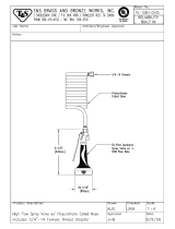
Installation Time (estimated) 2 hours
1.
To prevent thread galling of stainless steel hard-
ware, lubricate the bolt threads with a lithium
complex NLGI #2 grease and use hand tools to
tighten. Do not use air or electric power tools as
this increases the potential of thread galling.
Park the power unit on a level surface.
2. Shut o the power unit’s engine, engage the park-
ing brake, and remove the key from the ignition.
3. Press the button on the battery disconnect switch.
4.
WARNING
Failure to allow the engine and muer to cool
down suciently could result in severe burns from
contact with hot engine components.
Allow the engine and muer to cool completely
before proceeding.
5. If the power unit is equipped with a storage bas-
ket kit, the storage basket must be removed.
6. Remove the operator cushion from the power unit.
7. Remove the pump belt drive cover from the
engine frame on the power unit.
8. Remove the left center fender platform (A).
9.
A
B
Remove the left frame side cover (B).
10. Remove the box of parts and hardware from the
crate. Leave the brine tank assembly crated until
the power unit has been tted with brine nozzles
and hoses.
11. Shape one of the 3/4” cushioned clamps so that
the brine hose will slide through without pinch-
ing. Install the clamp (A) onto the left side of the
main tower frame using the original hardware.
Do not tighten.
12.
A
B
Shape one of the 3/4” cushioned clamps so that
the pump harness connector will slide through.
Install the clamp (B) on the right side of the
main tower frame using the original hardware.
Do not tighten.
13. Remove the nut from the bolt that fastens the
left rear fender to the rear ange on the main
frame. Install the left brine nozzle mount onto
the bolt and loosely reinstall the nut.
Fasten the brine nozzle mount to the left rear
fender using 2) 1/4 x 3/4” bolts, washers, and
ange nuts. Torque all three mounting bolts to
72 in-lbs (8 Nm).

SETUP
14. Remove the nut from the bolt that fastens the
right rear fender to the rear ange on the main
frame. Install the right brine nozzle mount onto
the bolt and loosely reinstall the nut.
Fasten the brine nozzle mount to the right rear
fender using 2) 1/4 x 3/4” bolts, washers, and
ange nuts. Torque all three mounting bolts to
72 in-lbs (8 Nm).
15. Install the center brine nozzle mount onto the
main frame in front of the operator platform
using 2) 1/4 x 1” bolts, washers, and ange nuts.
Torque to 72 in-lbs (8 Nm).
16. Locate the hose assembly with 3) hoses and a
tee tting.
To left brine To left brine
nozzle assemblynozzle assembly
To left front To left front
tower posttower post
Under engine mount Under engine mount
to right brine nozzle to right brine nozzle
assemblyassembly
17.
Short hoseShort hose
Long hoseLong hose
Route the long hose under the engine mount,
in front of the fuel lines, through the slot in the
frame, and back toward the right brine nozzle
mount. Route the short hose back toward the
left brine nozzle mount.
18. Pull the end of the long hose (C) out below the
right rear cover and connect to the barbed tting
for the right brine nozzle assembly.
19.
C
D
Push the hose connections up between the
fender and rear cover. Place a 3/4” cushioned
clamp (D) around the two hoses and fasten to
the rear fender using a 1/4 x 1/2” bolt, washer,
and ange nut. Torque to 72 in-lbs (8 Nm).

SETUP
20. Repeat steps 18 & 19 to connect the short hose
to the left brine nozzle assembly.
21. Place the hose retainer bracket over the hose
that runs from left to right under the engine
mount. Ensure the hose is captured by all three
hooks on the bracket.
Long Long
hosehose
Short Short
hosehose
Fasten the bracket to the frame using 2) 1/4 x
3/4” bolts, washers, and ange nuts. Torque to
72 in-lbs (8 Nm).
22. Install the rubber grommet (E) into the hole in
the main frame cross plate.
E
23. Locate the hose with a Tee tting in one end.
Route the end without the tting down through
the cutout for the hydraulic hoses in the left side
of the main frame.
24. Route the hose through the grommet in the rear
of the main frame and connect to the barbed t-
ting on the center brine nozzle assembly.
25. Use a 1/2” cushioned clamp (F) to secure the hose
to the main frame below the fuel tank. Fasten the
clamp to the frame using a 1/4 x 1” bolt, washer,
and ange nut. Use two zip ties (G) to fasten the
hose to the rear cross plate next to the fuel tank.
Torque the clamp bolt to 72 in-lbs (8 Nm).
F
G

SETUP
26. Connect the hose (H) from the left and right brine
nozzle assemblies to the tee on the hose tting.
27.
H
Unfasten the crate brackets from the crate and
remove the brine tank assembly.
28. Remove the crate brackets from the tank frame.
Save the hardware for reuse.
29. Install the left (I) and right (J) rear accessory
mounts onto the tank frame using the hardware
from the crate brackets. Do not tighten.
NOTE: the power unit mounting anges must be
toward the outer edge of the frame.
30.
I
J
Place the brine tank assembly onto the accessory
mount/shield frame on the front of the power unit.
31. Fasten the left and right rear accessory mounts
to the anges of the accessory mount/shield
frame using a 5/16 x 3/4” bolt, washer, and
ange nut for each mount. Do not tighten.
32. Install the front accessory mount bracket (K)
onto the brine tank frame and the front ange of
the accessory mount/shield frame using 4) 5/16
x 3/4” bolts, washers, and ange nuts. Torque
the bolts to 149 in-lbs (17 Nm).
33.
K
Torque the bolts for the left and right rear mount-
ing brackets to 149 in-lbs (17 Nm).
34. Apply thread sealant to the tting (L) on the
spray gun hose and install into the front port on
the on/o control valve.
35.
L
Insert the spray gun nozzle into the front holder
and press the spray gun into the plastic clip next
to the on/o control valve.

SETUP
36. Route the hose from the bottom port of the on/
o control valve through the clamp (M) on the
left side of the main tower frame and down past
the engine into the left frame area. Connect the
hose to the tee tting from the brine nozzles.
37.
M
Rotate the clamp to hold the hose in proper align-
ment and torque the bolt to 72 in-lbs (8 Nm).
38. Route the connector on the pump harness
through the clamp on the right side of the main
tower and down past the engine into the right
frame area.
39. Locate the switch location
N
(N) in the right dash panel.
Shining a light from beneath
the dash will help show the
area of the decal to remove.
40. Using a utility knife, cut the
decal to match the hole in
the dash panel.
41. Install the switch (O) into
the dash cutout with the
light toward the front of the
power unit.
42.
O
Locate the brine system wire harness and install
the switch connector onto the switch. Hold the
switch in place with one hand while installing the
switch connector.
43. Locate the female MP280 connector (P) with gray
(A-058) and black (A-116) wires behind the fuse
panel. Remove the cap and connect to the male
MP280 connector on the brine system harness.
44.
P
Q
Connect the female MP280 connector (Q) on
the brine system harness to the male MP280
connector on the pump harness.
45. Use a zip tie to fasten the brine system harness
to the main harness behind the fuse panel.
46. Rotate the clamp on the tower frame to hold the
wire harness in proper alignment and torque the
bolt to 72 in-lbs (8 Nm).
47. Install the 15 amp fuse into position 8 in the fuse
panel and reinstall the fuse panel cover.
48. Reinstall the left frame side cover. Torque bolts
to 149 in-lbs (17 Nm).
49. Reinstall the left fender center platform. Torque
bolts to 149 in-lbs (17 Nm).
50. Reinstall the pump belt drive cover. Torque the
bolts to 72 in-lbs (8 Nm).
51. Place the operator cushion back on the power unit.
52. Reset the battery disconnect switch.
Installation is complete.

Use the following images to help identify the locations
of operational controls. The letter next to each control
can be referenced to the list that follows these images.
A
B
C
D
E
E
Pressing the top portion of the pump switch turns on
the brine system pump. The pump switch light will
turn on when electrical power is being supplied to
the pump. Pressing the bottom portion of the switch
turns the pump o.
The on/o control valve turns on or shuts o ow
to the spray nozzles. Rotate the handle forward or
backward 90 degrees to turn on the ow of brine
solution to the spray nozzles. Rotate the handle to
the vertical position to shut o the ow of brine solu-
tion to the spray nozzles. Brine solution ows through
the control valve to the pressure regulating valve and
the spray gun with the handle in all positions.
The pressure regulating valve controls the pressure
of the brine system. Turning the handle clockwise
increases system pressure. Turning the handle
counterclockwise decreases system pressure. The
valve is equipped with a pressure relief bypass that
returns excess brine solution to the main tank.
The spray gun is equipped with a 15 foot (4 meter)
coiled hose and is used to treat small or hard to
reach areas. Squeeze the handle to activate the
spray gun. The handle can be locked in the On posi-
tion by pushing the handle lock forward.
The spray pattern can be adjusted by rotating the
nozzle tip on the spray gun until the desired spray
pattern is achieved.
The outer spray nozzle valves control the ow of
brine solution to the outer nozzle on each side of the
power unit.

1.
Always set the parking brake, shut o power
unit engine, remove the ignition key, and ensure
all moving parts have come to a complete stop
before inspecting components, or attempting
any repair or adjustment.
Park machine on a level surface, with the engine
shut o and all uids cold.
2. Perform a visual inspection of both the power
unit and the brine system. Look for loose or
missing hardware, damaged components, or
signs of wear.
3. Inspect hoses and ttings to ensure tight, leak
free connections.
4. Check nozzles for even spray pattern.
5. Refer to the power unit operator’s manual.
Check the power unit’s engine oil, hydraulic oil,
tire pressure, and fuel level. Add uid or service
as required.
6. Test the power unit’s operator safety interlock
system*.
Before operation, perform daily inspection, set the
pressure regulating valve to the desired pressure,
and turn the outer spray nozzles on or o to set the
desired overall width of the spray pattern.
Move the machine into position and turn on the
brine system pump. Move the on/o valve handle
to the On position to start the ow of brine solution.
Drive forward following the sidewalk or other treat-
ment area. When the end of the treatment area is
reached, stop the machine and move the on/o
valve handle to the O position.
When treating an area that is wider than the spray
pattern, spray in a back and forth pattern until the
entire area has been treated.
Use the spray gun to treat steps and hard to reach
areas. Move the on/o valve handle to the O posi-
tion. Park the power unit close to the treatment area
and engage the parking brake. Use the spray gun to
treat the area, then return the spray gun to its stor-
age position.
The spraying width can be adjusted to match the
width of the sidewalk being treated by turning the
left and right outer spray nozzles on or o.
Both valves On 4 feet (122 cm)
One valve On, one valve 3-1/2 feet (106.7 cm)
Both valves 3 feet (91.4 cm)
Adjusting the pressure varies the ow rate through
the nozzles. Rotate the handle on the pressure reg-
ulating valve to increase or decrease the pressure
to the desired setting. Tighten the plastic lock nut
against the handle to lock the handle in the desired
position. Note that pressures will change when the
on/o valve is turned on and o as well as when the
outer spray nozzles are turned on and o.
The following chart gives the recommended brine
system pressure settings based on spraying width
and power unit speed. Adjustments may be neces-
sary to achieve your desired application results.
3 feet
(91.4 cm)
15 PSI 25 PSI 30 PSI
3-1/2 feet
(106.7 cm)
15 PSI 25 PSI
Maximum
Pressure
4 feet
(122 cm)
15 PSI
Maximum
Pressure
Maximum
Pressure

For best results, and to maintain the nish of the
power unit and brine system, clean or wash the brine
system and power unit to remove dirt, brine and salt
deposits, and snow or ice accumulations.
To maintain the nish of the power unit and attach-
ment, thoroughly wash the equipment after each
use to remove any corrosive agents (e.g., salt). Fail-
ure to clean the equipment may result in corrosion
of (including but not limited to) steel, aluminum, and
electrical components. Equipment that will experi-
ence repeated exposure to corrosive agents should
be pretreated with a corrosion preventative.
1. Turn o electrical power to the brine system pump.
2. Place a rag underneath the lter (A) to catch any
spills or drips.
3.
A
Loosen the lter cap slightly, then wait for sev-
eral seconds to allow brine solution to drain
back into the tank.
4. Remove the lter cap from the lter.
5. Carefully remove the lter screen from the lter
head and rinse under clean running water to
remove debris.
6. Insert the lter screen into the lter head.
7. Ensure the gasket is properly seated in the lter
cap and reinstall the cap onto the lter head.
1. Park the power unit on a level surface.
2. Shut o the power unit’s engine, engage the park-
ing brake, and remove the key from the ignition.
3. Remove the nozzle tip (A) and lter screen from
the nozzle base by unthreading the nut (B) from
the base.
4.
A
B
Rinse the lter screen under clean running water
to remove debris.
5. Reinstall the lter screen and nozzle tip onto the
nozzle base. Do not overtighten.
Always set the parking brake, shut o power
unit engine, remove the ignition key, and ensure
all moving parts have come to a complete stop
before inspecting components or attempting any
repair or adjustment.
If any component requires replacement, use only
original Ventrac replacement parts.
/