Notifier NFC-50-100C Voice Evacuation and Emergency Communications System Owner's manual
- Category
- Fire protection
- Type
- Owner's manual
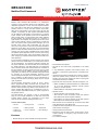
Notifier NFC-50-100C Voice Evacuation and Emergency Communications System is a multipurpose emergency voice evacuation panel for fire applications, mass notification applications, or both. It delivers 50 or 100 watts of audio power for distribution to up to eight speaker circuits. It comes with a single speaker circuit and a built-in 50-watt, 25V amplifier that can be expanded to two speaker circuits and an additional 50 watts of audio power with an optional NFC-BDA-25/70V amplifier. An optional NFC-CE6 module can be added to upgrade the system to a maximum of eight speaker circuit outputs. All speaker output circuits can be wired in either Class B or Class A configuration.
Notifier NFC-50-100C Voice Evacuation and Emergency Communications System is a multipurpose emergency voice evacuation panel for fire applications, mass notification applications, or both. It delivers 50 or 100 watts of audio power for distribution to up to eight speaker circuits. It comes with a single speaker circuit and a built-in 50-watt, 25V amplifier that can be expanded to two speaker circuits and an additional 50 watts of audio power with an optional NFC-BDA-25/70V amplifier. An optional NFC-CE6 module can be added to upgrade the system to a maximum of eight speaker circuit outputs. All speaker output circuits can be wired in either Class B or Class A configuration.


-
 1
1
-
 2
2
-
 3
3
-
 4
4
-
 5
5
-
 6
6


Notifier NFC-50-100C Voice Evacuation and Emergency Communications System Owner's manual
- Category
- Fire protection
- Type
- Owner's manual
Notifier NFC-50-100C Voice Evacuation and Emergency Communications System is a multipurpose emergency voice evacuation panel for fire applications, mass notification applications, or both. It delivers 50 or 100 watts of audio power for distribution to up to eight speaker circuits. It comes with a single speaker circuit and a built-in 50-watt, 25V amplifier that can be expanded to two speaker circuits and an additional 50 watts of audio power with an optional NFC-BDA-25/70V amplifier. An optional NFC-CE6 module can be added to upgrade the system to a maximum of eight speaker circuit outputs. All speaker output circuits can be wired in either Class B or Class A configuration.
Ask a question and I''ll find the answer in the document
Finding information in a document is now easier with AI
Related papers
-
Notifier N-ANN-S/PG Serial Parallel Printer Interface Module Owner's manual
-
Notifier RP-2002-E Agent Release Control Panel Owner's manual
-
-
-
-
-
-
Notifier NFV-25/50ZST Zoned System Voice User manual
-
Notifier AFP-200 User manual
-
Other documents
-
Fire-Lite Alarms ANN-I/O LED Driver Module Owner's manual
-
-
Honeywell ECC-50/100 User manual
-
Potter 70V-1000 User manual
-
Bosch PRA-FRP3-US Call Point User manual
-
HID ADC-AC-X200 Installation guide
-
Wheelock ET90-2475C User manual
-
Potter Guardian QR700 User manual
-
-
 Simplex MINIPLEX 4100ES Series Installation guide
