Page is loading ...

HD3070
Plasma Arc Cutting System
with Automatic Gas Console
Product Configuration Manual
802310 - Revision 4

Revision 4 - January 2000
HD3070
Plasma Arc Cutting System
with Automatic Gas Console
Product Configuration Manual
PM-231
© Copyright 2000 Hypertherm, Inc.
All Rights Reserved
Htpertherm and HyDefinition are trademarks of Hypertherm, Inc. and may be
registered in the United States and/or other countries
Hypertherm, Inc.
Hanover, NH USA
http://www.hypertherm.com
email: [email protected]

Hypertherm Offices Worldwide
:
Hypertherm, Inc.
Etna Road, P.O. Box 5010
Hanover, NH 03755 USA
Tel.: (603) 643-3441 (Main Office)
Fax: (603) 643-5352 (All Departments)
Tel.: (800) 643-9878 (Technical Service – toll-free in USA and Canada)
Tel.: (800) 737-2978 (Customer Service – toll-free in USA and Canada)
email: [email protected] (General Information)
email: [email protected] (Technical/Customer Services)
Hypertherm Plasmatechnik GmbH
Technologiepark Hanau
Rodenbacher Chaussee 6
D–63457 Hanau-Wolfgang, Germany
Tel.: 49 6181 58 2100
Fax: 49 6181 58 2134
Hypertherm Singapore Pte Ltd
No. 19 Kaki Bukit Road 2
K.B. Warehouse Complex
Singapore 417847
Tel.: 65 841 2489
Fax: 65 841 2490
Hypertherm U.K.
9 Berkeley Court, Manor Park
Runcorn, Cheshire, England WA7 1TQ
Tel.: 44 1928 579 074
Fax: 44 1928 579 604
France
15 Impasse des Rosiers
95610 Eragny, France
Tel.: 33 1 30 37 15 28
Fax: 33 1 30 37 15 79
Hypertherm Italy S.r.L.
Via Torino 2
20123 Milan, Italy
Tel.: 39 02 725 46 312 (Customer Service)
Tel.: 39 02 725 46 314 (Technical Service)
Fax: 39 02 725 46 400 (All Departments)
Hypertherm B.V.
Burg, Haverkampstraat 13
7091 CN Dinxperlo, The Netherlands
Tel.: 31 315 655 866 (Customer Service)
Fax: 31 315 655 886
European Technical Support Organization (ETSO)
Edisonstraat 12
3281 NC Numansdorp, The Netherlands
Tel.: +800 4973 7843 (+800 Hypertherm) – (toll-free Technical Service)
Tel.: 31 186 659494
Fax: 31 186 659495
Japan
Shinjuku Park Tower 30th Floor
3-7-1 Nishi-Shinjuku
Shinjuku-ku, Tokyo
163-1030, Japan
81 03 5326 3142 Tel
81 03 5326 3001 Fax
2/00

1-1HD3070 w/Automatic Gas Console
1 Ordering Procedure
In this section:
Introduction ............................................................................................................... 1-2
Torches ................................................................................................................ 1-2
Cutting Machines ................................................................................................. 1-2
Multi-Torch Systems ................................................................................................. 1-3
Layout of Cutting Machine and HD3070 System ...................................................... 1-4
Ordering Information ................................................................................................. 1-5
Single-System Ordering Procedure .......................................................................... 1-6
Customized Ordering For HD3070 w/Automatic Gas Console ................................. 1-8
1 Power Supply ................................................................................................. 1-8
2 Automatic Gas Console.................................................................................. 1-8
3 RHF Console .................................................................................................. 1-8
4 Leads Between Power Supply and the RHF Console .................................... 1-8
5 Work Cable Between Power Supply and Work Table .................................... 1-10
6 Leads Between Power Supply and Gas Console........................................... 1-10
Torch Configuration................................................................................................... 1-12
13 Leads Between RHF Console and Torch ....................................................... 1-14
14 Off-Valve Assembly ........................................................................................ 1-14
15 Shield Hose .................................................................................................... 1-14
16 Plasma Hose .................................................................................................. 1-14
17 Leads Between Gas Console and Off-Valve Assembly ................................. 1-14
18 Control Cable Between Gas Console and Cutting Machine Interface............ 1-16
19 Control Cable Between Power Supply and Cutting Machine Interface .......... 1-16
20 Current Setpoint Cable ................................................................................... 1-18
21 Timer Counter Cable ...................................................................................... 1-18
22 Remote Current Control (RCC) ...................................................................... 1-18
23 Timer-Counter ................................................................................................ 1-18
1-00

1-2 HD3070 w/Automatic Gas Console
INTRODUCTION
Hypertherm’s HD3070 HyDefinition® plasma cutting system is a precision cutting dual gas
machine-torch system. The microprocessor-controlled system helps to provide extended life
for the torch consumables parts. To achieve consumable long life, all cuts must begin and
end on the plate surface; this allows for the proper ramping of gases and DC current to
extend the life of the nozzle and electrode. The HD3070 system consists of a power supply,
remote high frequency (RHF) console, gas console, off-valve assembly and torch. Optional
units include a timer-counter and a remote current control.
The HD3070 can be configured for either robotic applications or X-Y cutting tables. To
accommodate the different needs of these two types of systems, two different torches are
offered.
TORCHES
PAC184
If ordering for a robotic system, the PAC184 torch with 45° quick disconnect is recom-
mended. This torch, with a pointed front end, is designed to cut in a robotic environment.
PAC186
The PAC186 torch with the straight quick disconnect is more suitable for X-Y cutting tables.
A unique feature to the PAC184 and PAC186 torches is that the torch bodies, quick discon-
nects and mounting sleeves are all interchangeable.
CUTTING MACHINES
If cutting on an X-Y machine, it is extremely critical that the torch drive system has very
accurate vibration-free control of the X, Y, and Z axes. Placing a precision-cutting plasma
system on a cutting machine with poor positioning or poor contouring tolerance, or with
inadequate acceleration and deceleration characteristics will clearly show the effects on the
cut face. The Z-axis of the cutting machine must be controlled to +/-.005 in. Initial height
sensing (IHS) for plate piercing must also be accurate and repeatable to ensure long
consumable life.
Hypertherm recommends HD3070 units be installed on new, high-precision X-Y machines.
For robotic and hard tooling applications, any system that is laser compatible will generally
perform well with the HD3070 system.
12-96

1-3HD3070 w/Automatic Gas Console
MULTI-TORCH SYSTEMS
If more than one torch is required, increase the quantity of each component by the number
of torches to be used.
To specify the correct components for each application, follow the guidelines in this section.

1-4 HD3070 w/Automatic Gas Console
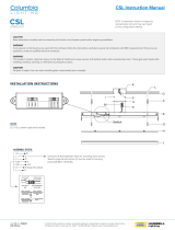
LAYOUT OF CUTTING MACHINE AND HD-3070 SYSTEM
When configuring an HD3070 system(s), it is important to know where each major compo-
nent will be placed. This will vary with the cutting machine manufacturer and with the particu-
lar installation. After the location of the major components has been determined, the inter-
connecting leads and cable lengths can be specified.
It is critical to follow the path that the interconnecting leads will follow and allow for some
slack when specifying their lengths. Do not try to get by with the next shorter length!
Pictured below is a diagram showing an overhead view of a typical precision cutting X-Y
machine. Installations vary, so use this figure as a guide.
Rail Water
Table
Torch
Rail
Bridge
* Cables are usually in a power track or
festoon system. Cable, lead and hose lengths
must allow for routing through the system.
Figure 1-1 Gantry (Bridge) Layout)*

1-5HD3070 w/Automatic Gas Console
ORDERING INFORMATION
The figure below represents an HD3070 plasma system with automatic gas console mounted in a
robotic environment. A complete robotic system is also represented in block diagram form on page
1-7. See pages 1-20 and 1-21 for representations of an HD3070 plasma system with automatic gas
console mounted on an X-Y cutting table.
Notes: • Block diagrams are offered to clarify connection points and do not necessarily
reflect relative sizes or distances between components.
• If the cutting system has a power track for cabling and hosing, be certain to see the
Specifications section to check hose, cable and connector diameters.
Figure 1-2 HD3070 System in Robotic Environment
2
3
4
5
61
19 21
1HD3070 Power Supply, Auto
2 HD3070 Automatic Gas Console
3 Remote High Frequency (RHF) Console
4 Leads Between Power Supply and RHF Console
5 Work Cable Between Power Supply and Work Table
6 Leads Between Power Supply and Auto Gas Console
7 PAC186 Torch (not shown)
8 Quick Disconnect Assembly - Straight (not shown)
9 10 Inch Torch Mounting Sleeve (not shown)
10 PAC184 Torch
11 Quick Disconnect Assembly - 45°
12 8 Inch Torch Mounting Sleeve
13a Shielded Leads Between RHF Console and Torch (with Blow
Down Check Valve & Hose)
13b Shielded Leads Between RHF Console and Torch (without Blow
Down Check Valve & Hose)
14a Off-Valve Assembly (with Blow Down Solenoid Valve)
14b Off-Valve Assembly (without Blow Down Solenoid Valve)
15 48 Inch Shield Gas Hose Between Off-Valve Assy and Torch
16 48 Inch Plasma Gas Hose Between Off-Valve Assy and Torch
17 Leads Between Gas Console and Off-Valve Assy
18 Cable Between Gas Console and Cutting Machine Interface
19 Control Cable Between Power Supply and Cutting Machine Interface
20 Current Setpoint Cable Between Power Supply and Cutting Machine
Interface or Between Power Supply and RCC
21 Timer-Counter Cable Between Power Supply and Cutting Machine
Interface or Between Power Supply and Timer-Counter
22 Remote Current Control (RCC)
23 Timer-Counter
11
10
12
14
22
23
17
13
15 16
18
20
1-00

1-6 HD3070 w/Automatic Gas Console
1 HD3070 Power Supply, Auto
2 HD3070 Automatic Gas Console
3 Remote High Frequency (RHF) Console
4 15 Ft Leads Between Power Supply and RHF Console
5 39.4 Ft Work Cable Between Power Supply and Work Table
6 6 Ft Leads Between Power Supply and Auto Gas Console
7 PAC184 Machine Torch Assy
8 PAC184 Machine Torch Quick Disconnect Assembly and Leads:
8a PAC184 45° Quick Disconnect
8b 8 Inch Torch Mounting Sleeve
8c Off-Valve Assy (Off-Valve comes with or without Blow Down Solenoid Valve)
8d 4 Ft Hoses from Off-Valve Assy to Torch
8e 35 Ft Leads from Gas Console to Off-Valve Assy
8f 19.7 Ft Leads from RHF Console to Torch (Leads come with or without Blow Down
Check Valve & Hose)
9 28.2 Ft Cable Between Gas Console and Cutting Machine Interface
10 28.2 Ft Control Cable Between Power Supply and Cutting Machine Interface
11 28.2 Ft Current Setpoint Cable Between Power Supply and Cutting Machine Interface
12 28.2 Ft Timer-Counter Cable Between Power Supply and Cutting Machine Interface
If this exact configuration will work for your particular site, simply order by using the
appropriate system number listed directly below.
078067 HD3070 Plasma System w/Auto Gas Console, 200V, 50/60 Hz, 3Ø
078068 HD3070 Plasma System w/Auto Gas Console, 208V, 60 Hz, 3Ø
078069 HD3070 Plasma System w/Auto Gas Console, 220/380/415V, 50/60 Hz, 3Ø
078070 HD3070 Plasma System w/Auto Gas Console, 240/480V, 60 Hz, 3Ø
078071 HD3070 Plasma System w/Auto Gas Console, 600V, 60 Hz, 3Ø
To customize a system, begin on page 1-8 and use the order form.
SINGLE-SYSTEM ORDERING PROCEDURE
SYSTEM ORDERING FOR HD3070 w/AUTOMATIC GAS CONSOLE -
ROBOTIC APPLICATIONS
Special numbers have been established for ordering an entire HD3070 system. Under these
numbers, all cables, hoses and leads are at fixed lengths. Refer to the list below and Figure
1-3 on the following page for clarification of the system.
1-00

1-7HD3070 w/Automatic Gas Console
RHF
Console
3
4
5
Work Table
7
8a
8b
8c 8d
8f
Automatic
Gas
Console
2
Cutting
Machine
Interface
11
Power
Supply
1
8e
69
Standard HD-3070 Plasma System w/Automatic Gas Console - Robotic
(Use Single System Number on This Sheet)
Ground Rod
Figure 1-3 HD3070 w/Automatic Gas Console Single Order Number System Configuration
10
12
Plasma Gas
Shield Gas
1-00

1-8 HD3070 w/Automatic Gas Console
ORDERING PROCEDURE
CUSTOMIZED ORDERING FOR HD-3070 w/AUTOMATIC
GAS CONSOLE
1 SPECIFY THE POWER SUPPLY
The HD3070 power supply houses a 100-amp, 15kw chopper power supply which produces a
constant current DC output variable from 15 to 100 amps. It contains a microprocessor control
PC board which regulates all of the plasma system functions: start sequence, machine interface
functions, gas and cut parameters, and off sequence. The power supply also houses the
recirculating cooling system to cool the torch. The power supply interconnects with the RHF
console, machine interface, gas console, and the workpiece.
• Determine the placement of the power supply (supplies) and input line voltage available at the
site and order the appropriate power supply. See
Specifications
for details on power supply
dimensions and weight.
2 ORDER THE AUTOMATIC GAS CONSOLE
The gas console is designed to be mounted on the power supply. The unit interfaces with the
power supply, torch off-valve assembly, cutting machine interface and the supply gases. The
gas console must be located within 100 feet (30 m) of the torch off-valve assembly and 150 feet
(46 m) of the cutting machine interface.
• Order the gas console.
3 ORDER THE RHF CONSOLE
The RHF console houses the high-frequency starting circuit which is needed to initiate the
torch. The high-frequency starting circuit permits more effective RF shielding and allows the RHF
console to be installed at a distance of up to 125 feet (38 m) from the power supply and
40 feet (12 m) from the torch. A door interlock switch and a cathode manifold are also located in
the RHF console.
• Determine approximately where the console will be mounted on the cutting machine.
Check the mounting holes and weight of the console in the
Specifications
section to determine
where it can best be attached.
4 SPECIFY THE LEADS BETWEEN THE POWER SUPPLY AND THE
RHF CONSOLE
The lead set from the power supply to the RHF console consists of five components:
a pilot arc cable, a #4 negative lead cable, a cooling supply hose, a cooling return hose, and
a control cable.
• Based on the distance (the path that the leads will have to run) between the power supply
and the remote high-frequency console, order the appropriate lead package.
4-98

1-9HD3070 w/Automatic Gas Console
Automatic
Gas
Console
2
1 HD3070 Power Supply, Auto
078072 HD-3070 PS, Auto, 200V, 50/60 Hz, 3Ø
078073 HD-3070 PS, Auto, 208V, 60 Hz, 3Ø
078074 HD-3070 PS, Auto, 220/380/415V, 50/60 Hz, 3Ø
078075 HD-3070 PS, Auto, 240/480V, 60 Hz, 3Ø
078076 HD-3070 PS, Auto, 600V, 50/60 Hz, 3Ø
2 HD3070 Automatic Gas Console
078061 Auto Gas Csl, HD3070
3 Remote High Frequency (RHF) Console
078010 RHF Console, HD3070
4 Leads Between Power Supply and RHF Console
028561 Leads, PS/RHF Console, 15 Ft (4.6 m)
028562 Leads, PS/RHF Console, 25 Ft (7.6 m)
028563 Leads, PS/RHF Console, 50 Ft (15 m)
028564 Leads, PS/RHF Console, 75 Ft (23 m)
028565 Leads, PS/RHF Console, 100 Ft (30 m)
028737 Leads, PS/RHF Console, 115 Ft (35 m)
028749 Leads, PS/RHF Console, 125 Ft (38 m)
4
RHF
Console
Power
Supply
1
3
Figure 1-4 Power Supply, Automatic Gas Console, RHF Console, Leads Between PS
and RHF Console
4-98

1-10 HD3070 w/Automatic Gas Console
5 SPECIFY THE WORK CABLE BETWEEN THE POWER SUPPLY AND THE
WORK TABLE
The work (positive) cable connects the positive side of the power supply circuit to the
workpiece via the cutting (work) table. It should be kept as short as possible.
• Determine the necessary length for the work cable and order from the parts list on page 1-11.
6 SPECIFY THE LEADS BETWEEN THE POWER SUPPLY AND THE GAS
CONSOLE
The automatic gas console normally mounts on the power supply and uses two (2) six-foot
(2 m) cables to interface to the power supply. If the power supply will be placed farther than
40 feet from the torch off-valve assembly, the gas console will have to be mounted closer to
the torch and may require cables greater than six feet to interface with the power supply.
• Determine where the gas console will be mounted and the distance between the power
supply and the gas console. Order the appropriate length leads.
Note that the hoses from the gas supplies to the gas console are not provided by
Hypertherm.

1-11HD3070 w/Automatic Gas Console
5 Work Cable Between Power Supply and Work Table
023535 Cable, PS/Work Table, 15 Ft (4.6 m)
023536 Cable, PS/Work Table, 25 Ft (7.6 m)
023828 Cable, PS/Work Table, 39.4 Ft (12 m)
023537 Cable, PS/Work Table, 50 Ft (15 m)
023538 Cable, PS/Work Table, 75 Ft (23 m)
023539 Cable, PS/Work Table, 100 Ft (30 m)
6 Leads Between Power Supply and Auto Gas Csl
028879 Leads, PS/Auto Gas Csl, 6 Ft (2 m)
028880 Leads, PS/Auto Gas Csl, 10 Ft (3 m)
028881 Leads, PS/Auto Gas Csl, 25 Ft (7.6 m)
028882 Leads, PS/Auto Gas Csl, 50 Ft (15 m)
028883 Leads, PS/Auto Gas Csl, 75 Ft (23 m)
028884 Leads, PS/Auto Gas Csl, 100 Ft (30 m)
028885 Leads, PS/Auto Gas Csl, 125 Ft (38 m)
028886 Leads, PS/Auto Gas Csl, 150 Ft (46 m)
Power
Supply
1
5
Ground Rod Work Table
Automatic
Gas
Console
2
Figure 1-5 Work Cable, Leads Between Power Supply and Auto Gas Console
6
Plasma Gas
Shield Gas
3-97

1-12 HD3070 w/Automatic Gas Console
SPECIFY THE TORCH CONFIGURATION
The torches for the HD3070 system are the PAC184 and PAC186. Hypertherm does not provide
a torch mounting bracket for the torches. Precision and robotic cutting machines have their own
mounting brackets that have proven to be adequate for the PAC184 and PAC186 torches. A
variety of torch configurations are available due to the interchangeability of the torch head, quick
disconnect assemblies and torch mounting sleeves.
• Determine the type of torch, quick disconnect and mounting sleeve you need, and specify using
the figure on page 1-13 and the following brief descriptions as guides:
7 PAC186 Torch
This torch head comes loaded with 15-amp consumables and is more commonly used with an
X-Y table. The PAC186 is capable of cutting with up to 100 amps of current. There are two
varieties: one torch includes a retaining cap with a tab for an initial height sensing (IHS) system
and the other torch comes without the tab. Determine if the system will be including a THC
system before ordering (Hypertherm offers a Command THC system for the HD3070).
7a PAC186 Consumable Parts Kits (not shown on page 1-13)
Order one of these consumable parts kits if you specify either of the PAC186 torches. One kit
contains an extra torch body, and the other does not. Both kits include consumables for cutting
with 15, 30, 50, 70 or 100 amps.
8 Quick Disconnect Assembly - Straight
Can be used with either torch. More commonly used with the PAC186.
9 10 Inch Mounting Sleeve
Can be used with either torch depending on cutting machine's torch mounting design.
10 PAC184 Torch
This torch head comes loaded with 30-amp consumables and is more commonly used in robotic
applications. The PAC184 is capable of cutting with 15 or 30 amps of current. There are two
varieties: one torch includes a retaining cap with a tab for an initial height sensing (IHS) system
and the other torch comes without the tab. Determine if the system will be including a THC
system before ordering (Hypertherm offers a Command THC system for the HD3070).
10a PAC184 Consumable Parts Kits (not shown on page 1-13)
Order one of these consumable parts kits if you specify the PAC184 torch. One kit contains an
extra torch body, and the other does not. Both kits include consumables for cutting with 15 or 30
amps.
11 Quick Disconnect Assembly - 45°
Can be used with either torch. More commonly used with the PAC184.
12 8 Inch Mounting Sleeve
Can be used with either torch depending on cutting machine's torch mounting design.
4-98

1-13HD3070 w/Automatic Gas Console
7 PAC186 Torch
128102 PAC186 Machine Torch w/o IHS Tab
128101 PAC186 Machine Torch with IHS Tab
7a PAC186 Consumable Parts Kits
128097 PAC186 Consumable Parts Kit w/Torch
128098 PAC186 Consumable Parts Kit w/o Torch
8 Quick Disconnect Assembly - Straight
028855 Quick Disconnect Assy - PAC186/184
9 10 Inch Torch Mounting Sleeve
020668 Torch Mounting Sleeve - PAC186/184
10 PAC184 Torch
028839 PAC184 Machine Torch w/o IHS Tab
128199 PAC184 Machine Torch with IHS Tab
10a PAC184 Consumable Parts Kits
028842 PAC184 Consumable Parts Kit w/Torch
028900 PAC184 Consumable Parts Kit w/o Torch
11 Quick Disconnect Assembly - 45°
028840 45° Quick Disconnect Assy - PAC186/184
12 8 Inch Torch Mounting Sleeve
120256 Torch Mounting Sleeve - PAC186/184
7
11
12
8
10
Figure 1-6 PAC186 and PAC184 Torch Configurations
9
4-98

1-14 HD3070 w/Automatic Gas Console
1-00
13 SPECIFY THE LEADS BETWEEN THE RHF CONSOLE AND TORCH
• Based on the distance (the path the leads will take) between the RHF console and the torch,
specify the appropriate lead set.
• Two options are available: 13a includes a blow down check valve; 13b does not include blow
down check valve.
14 ORDER THE OFF-VALVE ASSEMBLY
• One off-valve assembly must be ordered for every HD3070 system.
• Two options are available: 14a includes a blow down solenoid; 14b does not include blow
down solenoid.
15 ORDER THE SHIELD GAS HOSE BETWEEN THE OFF-VALVE ASSEMBLY
AND THE TORCH
• One shield gas hose must be ordered for every HD3070 system.
16 ORDER THE PLASMA GAS HOSE BETWEEN THE OFF-VALVE ASSEMBLY
AND THE TORCH
• One plasma gas hose must be ordered for every HD3070 system.
17 SPECIFY THE LEADS BETWEEN THE GAS CONSOLE AND OFF-VALVE
ASSEMBLY
• Based on the distance (the path the leads will take) between the gas console and the off-valve
assembly, specify the appropriate lead set.

1-15HD3070 w/Automatic Gas Console
Figure 1-7 Connections to Torch and Off-Valve Assembly
3
13
14
15 16
Automatic
Gas
Console
2
17
RHF
Console
13a Shielded Leads Between RHF Console and Torch (with Blow Down Check Valve)
028866 Leads, RHF Csl/Torch, 15 Ft (4.6 m)
028867 Leads, RHF Csl/Torch, 20 Ft (6 m)
028868 Leads, RHF Csl/Torch, 25 Ft (7.6 m)
028869 Leads, RHF Csl/Torch, 30 Ft (9 m)
028695 Leads, RHF Csl/Torch, 35 Ft (10.6 m)
028870 Leads, RHF Csl/Torch, 40 Ft (12 m)
128001 Leads, RHF Csl/Torch, 50 Ft (15.2 m)
128083 Leads, RHF Csl/Torch, 75 Ft (23 m)
128084 Leads, RHF Csl/Torch, 100 Ft (30 m)
13b Shielded Leads Between RHF Console and Torch (without Blow Down Check Valve)
028498 Leads, RHF Csl/Torch, 15 Ft (4.6 m)
028499 Leads, RHF Csl/Torch, 20 Ft (6 m)
028500 Leads, RHF Csl/Torch, 25 Ft (7.6 m)
028501 Leads, RHF Csl/Torch, 30 Ft (9 m)
028502 Leads, RHF Csl/Torch, 35 Ft (10.6 m)
028503 Leads, RHF Csl/Torch, 40 Ft (12 m)
128132 Leads, RHF Csl/Torch, 50 Ft (15.2 m)
128133 Leads, RHF Csl/Torch, 75 Ft (23 m)
128134 Leads, RHF Csl/Torch, 100 Ft (30 m)
14a Off-Valve Assembly (with Blow Down Solenoid Valve)
129281 Off-Valve SA
14b Off-Valve Assembly (without Blow Down Solenoid Valve)
129239 Off-Valve SA
15 48 Inch Shield Gas Hose Between Off-Valve Assy and Torch
024429 Hose Assy, 48 in (1.2 m)
16 48 Inch Plasma Gas Hose Between Off-Valve Assy and Torch
024430 Hose Assy, 48 in (1.2 m)
17 Leads Between Gas Console and Off-Valve Assy
128175 Leads, Gas Csl/Off-Valve, 15 Ft (4.6 m)
128176 Leads, Gas Csl/Off-Valve, 20 Ft (6 m)
128177 Leads, Gas Csl/Off-Valve, 25 Ft (7.6 m)
128178 Leads, Gas Csl/Off-Valve, 30 Ft (9 m)
128179 Leads, Gas Csl/Off-Valve, 35 Ft (10.6 m)
128180 Leads, Gas Csl/Off-Valve, 40 Ft (12 m)
128181 Leads, Gas Csl/Off-Valve, 50 Ft (15.2 m)
128182 Leads, Gas Csl/Off-Valve, 75 Ft (23 m)
128183 Leads, Gas Csl/Off-Valve, 100 Ft (30 m)
1-00

1-16 HD3070 w/Automatic Gas Console
18 SPECIFY THE CONTROL CABLE BETWEEN THE GAS CONSOLE AND
THE CUTTING MACHINE INTERFACE
• Based on the distance (the path the cable will take) between the gas console and the cutting
machine interface, specify the appropriate cable.
19 SPECIFY THE CONTROL CABLE BETWEEN THE POWER SUPPLY AND
THE CUTTING MACHINE INTERFACE
• Based on the distance (the path the cable will take) between the power supply and the
machine computer interface, order the appropriate cable.
1-00

1-17HD3070 w/Automatic Gas Console
Power
Supply
1
Automatic
Gas
Console
2
18
Cutting
Machine
Interface
19
18 Cable Between Gas Console and
Cutting Machine Interface
023667 Cable, Auto Gas Csl/Mach. Int., 25 Ft (7.6 m)
023831 Cable, Auto Gas Csl/Mach. Int., 28.2 Ft (8.6 m)
023938 Cable, Auto Gas Csl/Mach. Int., 50 Ft (15 m)
023939 Cable, Auto Gas Csl/Mach. Int., 75 Ft (23 m)
023940 Cable, Auto Gas Csl/Mach. Int., 100 Ft (30 m)
023941 Cable, Auto Gas Csl/Mach. Int., 125 Ft (38 m)
023942 Cable, Auto Gas Csl/Mach. Int., 150 Ft (46 m)
19 Control Cable Between Power Supply
and Cutting Machine Interface
023707 Cable, Control, PS/Mach. Int., 25 Ft (7.6 m)
023829 Cable, Control, PS/Mach. Int., 28.2 Ft (8.6 m)
023933 Cable, Control, PS/Mach. Int., 50 Ft (15 m)
023934 Cable, Control, PS/Mach. Int., 75 Ft (23 m)
023935 Cable, Control, PS/Mach. Int., 100 Ft (30 m)
023936 Cable, Control, PS/Mach. Int., 125 Ft (38 m)
023937 Cable, Control, PS/Mach. Int., 150 Ft (46 m)
Figure 1-8 Cables Between Cutting Machine Interface, Power Supply and Gas Console
1-00
/