Page is loading ...

Rev. 08/24/2021
Installation, Operation & Maintenance Manual
Two Post Surface Mounted Lift
MODELS CL16
16,000 LBS CAPACITY - 4000 LBS PER ARM
2311 South Park Rd Louisville, Kentucky 40219
Email:[email protected] Web site:www.challengerlifts.com
Office 800-648-5438 / 502-625-0700 Fax 502-587-1933
IMPORTANT: READ THIS MANUAL COMPLETELY BEFORE
INSTALLING or OPERATING LIFT

Model CL16
Installation, Operation and Maintenance
Page 2
Rev. 08/24/2021
CL16-IOM-A.doc
GENERAL SPECIFICATIONS
See Figure 1 CL16-0-3S CL16-2-3S
STD -6” -12” STD -6” -12”
A Column Height 174”
[14’-6”]
168”
[14’-0”]
162”
[13’-6”]
198”
[16’-6”]
192”
[16’-0]
186”
[15’-6]
Ceiling Height Required 176” 170” 164” 200” 194” 188”
B Floor to Overhead Switch 167” 161” 155” 191” 185” 179”
C Max Rise Height w/ Stack
Adapters (Screw Pads Only) 81 1/2” (75 1/2”)
D Screw Pad Height 4 3/4” to 6 1/2"
Stack Adapter Height 3” & 6”
E Overall Width (STD, -6”, -12”) 166 3/4", 160 3/4", 154 3/4",
F Inside of Columns 132”, 126”, 120”
Drive Thru Clearance 116 1/4”, 110 1/4", 104 1/4"
Arm Reach (Min.-Max.) 36-5/8” - 75”
* Lifting Capacity
(Hydraulic Pressure at Cap.)
16,000 lbs [4000 lbs. Per Arm]
(2250 psi)
** Rise Time 62 Sec. (approximate)
Motor 3Hp, Single Phase, 60Hz, 208/230V
Optional- 2Hp, 3 Phase, 60Hz, 208/230/460V
Lift Approximate Weight 2460 lbs
* Lift capacity ratings are based on loads equally distributed on all four arms.
** Lifting and lowering speeds may vary depending on the weight of the vehicle.
AB
F
C
E
DRIVE ON
DIRECTION
7' 8" TO NEAREST
OBSTRUCTION
OR NEAREST WALL
19 REF.
168" [14'-0"]
MIN. TO
NEAREST
OBSTRUCTION
168" [14'-0"]
MIN. TO
NEAREST
OBSTRUCTION
COLUMN BASE PLATES
E
REAR OF COLUMN
FRONT OF COLUMN
D
D
Fig 1c- Arm and Pad Height
WITHOUT STACK ADAPTERS
53
4"
Fig. 1a- General Specifications Fig. 1b- Service Bay Layout

Model CL16
Installation, Operation and Maintenance
Page 3
Rev. 08/24/2021
CL16-IOM-A.doc
WARNING
VERTICAL CLEARANCE
Check the height of the area where the lift is to be
installed. Clearance should be calculated based on
the full raised height of the lift.
Failure by purchaser to
provide adequate clearance
could result in unsatisfactory
lift performance, property damage, or personal
injury.
FLOORING
Be certain the concrete floor can properly handle the
loaded lift. Floor should be in generally good
condition with no large cracks, spalling or
deterioration.
Minimum requirements for concrete are 4 inches
minimum depth, with steel reinforcement, 3500
psi, cured for 28 days per local commercial
practice. Floor should be level within 3/8 inch over
the installation area. No anchors should be installed
within 8 inches of any crack, edge, or expansion
joint. If these conditions cannot be met, a pad may
be poured to accommodate the lift.
Check with local building inspectors and/or permits
office for any special instructions or approvals
required for your installation.
A qualified person should be consulted to address
seismic loads and other local or state requirements.
Failure by purchaser to
provide the recommended
mounting surface could result
in unsatisfactory lift performance, property
damage, or personal injury.
LOCATION
This lift has been evaluated for indoor use only with
an operating ambient temp. range of 5 – 40°C (41–
104°F). Outdoor installation is prohibited.
ELECTRICAL REQUIREMENTS
For lift installation and operation it is necessary to
have a dedicated circuit with circuit breaker or time
delay fuse. Refer to wiring diagram for circuit sizing.
AIR REQUIREMENTS
This lift is equipped with an air operated lock release
system. The air supplied to the lift must be clean,
dry, lubricated, and regulated to 90-120 psi, FRL
(Filter/Regulator/Lubricator). The FRL must be
within 30 feet of lift. Failure to provide clean, dry,
lubricated, and pressure regulated air will void
warranty on pneumatic components.
SAFETY NOTICES AND DECALS
For your safety, and the safety of others, read and
understand all of the safety notices and decals
included here.
READ ENTIRE MANUAL BEFORE ASSEMBLING,
INSTALLING, OPERATING, OR SERVICING THIS
EQUIPMENT.
PROPER MAINTENANCE AND INSPECTION IS NECESSARY
FOR SAFE OPERATION.
DO NOT OPERATE A DAMAGED LIFT.
Safety decals similar to those shown here are found
on a properly installed lift. Be sure that all safety
decals have been correctly installed on the Power
Unit reservoir. Verify that all authorized operators
know the location of these decals and fully
understand their meaning. Replace worn, faded, or
damaged decals promptly.
Do not attempt to raise a
vehicle on the lift until the lift
has been correctly installed
and adjusted as described in this manual.
WARNING
WARNING

Model CL16
Installation, Operation and Maintenance
Page 4
Rev. 08/24/2021
CL16-IOM-A.doc
RECEIVING
The shipment should be thoroughly inspected as
soon as it is received. The signed bill of lading is
acknowledgement by the carrier of receipt in good
condition of shipment covered by our invoice.
If any of the goods called for on this bill of lading are
shorted or damaged, do not accept them until the
carrier makes a notation on the freight bill of the
shorted or damaged goods. Do this for your own
protection.
NOTIFY Challenger Lifts AT ONCE if any hidden
loss or damage is discovered after receipt.
IT IS DIFFICULT TO COLLECT FOR LOSS OR
DAMAGE AFTER YOU HAVE GIVEN THE
CARRIER A CLEAR RECEIPT.
File your claim with Challenger Lifts promptly.
Support your claim with copies of the bill of lading,
freight bill, and photographs, if available.
Component Packing List
PART # QTY/
LIFT DESCRIPTION
12320-P 1 POWER COLUMN ASS’Y
12320-I 1 IDLER COLUMN ASS’Y
12300 1 OVERHEAD PACK
CL16-3S-HW 1 HARDWARE BOX
12202 1 ARM PACK
12311-0 2 COLUMN EXT. ASSY (14’-6” O.A. HT.)
12311-2 COLUMN EXT. ASSY (16’-6” O.A. HT.)
12074 1 OVERHEAD SHUTOFF BAR ASS’Y
B2064-01 1 OVERHEAD LIMIT SWITCH
12302-0 2 SYNC. CABLE PACK (14’-6”)
12302-2 SYNC. CABLE PACK (16’-6”)
12562 4 ADAPTER EXTENSION (3”)
12561 4 ADAPTER EXTENSION (6”)
B2209 2 ADAPTER RACK
12093 4 ARM RESTRAINT ASSEMBLY
AB-81795 1 POWER UNIT – SINGLE PHASE
CL16-IOM 1 LITERATURE PACK
ACCEPTED OILS – Do not use oils with detergents
Hydraulic fluid is not provided with the lift shipment
-10 wt. anti-foam, anti-rust hydraulic / biodegradable oil
-Dexron III ATF
INSTALLATION
SAFETY REQUIREMENTS FOR INSTALLATION AND
SERVICE
Refer to ANSI/ALI ALIS (current edition)
IMPORTANT: Always wear safety glasses while installing lift.
TOOLS (MINIMUM REQUIRED)
a. Tape measure, 16ft
b. Chalk line
c. 4ft level
d. 10” adjustable wrench
e. Standard open end wrenches 7/16”, 1/2",
(2) 9/16”, (2) 11/16”, 3/4"
f. 5/16” allen wrench
g. Needle nose pliers
h. Hammer drill with 3/4” diameter carbide tipped
bits
i. 2 lb hammer
j. Torque wrench: 150 foot pounds minimum with 1
1/8” socket
k. 12 ft. Step ladder
l. Anti-Seize lubricant (for arm pins and foot pad
screw threads and stop rings)
LAYOUT
Note:
This lift can be installed at three different
heights and three different widths. The Cable
adjustment for the Height variation will be
accommodated by the Lower Sheave Bracket.
The Cable adjustment for the Width variation
will be accommodated by the take-up tube in
later steps.
The height and width must be established
before beginning, as this will determine the
lower sheave position and cable take up tubes
to be used.
1) Once the lift location has been established,
ensure that the vertical clearance and flooring
requirements have been met per page 3.
2) See Fig 1 for the lift layout. Determine which
side of the bay that the power unit will be on and
identify the column assembly with the power unit
bracket. Layout the service bay according to the
architect’s plans or owner’s instructions (see Fig.
1b). Failure to install in this orientation can
result in personal and property damage. Be
certain that the proper conditions exist, see pg 3.
LIFT PREPARATION
3) With column assemblies lying flat, remove cable
and hose rolls from inside the column.
4) Manually push carriages up enough to unhook
the cylinder hose from the base plate tabs.
Proceed with pushing the cylinder and carriage
up enough to access all three sheave locations
on the sheave bracket, see Fig 2.

Model CL16
Installation, Operation and Maintenance
Page 5
Rev. 08/24/2021
CL16-IOM-A.doc
5) Determine the sheave location on the bracket
based on Column Extension Height, see Fig 2.
Note: The column has been assembled with
the sheave in the highest position on the
bracket for the lift installed at STD (max)
height. Reposition the sheave to the middle hole
for -6” install height and to the bottom position for
-12” install height.
BASE PLATE
BASE PLATE
BASE PLATE
BASE PLATE
Fig. 2 – Cable Routing
6) Remove the bolt, sheave pin, sheave, spacer,
and bushing, Fig. 2, to allow the cable to be
installed.
7) Route a cable through a carriage and out the
bottom. Route it back up and into the inside hole
at the top of the carriage, see Fig 2. Ensure
cables do not twist or wrap around hoses
during routing.
8) Place the 1/8” spacer inside the bracket centered
over the bracket hole based on the chosen install
height. Install the cable on the sheave and slide
into place. Stack the 3/8” spacer onto the sheave
assembly. Still holding the sheave assembly,
slide the pin into place. Install the bolt to secure
the pin, see Fig 2.
9) Pull tension on the free end of the cable and
ensure proper routing. While pulling tension on
the cable, slide the cylinder and carriage down
until the carriage is 8” from the baseplate. Slide
the hydraulic cylinder down and route the
hydraulic hose around the base tabs to prevent
rotation of the cylinder. While pulling tension on
the cable to avoid kinking, slide the carriage and
cylinder down to base of lift.
10) Assemble column extension to column by lining
up the correct set of holes and using the 1/2”-13
x 1" lg. hex flange head bolts, Fig. 3. Note: the
column extensions are adjustable by 6” and
12”.
11) Repeat the cable routing / lower sheave install
and the column extension install for the other
column.
12) Erect and align both column assemblies.
Fig. 3 – Column Extension Assembly

Model CL16
Installation, Operation and Maintenance
Page 6
Rev. 08/24/2021
CL16-IOM-A.doc
LOCK RELEASE/PAWL
Fig. 4 – Locking Pawl Assembly
13) Install the locking pawl, actuator, and spring
(Fig. 4). Adjust air cylinder clevis to retract lock
against inside of back of column when air
cylinder is fully extended. Tighten air cylinder
clevis jam nut against clevis.
ANCHORING
Note:
The anchor bolts must be installed at least 8” from
any crack, edge, or expansion joint. Recheck the
area around both base plates.
Use a concrete hammer drill with a 3/4 inch
carbide bit. Tip diameter should conform to ANSI
Standard B94.12-1977 (.775 to .787). Do not use
excessively worn bits or bits, which have been
incorrectly sharpened. A core bit may be
necessary if an obstruction is encountered. Never
substitute with shorter anchor.
14) Recheck “Inside of Columns” dimension (Fig. 1).
15) Using the base plate as a template, drill one
anchor hole. Drill through the floor if possible or
to a depth of 5 inches minimum.
16) Clean the hole inside and out.
17) Assemble a washer and nut to the anchor with
nut just below impact section of bolt. Drive the
anchor into the hole until the nut is 3/4” above
the baseplate (leaving room for shims).
Complete steps 15 thru 17 for the seven (7)
exposed anchors (one at a time) around each
column.
18) Raise both carriages (400 lbs. ea.) high enough
to drill the two inner anchor holes on each
column. Measure both carriage heights to ensure
they are in the same lock position.
19) IMPORTANT: Place a safety support inside each
column as a backup to the locks, since the
hydraulic cylinders are no longer engaged with
the carriages.
20) Repeat steps 15 thru 17 for the two (2) anchors
under each carriage.
21) Shim both columns to plumb using the shims
provided as shown in Fig. 5. DO NOT shim more
than 1/2" at any given point. Use a level no less
than 24” in length to plumb columns.
22) Drive all the anchors until nut and washer
contact baseplate.
Fig. 5 – Column Shimming
23) Tighten Power Column anchors and recheck
column for plumb. Re-shim if necessary. Torque
to 150 foot pounds to set anchors.
24) Loosen Idler Column anchors 1/8” and proceed
with the Overhead Beam installation.
OVERHEAD
25) Before raising overhead into position, install 4 (2
per column) hex flange bolts and nuts in bottom
hole of column extension tab (see Fig. 6
Installation Aid) for temporary support of
overhead. Lift overhead assembly up into
position and install with 8 (4 per column) 1/2-13 x
1” lg hex flange bolts and hex flange nuts per
side as shown in Fig. 6. For the wide position,
the outer overhead holes will be used. For the 6”
reduced width, use one set of outer overheard
holes and one set of inner overhead holes. For
the narrow width, use the inner sets of overhead
holes.

Model CL16
Installation, Operation and Maintenance
Page 7
Rev. 08/24/2021
CL16-IOM-A.doc
INSTALLATION AID
INSTALL 1/2" HEX FLANGE BOLT
& NUT FOR SUPPORT OF
OVERHEAD. REMOVE AFTER
INSTALLATION.
COLUMN
EXTENSION
TABS
INSTALLATION AID
INSTALL 1/2" HEX FLANGE BOLT
& NUT FOR SUPPORT OF
OVERHEAD. REMOVE AFTER
INSTALLATION.
COLUMN
EXTENSION
TABS
INSTALLATION AID
INSTALL 1/2" HEX FLANGE BOLT
& NUT FOR SUPPORT OF
OVERHEAD. REMOVE AFTER
INSTALLATION.
COLUMN
EXTENSION
TABS
INSTALLATION AID
INSTALL 1/2" HEX FLANGE BOLT
& NUT FOR SUPPORT OF
OVERHEAD. REMOVE AFTER
INSTALLATION.
COLUMN
EXTENSION
TABS
Fig. 6 – Overhead Assembly
26) Check idler column shimming. Use additional
shims (see Fig. 5) to remove any gaps that may
have been created while installing overhead
beam. Tighten anchor bolts and re-check column
for plumb. Torque to 150 foot-pounds.
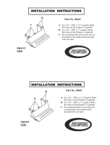
27) Install Overhead Limit Switch to the Overhead
Beam using the rear set of holes on the Power
Side of the lift. Fig. 7.
Fig. 7 – Overhead Limit Switch Power Side
28) Install the Idler Bracket to the Overhead Beam
using the rear set of holes on the Idler Side of
the lift. Fig. 8. Note the orientation of the Idler
Bracket. The narrow slot needs to be facing
towards the Power Column. Slide the Shutoff
Bar over the limit switch on the Power Side. Pin
the Shutoff Bar to the Idler Side Bracket with the
10mm dia. x 55mm Lg. clevis pin & hairpin
cotter.
Fig. 8 – Overhead Bracket Idler Side
SYNCHRONIZER CABLES
29) Remove Cable Trapping Hardware at the top of
each column. Fig 9. Route free end of cables
coming out the top of the carriage up and over
the upper sheaves and back down the opposite
side. Do this for both cables and install the cable
trapping hardware.
Fig. 9 – Cable Trapping

Model CL16
Installation, Operation and Maintenance
Page 8
Rev. 08/24/2021
CL16-IOM-A.doc
STANDARD
6" REDUCED (-6")
12" REDUCED (-12")
STANDARD
6" REDUCED (-6")
12" REDUCED (-12")
STANDARD
6" REDUCED (-6")
12" REDUCED (-12")
STANDARD
6" REDUCED (-6")
12" REDUCED (-12")
Fig. 10 – Cable Attachment At The Carriage
30) Mount synchronizer cables to carriages as
shown in Fig. 10. Note: Use the proper Take-
Up Tube as shown in Fig 10 based on the
width of the lift.
HYDRAULICS
IMPORTANT: To ensure proper hose fitting seal
without damage to the fitting follow this
procedure for each hose connection: Screw flared
fitting on finger tight. Rotate flared fitting 1 1/2 hex
flats (90 deg.). Back the flared fitting off one full turn.
Again tighten flared fitting finger tight, then rotate
flared fitting 1 1/2 hex flats (90 deg.).
31) Mount Power Unit to power column as shown in
Fig 11. The mounting hardware, (4) 5/16”-18NC
hex nuts, are pre-installed on power unit
mounting bracket.
Fig. 11 – Power Unit Mounting
32) Install 9/16”-18 O-ring elbow (in hardware box) into
power unit, Fig. 11. CAUTION do not damage
rubber O-ring.
33) Install the block hose clamp bracket onto both
column extensions using 1/4”-20NC x 3/4” lg.
hex flange bolt and nut, see Fig 12.

Model CL16
Installation, Operation and Maintenance
Page 9
Rev. 08/24/2021
CL16-IOM-A.doc
IDLER SIDE POWER SIDE
BLOCK
HOSE
BRACKET
OVERHEAD
HOSE
IDLER
SIDE
HOSE
POWER
SIDE
HOSE
BLOCK
CLAMP
IDLER SIDE POWER SIDE
BLOCK
HOSE
BRACKET
OVERHEAD
HOSE
IDLER
SIDE
HOSE
POWER
SIDE
HOSE
BLOCK
CLAMP
IDLER SIDE POWER SIDE
BLOCK
HOSE
BRACKET
OVERHEAD
HOSE
IDLER
SIDE
HOSE
POWER
SIDE
HOSE
BLOCK
CLAMP
IDLER SIDE POWER SIDE
BLOCK
HOSE
BRACKET
OVERHEAD
HOSE
IDLER
SIDE
HOSE
POWER
SIDE
HOSE
BLOCK
CLAMP
Fig. 12 – Hose Mounting
34) Uncoil the Idler Side hose and Overhead hose
and attach them together. Route the loose end
through Idler Side column extension as shown in
Fig 12.
35) Assemble the block clamp (from hardware box)
around the overhead hose, lift the hose
assembly to remove the slack, and tighten the
clamp.
36) Clamp the overhead hose at the idler end of the
overhead beam and hold a smooth radius in the
hose. (Each hose clamp requires one 3/8”-16NC
x 3/4” lg. hex flange bolt and one hex flange nut).
Route hose across overhead to the other side.
Clamps are not needed yet
37) Uncoil Power Side hose and loosely attach it to
the Hydraulic tee fitting (in hardware box).
38) Bring the Power Unit Hose and Power Side Hose
up the column to the lowest available hole of the
column extension. Insert steel tubing end of the
Power Unit Hose into the extension (outside in)
and connect to the tee. Leave the assembly
hanging.
39) Install a steel line clamp and hose clamp on the
outside of the power column extension to secure
the power unit hose, as shown in Fig 13. (Use
1/4”-20NC x 3/4” lg. hex flange bolt, Spacer, and
hex flange nut for steel line clamp. The Spacer
goes between the Power Side Column Extension
and Line Clamp.) Note: The steel line inside
the column should be horizontal.
Fig. 13-Power Unit Hose Clamps

Model CL16
Installation, Operation and Maintenance
Page 10
Rev. 08/24/2021
CL16-IOM-A.doc
40) If installing a CL16-0, use the Routing Diagram C
in Fig 14. If installing a CL16-2 use the table in
Fig 14 to determine the proper routing diagram
A, B, OR C.
CL16-2 Standard Width and Height
CL16-2 6" Reduced Height without Reduced Width
CL16-2 6" or 12" Reduced Width without Reduced Height
CL16-2 6" Reduced Height with 6" or 12" Reduced Width
CL16-2 12" Reduced Height
CL16-0 ALL Widths and Heights
CL16-2 HEIGHT
CL16-2 WIDTH
STD -6" -12"
STD
-6"
-12"
AB
C
BC
A
HOSE ROUTING TABLE
HOSE ROUTING DIAGRAMS
B
BC
CCC
Fig. 14 – Overhead Hose Routing Diagram
41) Route the overhead hose based on the lifts
height and width. To make a loop, twist the hose.
Loosely connect the overhead hose to the other
end of the tee.
42) Tighten the three hose fitting connections at the
Tee taking care not to twist or change the lay of
any hose. Install and tighten the block clamp on
the power side to hold up the connect to the tee,
see Fig 12.
43) Install a Hose Clamp at the power end of the
overhead beam to hold a smooth radius in the
hose.
44) Install the rest of the overhead hose clamps as
shown in Fig 14 depending on the lift
configuration.
45) Each column hose should connect to its cylinder
with a 90 degree elbow rotated up from
horizontal and be routed thru the Hose Guide
Tabs as shown in Fig. 15.
46) Slightly loosen the 90 Degree Fitting jam nut at
the bottom of the Power Side Cylinder. Rotate
fitting to remove the slack from the power side
hose and tighten jam nut. Note: This is not
necessary for the Idler side.
Fig. 15-Hose Connection
47) BE CERTAIN ALL FITTINGS AND CONNECTIONS ARE
TIGHT. IT IS THE INSTALLER’S RESPONSIBILITY TO
ENSURE SYSTEM IS LEAK-FREE. Fill the Power Unit
with three gallons of clean 10wt anti-foam anti-
rust hydraulic oil or Dexron III ATF. DO NOT USE
OILS WITH DETERGENTS.

Model CL16
Installation, Operation and Maintenance
Page 11
Rev. 08/24/2021
CL16-IOM-A.doc
LOCK RELEASE
48) Assemble the fittings to the air valve, Fig. 16,
with the barbed fitting (3/8” hose barb x 1/8NPT)
in port marked “1”, the elbow (1/8” push-lock x
1/8NPT) in port “2”, and nothing in the center
port “3” (exhaust). Note: Barbed fitting in port
marked “1” may be substituted with 1/8” NPT
fitting suitable for the chosen compressed air
supply method.
49) Attach the valve to the Power Unit Bracket using
two #8-32 x 1 1/4” Lg. Pan Head Screws.
50) Cut a piece of the 1/8” O.D. air line 9" long and
use it to connect the bottom of the Tee fitting to
the elbow, Fig. 16.
Fig. 16 – Cable Assembly
51) Cut to fit a piece of the 1/8” O.D. air line and use
it to connect from the lock release air cylinder to
the center of the push-lock tee fitting on the
Power Column, Fig 16.
52) Connect the rest of the 1/8” air line to the top of
the tee and run it along side the hydraulic hose
up the column and across the overhead
attaching it to the hydraulic hose with wire ties
(Fig 17).
53) At the Idler side feed the air line thru the lowest
large opening in the column extension and down
the column.
54) Secure the air line to the Idler Column using
black wire ties through the double holes in the
middle of the column. Place the head of the wire
tires inside the column. Cut the air line to length
and attach it to the idler side lock release air
cylinder (Fig. 17).
WIRE
TIE
WITH
HEAD
INSIDE
COLUMN
1
8" AIR
LINE
UNION
TEE
1/8" AIR
LINE
WIRE TIE
WIRE TIE WIRE
TIE
WITH
HEAD
INSIDE
COLUMN
WIRE
TIE
WITH
HEAD
INSIDE
COLUMN
1
8" AIR
LINE
UNION
TEE
1/8" AIR
LINE
WIRE TIE
WIRE TIE WIRE
TIE
WITH
HEAD
INSIDE
COLUMN
WIRE
TIE
WITH
HEAD
INSIDE
COLUMN
1
8" AIR
LINE
UNION
TEE
1/8" AIR
LINE
WIRE TIE
WIRE TIE WIRE
TIE
WITH
HEAD
INSIDE
COLUMN
WIRE
TIE
WITH
HEAD
INSIDE
COLUMN
1
8" AIR
LINE
UNION
TEE
1/8" AIR
LINE
WIRE TIE
WIRE TIE WIRE
TIE
WITH
HEAD
INSIDE
COLUMN
Fig. 17 – Lock Release
55) Connect the air valve to the shop’s compressed
air source, (reference page 3 for Air
Requirements), and test the function of the lock
release system. Each Column Lock should move
freely. When the Air Cylinder is fully extended,
the Column Lock should rest firmly against the
back of the column.
56) Remove the two nuts securing the right side of
the power unit, install the valve cover with these
nuts, and secure the hose to the cover with black
wire ties, Fig. 18.
Fig. 18 – Cable Assembly
57) Assemble the palm button to the valve.

Model CL16
Installation, Operation and Maintenance
Page 12
Rev. 08/24/2021
CL16-IOM-A.doc
58) Install the Lock Release Covers on the Power
and Idler Columns.
ARM INSTALLATION
59) Lubricate the arm pin or carriage arm pin hole
with “anti-seize” and install the arms. Install the
Arm Pin Snap Ring.
60) Install the Arm Restraints with the 1/2”-13 Socket
Head Cap Screws. Ensure that the arm restraint
threads engage and disengage properly. Arm
restraints should disengage when lift is fully
lowered (Fig 19).
61) Extend the footpad to both extents and apply
“anti-seize” to the retaining ring.
Fig. 19 – Arm Installation
62) Make sure all the arm stop screws are tight.
Slide all the arms out so they are fully extended
making sure that the intermediate is retained in
the female and the male is retained in the
intermediate arm.
63) Locate the two pre-drilled holes on the back of
each column 19” up from the top of the base
plate. Center the adapter rack and attach with
5/16”-18NC x 1” Lg hex flange cap screw and
5/16” hex flange nut (Fig. 20).
Fig. 20 – Adapter Rack Installation
ELECTRICAL
See Figure 21 for the following steps.
64) Wire tie Limit Switch cord to Overhead hydraulic
Hose and Power Unit Hose.
65) Connect the Overhead Limit Switch Cord to
Power Unit
66) Connect Power Unit to suitable electrical source.
67) Energize the power unit and begin raising the
cylinder casings to reengage the carriage.
Note: The air in the cylinders and hoses must be
compressed before the cylinders will start to
move. Once the cylinders do begin to move, the
motion will be erratic.
68) Continue raising the cylinders until the top of the
Power Side cylinder contacts the top plate of the
carriage.
Do not place fingers inside the
carriage.
69) Use a socket and extension on the bleed screw
at the top of the cylinder to align the cylinder with
the hole in the top of the carriage.
70) Repeat the previous two steps for the Idler Side
cylinder.
71) Continue energizing power unit to fully reengage
the cylinders with the carriages.
72) IMPORTANT: TEST OPERATION OF OVERHEAD
LIMIT SWITCH. WHILE RAISING LIFT, OPERATE
OVERHEAD SHUTOFF BAR. POWER UNIT MOTOR
SHOULD STOP WHEN SHUTOFF BAR IS RAISED.
WARNING

Model CL16
Installation, Operation and Maintenance
Page 13
Rev. 08/24/2021
CL16-IOM-A.doc
FINAL ADJUSTMENTS
HYDRAULICS
73) Lower the lift to the floor and raise the lift
approximately one foot.
74) Start with Idler side first. Slowly and carefully
loosen the bleed plug on top of the cylinder just
enough to allow the entrapped air to escape.
Repeat for power side.
75) Raise lift 6 inches. Repeat the previous step until
no air comes out of cylinder.
76) Pressure test hydraulic system. Energize power
unit, raise lift to full rise and continue to run
motor for additional 10 seconds. (NOTE:
pressure relief will make a high pitch squeal
sound for these 10 seconds.) Check hydraulic
system for leaks.
77) Energize power unit again for 10 seconds. With
a clean rag, wipe down both cylinder rods. (The
cylinders are shipped with a small amount of
clear anti-corosive lubricant that will be forced
out through the wiper when the lift reaches full
rise.) If lubricant is not wiped clean from the
cylinder rod, the cylinder will apear to be
leaking.
SYNCHRONIZING CABLES
78) Raise lift and ensure carriages lower into same
lock position.
79) Adjust synchronizing cables so the tension is
equal in both cables and carriages are firmly
sitting on locks.
80) Cycle lift to ensure that locks operate
simultaneously. Adjust if necessary.
FINAL CHECKOUT PROCEDURE
81) Demonstrate the operation of the lift to the
owner/operator/employer using a typical vehicle
and review correct and safe lifting procedures
using the Lifting It Right booklet as a guide.
82) Return all provided literature (including this
manual) to the literature pack envelope and
deliver the envelope to the
owner/operator/employer.
83) Complete the online warranty registration (refer
to the included warranty statement).

Model CL16
Installation, Operation and Maintenance
Page 14
Rev. 08/24/2021
CL16-IOM-A.doc
A2A1
T9
T5
T4
T6
M
T8
T3
T7
T2
T1
12
34
56
L3
L2
L1
T3
T2
T1
FACTORY WIRED FOR
208−240V
6
4
2
5
3
1
RECONNECTIONS FOR
440−480V
T3
T2
T1
T9
T6
T7
T4
T8
T5
FOR THREE PHASE
M
Wiring Diagram
2/T11/L1
3/A14/A2
LOAD
INPUT
M
(Normally Open)
FIELD CONNECTIONS
FOR SINGLE PHASE
Fig 21 – Electrical Wiring Diagram

Model CL16
Installation, Operation and Maintenance
Page 15
Rev. 08/24/2021
CL16-IOM-A.doc
OPERATION PROCEDURE
SAFETY NOTICES AND DECALS
This product is furnished with graphic safety
warning labels, which are reproduced on
page 3 of these instructions. Do not remove
or deface these warning labels, or allow them
to be removed or defaced. For your safety,
and the safety of others, read and understand
all of the safety notices and decals included.
OWNER/EMPLOYER RESPONSIBILITIES
This lift has been designed and constructed according
to ANSI/ALI ALCTV standard. The standard applies to
lift manufactures, as well as to owners and employers.
The owner/employer’s responsibilities as prescribed by
ANSI/ALI ALOIM, are summarized below. For exact
wording refer to the actual standard provided with this
manual in the literature pack.
The Owner/Employer shall ensure that lift
operators are qualified and that they are trained
in the safe use and operation of the lift using the
manufacturer’s operating instructions; ALI/SM
93 -1, ALI Lifting it Right safety manual; ALI/ST-
90 ALI Safety Tips card; ANSI/ALI ALOIM,
American National Standard for Automotive Lifts-
Safety Requirements for Operation, Inspection
and Maintenance; ALI/WL Series, ALI Uniform
Warning Label Decals/Placards; and in case of
frame engaging lifts, ALI/LP-GUIDE, Vehicle
Lifting Points/Quick Reference Guide for Frame
Engaging Lifts.
The Owner/Employer shall establish
procedures to periodically inspect the lift in
accordance with the lift manufacturer’s
instructions or ANSI/ALI ALOIM, American
National Standard for Automotive Lifts-Safety
Requirements for Operation, Inspection and
Maintenance; and the employer shall ensure that
the lift inspectors are qualified and that they are
adequately trained in the inspection of the lift.
The Owner/Employer shall establish
procedures to periodically maintain the lift in
accordance with the lift manufacturer’s
instructions or ANSI/ALIOIM, American National
Standard for Automotive Lifts-Safety
Requirements for Operation, Inspection and
Maintenance; and the employer shall ensure that
the lift maintenance personnel are qualified and
that they are adequately trained in the
maintenance of the lift.
The Owner/Employer shall maintain the
periodic inspection and maintenance records
recommended by the manufacturer or ANSI/ALI
ALOIM, American National Standard for
Automotive Lifts-Safety Requirements for
Operation, Inspection and Maintenance.
The Owner/Employer shall display the lift
manufacturer’s operating instructions; ALI/SM
93 -1, ALI Lifting it Right safety manual; ALI/ST-
90 ALI Safety Tips card; ANSI/ALI ALOIM,
American National Standard for Automotive Lifts-
Safety Requirements for Operation, Inspection
and Maintenance; and in the case of frame
engaging lift, ALI/LP-GUIDE, Vehicle Lifting
Points/Quick Reference Guide for Frame
Engaging Lifts; in a conspicuous location in the
lift area convenient to the operator.
IMPORTANT SAFETY INSTRUCTIONS
When using your garage equipment, basic safety
precautions should always be followed, including
the following:
1. Read all instructions.
2. Care must be taken as burns can occur
from touching hot parts.
3. To reduce the risk of fire, do not operate
equipment in the vicinity of open containers
of flammable liquids (gasoline).
4. Keep hair, loose clothing, fingers, and all
parts of body away from moving parts.
5. Use only as described in this manual. Use
only manufacturer’s recommended
attachments.
6. ALWAYS WEAR SAFETY GLASSES.
Everyday eyeglasses only have impact
resistant lenses, they are not safety glasses.
SAVE THESE INSTRUCTIONS

Model CL16
Installation, Operation and Maintenance
Page 16
Rev. 08/24/2021
CL16-IOM-A.doc
LIFTING A VEHICLE
1) Ensure that the lifting arms are parked, out to full
drive thru position.
2) Center the vehicle between the columns (left to
right) in the service bay and position the vehicle’s
center of gravity at the midpoint between the
columns (fore and aft). NOTE: the center of
gravity is based on the weight distribution and is
not the same as the center point of the vehicle.
DO NOT EXCEED 4000 POUNDS PER ARM (16K).
DO NOT ATTEMPT TO LIFT THE VEHICLE WITH ONLY TWO
ARMS, AS THIS WILL VOID THE WARRANTY
ENSURE THAT THE HIGHEST POINT ON THE VEHICLE WILL
CONTACT THE OVERHEAD LIMIT SWITCH BAR.
DO NOT PLACE THE VEHICLE IN THE SERVICE BAY
BACKWARDS.
REFER TO THE VEHICLE MANUFACTURERS SERVICE
MANUAL, TECHNICAL BULLETINS, “VEHICLE LIFTING
POINTS GUIDE” (ALI/LP-GUIDE) OR OTHER
PUBLICATIONS TO LOCATE THE RECOMMENDED LIFTING
POINTS.
3) Position the arms and adapters so all four pads
contact the vehicle simultaneously.
The vehicle should remain level during lifting.
4) Raise the lift until all four wheels are off the
ground. Test the stability of the vehicle by
attempting to rock the vehicle. Check adapters for
secure contact with vehicle lift points. If the vehicle
seems unstable, lower the lift and readjust the
arms. If the vehicle is stable, raise the vehicle to a
height a few inches above the desired working
height.
5) Lower the vehicle until the safety locks on both
columns engage. The vehicle should remain level
when both locks are engaged. If one side
engages and the other continues to descend, stop
lowering the vehicle, raise it several inches, and
try again to engage both locks.
Always lower lift into locks before entering the
area beneath the vehicle.
Always use safety stands when removing or
installing heavy components.
LOWERING A VEHICLE
1) Ensure that the area under the vehicle is clear of
personnel and tools.
2) Raise the vehicle until both locks are free.
3) Disengage the locks by pressing and holding the
lock release palm button.
4) Lower the vehicle by depressing the lowering
valve handle.
5) Continue to lower the vehicle until the carriages
stop against the base plate. Retract the extension
arms, and park them.
LOSS OF POWER
If for any reason the lift will not raise off the locks or
the locks will not retract, consult factory authorized
personnel.
DO NOT OVERRIDE ANY SAFETY FEATURE IN AN
ATTEMPT TO LOWER THE LIFT.

Model CL16
Installation, Operation and Maintenance
Page 17
Rev. 08/24/2021
CL16-IOM-A.doc
MAINTENANCE
To avoid personal injury, permit only qualified
personnel to perform maintenance on this equipment.
Maintenance personnel should follow lockout/tagout
instructions per ANSI Z244.1.
The following maintenance points are suggested as
the basis of a routine maintenance program. The
actual maintenance program should be tailored to the
installation and include a record of each planned
maintenance activity and repair maintenance activity
performed. Refer to the maintenance section of the
ANSI/ALI ALOIM booklet (blue book) provided with
the lift.
If lift stops short of full rise or chatters, check fluid
level and bleed both cylinders per Installation
Instructions.
Replace all Safety, Warning or Caution Labels if
missing or damaged (See Installation
instructions page 3.)
Daily
Keep lift components clean.
Check for loose or broken parts.
Check hydraulic system for fluid leaks.
Check adapters for damage or excessive wear.
Replace as required with genuine Challenger Lifts
parts.
Check lock release activation. Each Column Lock
should move freely. When the Air Cylinder is fully
extended, the Column Lock should rest firmly
against the back of the column.
Weekly
Check synchronizer cables and sheaves for wear.
Replace as required with genuine Challenger Lifts
parts.
Check synchronizer cable tension per Installation
Instructions. Adjust if necessary. If both threaded
ends of either cable have run out of adjustment,
then replace both cables. (Cables should always be
replaced in sets.)
Monthly
Torque concrete anchor bolts to 80 ft-lbs.
Visually inspect concrete floor for cracks and/or
spalling within 12” of base plate
Check overhead shutoff switch. While raising lift,
operate overhead shutoff bar. Power Unit motor
should stop when bar is raised.
Lubricate carriage slide tracks with heavy viscous
grease. (Grease all (4) corners of both columns.)
If any problems are encountered, contact your
local service representative.

Model CL16
Installation, Operation and Maintenance
Page 18
Rev. 08/24/2021
CL16-IOM-A.doc

Model CL16
Installation, Operation and Maintenance
Page 19
Rev. 08/24/2021
CL16-IOM-A.doc
PARTS BREAKDOWN
Fig A. Column Extension & Overhead
ITEM # PART # QTY
DESCRIPTION
1
12321-P 1
POWER COLUMN WELD
12321-I IDLER COLUMN WELD
2
12312-0 2
COLUMN EXTENSION WELD (STD Height.)
12312-2 COLUMN EXTENSION WELD (2ft.)
3 12301 1
OVERHEAD
4 A2067 1
SHUTOFF BAR
5 31129 1
SHUTOFF BAR CUSHION
6 B2064-01 1
LIMIT SWITCH PACKAGE
(INCLUDES SWITCH w/ CORD, BOTH BRACKETS, & ITEMS 7-10)
7 B2065-3 4
M6 x 14mm PHILLIPS PAN HEAD SCREW
8 B2065-4 4
M6 SERRATED FLANGE HEX NUT
9 B2065-5 1
CLEVIS PIN 10mm x 55 Lg.
10 GJY12-3 1
HAIRPIN COTTER
11 12330 24
1/2-13NC HEX. FLG. HD. C.S x 1” Lg.
12 12331 24
1/2-13NC HEX. FLG. NUT
13 A1154 8
3/8”-16 HEX FLANGE NUT
14 A2159 4
3/8”-16NC x 3” Lg. HEX HEAD CAP SCREW
12310-0 1
COLUMN EXTENSION PACK (14’-6” O.A. Ht.) Items (2, 13, 14, 66, 67, 68, 69)
12310-2 COLUMN EXTENSION PACK (16’-6” O.A. Ht.) Items (2, 13, 14, 66, 67, 68, 69)
Replace all worn, damaged, or broken parts with parts approved by Challenger Lifts Inc.
or with parts meeting Challenger Lifts Inc. specifications.
Contact your local Challenger Lifts Parts Distributor for pricing and availability.
(Call Challenger Lifts Inc. (502) 625-0700 for the Parts Distributor in your area)

Model CL16
Installation, Operation and Maintenance
Page 20
Rev. 08/24/2021
CL16-IOM-A.doc
PARTS BREAKDOWN (continued)
Fig B. Lock-Power/Idler
/