Page is loading ...

USER MANUAL
Cat. No. N128-E1-01
K3HB-S/-X/-V/-H
Digital Indicators

I
Preface
Thank you for purchasing the K3HB.
This manual describes the functions, performance, and application methods
needed for optimum use of the K3HB.
Please observe the following items when using the K3HB.
•This product is designed for use by qualified personnel with a knowledge of
electrical systems.
•Read this manual carefully and make sure you understand it well to ensure that
you are using the K3HB correctly.
•Keep this manual in a safe location so that it is available for reference when
required.
Notice
(1) All rights reserved. No part of this manual may be reprinted or copied without the prior written permission of
OMRON.
(2) The specifications and other information contained in this manual are subject to change without notice in order
to make improvements.
(3) Every precaution has been taken in the preparation of this manual. Nevertheless, OMRON assumes no
responsibility for errors or omissions. If you discover any problems with this manual, please notify your nearest
OMRON representative, providing them with the catalog number provided on the cover.

II
Read and Understand this Manual
Please read and understand this manual before using the product. Please consult your OMRON
representative if you have any questions or comments.
Warranty and Limitations of Liability
WARRANTY
OMRON's exclusive warranty is that the products are free from defects in materials and workmanship
for a period of one year (or other period if specified) from date of sale by OMRON.
OMRON MAKES NO WARRANTY OR REPRESENTATION, EXPRESS OR IMPLIED, REGARDING
NON-INFRINGEMENT, MERCHANTABILITY, OR FITNESS FOR PARTICULAR PURPOSE OF THE
PRODUCTS. ANY BUYER OR USER ACKNOWLEDGES THAT THE BUYER OR USER ALONE HAS
DETERMINED THAT THE PRODUCTS WILL SUITABLY MEET THE REQUIREMENTS OF THEIR
INTENDED USE. OMRON DISCLAIMS ALL OTHER WARRANTIES, EXPRESS OR IMPLIED.
LIMITATIONS OF LIABILITY
OMRON SHALL NOT BE RESPONSIBLE FOR SPECIAL, INDIRECT, OR CONSEQUENTIAL
DAMAGES, LOSS OF PROFITS OR COMMERCIAL LOSS IN ANY WAY CONNECTED WITH THE
PRODUCTS, WHETHER SUCH CLAIM IS BASED ON CONTRACT, WARRANTY, NEGLIGENCE, OR
STRICT LIABILITY.
In no event shall the responsibility of OMRON for any act exceed the individual price of the product on
which liability is asserted.
IN NO EVENT SHALL OMRON BE RESPONSIBLE FOR WARRANTY, REPAIR, OR OTHER CLAIMS
REGARDING THE PRODUCTS UNLESS OMRON'S ANALYSIS CONFIRMS THAT THE PRODUCTS
WERE PROPERLY HANDLED, STORED, INSTALLED, AND MAINTAINED AND NOT SUBJECT TO
CONTAMINATION, ABUSE, MISUSE, OR INAPPROPRIATE MODIFICATION OR REPAIR.
Application Considerations
SUITABILITY FOR USE
OMRON shall not be responsible for conformity with any standards, codes, or regulations that apply to
the combination of products in the customer's application or use of the products.
At the customer's request, OMRON will provide applicable third party certification documents identifying
ratings and limitations of use that apply to the products. This information by itself is not sufficient for a
complete determination of the suitability of the products in combination with the end product, machine,
system, or other application or use.
The following are some examples of applications for which particular attention must be given. This is not
intended to be an exhaustive list of all possible uses of the products, nor is it intended to imply that the
uses listed may be suitable for the products.
•Outdoor use, uses involving potential chemical contamination or electrical interference, or conditions
or uses not described in this manual.
•Nuclear energy control systems, combustion systems, railroad systems, aviation systems, medical
equipment, amusement machines, vehicles, safety equipment, and installations subject to separate
industry or government regulations.
•Systems, machines, and equipment that could present a risk to life or property.
Please know and observe all prohibitions of use applicable to the products.
NEVER USE THE PRODUCTS FOR AN APPLICATION INVOLVING SERIOUS RISK TO LIFE OR
PROPERTY WITHOUT ENSURING THAT THE SYSTEM AS A WHOLE HAS BEEN DESIGNED TO
ADDRESS THE RISKS, AND THAT THE OMRON PRODUCTS ARE PROPERLY RATED AND
INSTALLED FOR THE INTENDED USE WITHIN THE OVERALL EQUIPMENT OR SYSTEM.
PROGRAMMABLE PRODUCTS
OMRON shall not be responsible for the user's programming of a programmable product, or any
consequence thereof.

III
Disclaimers
CHANGE IN SPECIFICATIONS
Product specifications and accessories may be changed at any time based on improvements and other
reasons.
It is our practice to change model numbers when published ratings or features are changed, or when
significant construction changes are made. However, some specifications of the products may be
changed without any notice. When in doubt, special model numbers may be assigned to fix or establish
key specifications for your application on your request. Please consult with your OMRON representative
at any time to confirm actual specifications of purchased products.
DIMENSIONS AND WEIGHTS
Dimensions and weights are nominal and are not to be used for manufacturing purposes, even when
tolerances are shown.
PERFORMANCE DATA
Performance data given in this manual is provided as a guide for the user in determining suitability and
does not constitute a warranty. It may represent the result of OMRON's test conditions, and the users
must correlate it to actual application requirements. Actual performance is subject to the OMRON
Warranty and Limitations of Liability.
ERRORS AND OMISSIONS
The information in this document has been carefully checked and is believed to be accurate; however,
no responsibility is assumed for clerical, typographical, or proofreading errors, or omissions.

IV
●Definition of Precautionary Information
The following notation is used in this manual to provide precautions required to
ensure safe usage of the product.
The safety precautions that are provided are extremely important to safety. Always
read and heed the information provided in all safety precautions.
The following notation is used.
●Symbols
Safety Precautions
WARNING
Indicates a potentially hazardous situation which, if not
avoided, will result in minor or moderate injury, or may result
in serious injury or death. Additionally there may be
significant property damage.
CAUTION
Indicates a potentially hazardous situation which, if not
avoided, may result in minor or moderate injury or in property
damage.
Symbol Meaning
Caution
General Caution
Indicates non-specific general cautions, warnings,
and dangers.
Electrical Shock Caution
Indicates possibility of electric shock under specific
conditions.
Prohibition General Prohibition
Indicates non-specific general prohibitions.
Mandatory
Caution
General Caution
Indicates non-specific general cautions, warnings,
and dangers.

V
●Precautions
WARNING
Do not touch the terminals while power is being supplied. Doing
so may possibly result in electric shock. Make sure that the
terminal cover is installed before using the product.
Always provide protective circuits in the network. Without
protective circuits, malfunctions may possibly result in accidents
that cause serious injury or significant property damage.
Provide double or triple safety measures in external control
circuits, such as emergency stop circuits, interlock circuits, or limit
circuits, to ensure safety in the system if an abnormality occurs
due to malfunction of the product or another external factor
affecting the product's operation.
CAUTION
Do not allow pieces of metal, wire clippings, or fine metallic
shavings or filings from installation to enter the product. Doing so
may occasionally result in electric shock, fire, or malfunction.
Do not use the product in locations where flammable or explosive
gases are present. Doing so may occasionally result in minor or
moderate explosion, causing minor or moderate injury, or property
damage.
Do not attempt to disassemble, repair, or modify the product.
Doing so may occasionally result in minor or moderate injury due
to electric shock.
Do not use the equipment for measurements within Measurement
Categories III and IV for K3HB-X and II, III, and IV for K3HB-S,
K3HB-V, and K3HB-H (according to IEC61010-1). Doing so may
occasionally cause unexpected operation, resulting in minor or
moderate injury, or damage to the equipment. Use the equipment
for measurements only within the Measurement Category for
which the product is designed.
Perform correct setting of the product according to the application.
Failure to do so may occasionally cause unexpected operation,
resulting in minor or moderate injury, or damage to the equipment.
Ensure safety in the event of product failure by taking safety
measures, such as installing a separate monitoring system.
Product failure may occasionally prevent operation of comparative
outputs, resulting in damage to the connected facilities and
equipment.
Tighten the screws on the terminal block and the connector
locking screws securely using a tightening torque within the
following ranges. Loose screws may occasionally cause fire,
resulting in minor or moderate injury, or damage to the equipment.
Terminal block screws: 0.43 to 0.58 N·m
Connector locking screws: 0.18 to 0.22 N·m

VI
Make sure that the product will not be adversely affected if the
DeviceNet cycle time is lengthened as a result of changing the
program with online editing. Extending the cycle time may cause
unexpected operation, occasionally resulting in minor or moderate
injury, or damage to the equipment.
Before transferring programs to other nodes or changing I/O
memory of other nodes, check the nodes to confirm safety.
Changing the program or I/O memory of other nodes may
occasionally cause unexpected operation, resulting in minor or
moderate injury, or damage to the equipment.
CAUTION

VII
(1) Do not use the product in the following locations.
• Locations subject to direct radiant heat from heating equipment
• Locations where the product may come into contact with water or oil
• Locations subject to direct sunlight
• Locations where dust or corrosive gases (in particular, sulfuric or ammonia gas) are
present
• Locations subject to extreme temperature changes
• Locations where icing or condensation may occur
• Locations subject to excessive shocks or vibration
(2) Do not use the product in locations subject to temperatures or humidity levels outside
the specified ranges or in locations prone to condensation. If the product is installed in a
panel, ensure that the temperature around the product (not the temperature around the
panel) does not go outside the specified range.
(3) Provide sufficient space around the product for heat dissipation.
(4) Use and store the product within the specified temperature and humidity ranges. If
several products are mounted side-by-side or arranged in a vertical line, the heat
dissipation will cause the internal temperature of the products to rise, shortening the
service life. If necessary, cool the products using a fan or other cooling method.
(5) The service life of the output relays depends on the switching capacity and switching
conditions. Consider the actual application conditions and use the product within the
rated load and electrical service life. Using the product beyond its service life may result
in contact welding or burning.
(6) Install the product horizontally.
(7) Mount to a panel between 1 and 8-mm thick.
(8) Use the specified size of crimp terminals (M3, width: 5.8 mm max.) for wiring. To
connect bare wires, use AWG22 (cross section: 0.326 mm2) to AWG14 (cross section:
2.081 mm2) to wire the power supply terminals and AWG28 (cross section: 0.081 mm2)
to AWG16 (cross section: 1.309 mm2) for other terminals. (Length of exposed wire: 6 to
8 mm)
(9) In order to prevent inductive noise, wire the lines connected to the product separately
from power lines carrying high voltages or currents. Do not wire in parallel with or in the
same cable as power lines. Other measures for reducing noise include running lines
along separate ducts and using shield lines.
(10) Ensure that the rated voltage is achieved no longer than 2 s after turning the power ON.
(11) Allow the product to operate without load for at least 15 minutes after the power is
turned ON.
(12) Do not install the product near devices generating strong high-frequency waves or
surges. When using a noise filter, check the voltage and current and install it as close to
the product as possible.
(13) Do not use thinner to clean the product. Use commercially available alcohol.
(14) Be sure to confirm the name and polarity for each terminal before wiring the terminal
block and connectors.
(15) Use the product within the noted supply volage and rated load.
Precautions for Safe Use

VIII
(16) Do not connect anything to unused terminals.
(17) Output turns OFF when the mode is changed or settings are initialized. Take this into
consideration when setting up the control system.
(18) Install an external switch or circuit breaker that complies with applicable IEC60947-1
and IEC60947-3 requirements and label them clearly so that the operator can quickly
turn OFF the power.
(19) Use the specified cables for the communications lines and stay within the specified
DeviceNet communications distances. Refer to the User's Manual (Cat. No. N129) for
details on communications distance specifications and cables.
(20) Do not pull the DeviceNet communications cables with excessive force or bend them
past their natural bending radius.
(21) Do not connect or remove connectors while the DeviceNet power is being supplied.
Doing so will cause product failure or malfunction.
(22) Use cables with a heat resistance of 70ºC min.

IX
●Noise Countermeasures
Do not install the product near devices generating strong high-frequency waves or
surges, such as high-frequency welding and sewing machines.
(1) Mount a surge suppressor or noise filter to peripheral devices generating noise, in
particular, motors, transformers, solenoids, and magnet coils.
(2) In order to prevent inductive noise, wire the lines connected to the terminal block
separately from power lines carrying high voltages or currents. Do not wire in parallel
with or in the same cable as power lines. Other measures for reducing noise include
running lines along separate ducts and using shield lines.
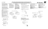
Example of Countermeasures for Inductive Noise on Input Lines
(3) If a noise filter is used for the power supply, check the voltage and current, and install
the noise filter as close to the product as possible.
(4) Reception interference may occur if the product is used close to a radio, television, or
wireless.
+
-
Power supply input
Power supply input
Signal input
Digital Indicator
Line filter
Surge suppressor
Digital
Indicator
+
-
Signal input
2 conductors with shield
Digital Indicator

Certain Terms and Conditions of Sale
1. Offer; Acceptance. These terms and conditions (these "Terms") are deemed
part of all catalogs, manuals or other documents, whether electronic or in writ-
ing, relating to the sale of goods or services (collectively, the "Goods") by
Omron Electronics LLC and its subsidiary companies ("Seller"). Seller hereby
objects to any terms or conditions proposed in Buyer's purchase order or other
documents which are inconsistent with, or in addition to, these Terms. Please
contact your Omron representative to confirm any additional terms for sales
from your Omron company.
2. Prices. All prices stated are current, subject to change without notice by
Seller. Buyer agrees to pay the price in effect at time of shipment.
3. Discounts. Cash discounts, if any, will apply only on the net amount of
invoices sent to Buyer after deducting transportation charges, taxes and
duties, and will be allowed only if (i) the invoice is paid according to Seller's
payment terms and (ii) Buyer has no past due amounts owing to Seller.
4. Orders. Seller will accept no order less than $200 net billing.
5. Governmental Approvals. Buyer shall be responsible for, and shall bear all
costs involved in, obtaining any government approvals required for the impor-
tation or sale of the Goods.
6. Taxes. All taxes, duties and other governmental charges (other than general
real property and income taxes), including any interest or penalties thereon,
imposed directly or indirectly on Seller or required to be collected directly or
indirectly by Seller for the manufacture, production, sale, delivery, importation,
consumption or use of the Goods sold hereunder (including customs duties
and sales, excise, use, turnover and license taxes) shall be charged to and
remitted by Buyer to Seller.
7. Financial. If the financial position of Buyer at any time becomes unsatisfactory
to Seller, Seller reserves the right to stop shipments or require satisfactory
security or payment in advance. If Buyer fails to make payment or otherwise
comply with these Terms or any related agreement, Seller may (without liability
and in addition to other remedies) cancel any unshipped portion of Goods sold
hereunder and stop any Goods in transit until Buyer pays all amounts, includ-
ing amounts payable hereunder, whether or not then due, which are owing to it
by Buyer. Buyer shall in any event remain liable for all unpaid accounts.
8. Cancellation; Etc. Orders are not subject to rescheduling or cancellation
unless Buyer indemnifies Seller fully against all costs or expenses arising in
connection therewith.
9. Force Majeure. Seller shall not be liable for any delay or failure in delivery
resulting from causes beyond its control, including earthquakes, fires, floods,
strikes or other labor disputes, shortage of labor or materials, accidents to
machinery, acts of sabotage, riots, delay in or lack of transportation or the
requirements of any government authority.
10. Shipping; Delivery. Unless otherwise expressly agreed in writing by Seller:
a. Shipments shall be by a carrier selected by Seller;
b. Such carrier shall act as the agent of Buyer and delivery to such carrier
shall constitute delivery to Buyer;
c. All sales and shipments of Goods shall be FOB shipping point (unless oth-
erwise stated in writing by Seller), at which point title to and all risk of loss of
the Goods shall pass from Seller to Buyer, provided that Seller shall retain a
security interest in the Goods until the full purchase price is paid by Buyer;
d. Delivery and shipping dates are estimates only.
e. Seller will package Goods as it deems proper for protection against normal
handling and extra charges apply to special conditions.
11. Claims. Any claim by Buyer against Seller for shortage or damage to the
Goods occurring before delivery to the carrier must be presented in writing to
Seller within 30 days of receipt of shipment and include the original transporta-
tion bill signed by the carrier noting that the carrier received the Goods from
Seller in the condition claimed.
12. Warranties. (a) Exclusive Warranty. Seller's exclusive warranty is that the
Goods will be free from defects in materials and workmanship for a period of
twelve months from the date of sale by Seller (or such other period expressed
in writing by Seller). Seller disclaims all other warranties, express or implied.
(b) Limitations. SELLER MAKES NO WARRANTY OR REPRESENTATION,
EXPRESS OR IMPLIED, ABOUT NON-INFRINGEMENT, MERCHANTABIL-
ITY OR FITNESS FOR A PARTICULAR PURPOSE OF THE GOODS.
BUYER ACKNOWLEDGES THAT IT ALONE HAS DETERMINED THAT THE
GOODS WILL SUITABLY MEET THE REQUIREMENTS OF THEIR
INTENDED USE. Seller further disclaims all warranties and responsibility of
any type for claims or expenses based on infringement by the Goods or other-
wise of any intellectual property right. (c) Buyer Remedy. Seller's sole obliga-
tion hereunder shall be to replace (in the form originally shipped with Buyer
responsible for labor charges for removal or replacement thereof) the non-
complying Good or, at Seller's election, to repay or credit Buyer an amount
equal to the purchase price of the Good; provided that in no event shall Seller
be responsible for warranty, repair, indemnity or any other claims or expenses
regarding the Goods unless Seller's analysis confirms that the Goods were
properly handled, stored, installed and maintained and not subject to contami-
nation, abuse, misuse or inappropriate modification. Return of any goods by
Buyer must be approved in writing by Seller before shipment. Seller shall not
be liable for the suitability or unsuitability or the results from the use of Goods
in combination with any electrical or electronic components, circuits, system
assemblies or any other materials or substances or environments. Any
advice, recommendations or information given orally or in writing, are not to be
construed as an amendment or addition to the above warranty.
13. Damage Limits; Etc. SELLER SHALL NOT BE LIABLE FOR SPECIAL, INDI-
RECT OR CONSEQUENTIAL DAMAGES, LOSS OF PROFITS OR PRODUC-
TION OR COMMERCIAL LOSS IN ANY WAY CONNECTED WITH THE
GOODS, WHETHER SUCH CLAIM IS BASED IN CONTRACT, WARRANTY,
NEGLIGENCE OR STRICT LIABILITY. Further, in no event shall liability of
Seller exceed the individual price of the Good on which liability is asserted.
14. Indemnities. Buyer shall indemnify and hold harmless Seller, its affiliates and
its employees from and against all liabilities, losses, claims, costs and
expenses (including attorney's fees and expenses) related to any claim, inves-
tigation, litigation or proceeding (whether or not Seller is a party) which arises
or is alleged to arise from Buyer's acts or omissions under these Terms or in
any way with respect to the Goods. Without limiting the foregoing, Buyer (at
its own expense) shall indemnify and hold harmless Seller and defend or settle
any action brought against Seller to the extent that it is based on a claim that
any Good made to Buyer specifications infringed intellectual property rights of
another party.
15. Property; Confidentiality. The intellectual property embodied in the Goods is
the exclusive property of Seller and its affiliates and Buyer shall not attempt to
duplicate it in any way without the written permission of Seller. Notwithstand-
ing any charges to Buyer for engineering or tooling, all engineering and tooling
shall remain the exclusive property of Seller. All information and materials
supplied by Seller to Buyer relating to the Goods are confidential and propri-
etary, and Buyer shall limit distribution thereof to its trusted employees and
strictly prevent disclosure to any third party.
16. Miscellaneous. (a) Waiver. No failure or delay by Seller in exercising any right
and no course of dealing between Buyer and Seller shall operate as a waiver
of rights by Seller. (b) Assignment. Buyer may not assign its rights hereunder
without Seller's written consent. (c) Amendment. These Terms constitute the
entire agreement between Buyer and Seller relating to the Goods, and no pro-
vision may be changed or waived unless in writing signed by the parties.
(d) Severability. If any provision hereof is rendered ineffective or invalid, such
provision shall not invalidate any other provision. (e) Setoff. Buyer shall have
no right to set off any amounts against the amount owing in respect of this
invoice. (f) As used herein, "including" means "including without limitation".
Certain Precautions on Specifications and Use
1
. Suitability of Use. Seller shall not be responsible for conformity with any stan-
dards, codes or regulations which apply to the combination of the Good in the
Buyer's application or use of the Good. At Buyer's request, Seller will provide
applicable third party certification documents identifying ratings and limitations
of use which apply to the Good. This information by itself is not sufficient for a
complete determination of the suitability of the Good in combination with the
end product, machine, system, or other application or use. The following are
some examples of applications for which particular attention must be given.
This is not intended to be an exhaustive list of all possible uses of this Good,
nor is it intended to imply that the uses listed may be suitable for this Good:
(i) Outdoor use, uses involving potential chemical contamination or electrical
interference, or conditions or uses not described in this document.
(ii) Energy control systems, combustion systems, railroad systems, aviation
systems, medical equipment, amusement machines, vehicles, safety
equipment, and installations subject to separate industry or government
regulations.
(iii) Systems, machines and equipment that could present a risk to life or
property. Please know and observe all prohibitions of use applicable to
this Good.
NEVER USE THE PRODUCT FOR AN APPLICATION INVOLVING SERIOUS
RISK TO LIFE OR PROPERTY WITHOUT ENSURING THAT THE SYSTEM
AS A WHOLE HAS BEEN DESIGNED TO ADDRESS THE RISKS, AND THAT
THE SELLER'S PRODUCT IS PROPERLY RATED AND INSTALLED FOR
THE INTENDED USE WITHIN THE OVERALL EQUIPMENT OR SYSTEM.
2. Programmable Products. Seller shall not be responsible for the user's pro-
gramming of a programmable Good, or any consequence thereof.
3. Performance Data. Performance data given in this catalog is provided as a
guide for the user in determining suitability and does not constitute a warranty.
It may represent the result of Seller's test conditions, and the user must corre-
late it to actual application requirements. Actual performance is subject to the
Seller's Warranty and Limitations of Liability.
4. Change in Specifications. Product specifications and accessories may be
changed at any time based on improvements and other reasons. It is our prac-
tice to change part numbers when published ratings or features are changed,
or when significant construction changes are made. However, some specifica-
tions of the Good may be changed without any notice. When in doubt, special
part numbers may be assigned to fix or establish key specifications for your
application. Please consult with your Seller's representative at any time to con-
firm actual specifications of purchased Good.
5. Errors and Omissions. The information in this catalog has been carefully
checked and is believed to be accurate; however, no responsibility is assumed
for clerical, typographical or proofreading errors, or omissions.

XI
About this Manual
Manual Structure
Preface
Provides precautionary information, a manual revision history, an
overview of the manual contents, information on using this manual,
and other general information.
Section 1 Outline
Provides an overview and describes the features of the product.
Section 2 Preparations
Describes the mounting and wiring required before using the product.
Section 3 Basic Application Methods
Shows typical applications for the product. Also shows wiring and
parameter settings which enables the user to understand how to use
the product from practical examples.
Section 4 Initial Setup
Describes the initial setup process when using this product.
Section 5 Functions and Operations
Describes the functions and settings methods for more effective use of
functions, displays, outputs, and settings for each application.
Section 6 User Calibration
Describes the methods for user calibration.
Section 7 Troubleshooting
Describes how to check and possible countermeasures for errors.
Appendices
Provides specifications and settings lists.

XII
●Settings Data Notation
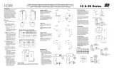
The letters of the alphabet in settings data are displayed as shown below.
●Applicable Model Notation
The following symbols are used to indicate the applicable models for specific
functions.
abcdefghijklm
ABCDEFGHI J KL M
nopqrstuvwxyz
NOPQRSTUVWXYZ
X
V
S
H
K3HB-X@@
K3HB-V@@
K3HB-H@@
K3HB-S@@

Contents
Contents
CONTENTS-1
CONTENTS
Section 1 Outline
1.1 Main Functions and Features of the K3HB . . . . . . . . . . . . . . . . . . . . . . . . . . . . . . . . . . . . 1-2
1.2 Component Names and Functions . . . . . . . . . . . . . . . . . . . . . . . . . . . . . . . . . . . . . . . . . . . 1-5
1.3 Internal Block Diagram. . . . . . . . . . . . . . . . . . . . . . . . . . . . . . . . . . . . . . . . . . . . . . . . . . . . 1-6
Section 2 Preparations
2.1 Mounting. . . . . . . . . . . . . . . . . . . . . . . . . . . . . . . . . . . . . . . . . . . . . . . . . . . . . . . . . . . . . . . 2-2
2.2 Using I/O. . . . . . . . . . . . . . . . . . . . . . . . . . . . . . . . . . . . . . . . . . . . . . . . . . . . . . . . . . . . . . . 2-4
Section 3 Basic Application Methods
3.1 Monitoring Tank Levels . . . . . . . . . . . . . . . . . . . . . . . . . . . . . . . . . . . . . . . . . . . . . . . . . . . 3-2
3.2 Monitoring Motor Load Current. . . . . . . . . . . . . . . . . . . . . . . . . . . . . . . . . . . . . . . . . . . . . 3-6
3.3 Weighing Material. . . . . . . . . . . . . . . . . . . . . . . . . . . . . . . . . . . . . . . . . . . . . . . . . . . . . . . . 3-9
3.4 Temperature Monitoring/Control with Multi-level Output. . . . . . . . . . . . . . . . . . . . . . . . . 3-11
3.5 Product Height Measurement and OK/NG Judgement. . . . . . . . . . . . . . . . . . . . . . . . . . . . 3-14
3.6 Panel Thickness Inspection. . . . . . . . . . . . . . . . . . . . . . . . . . . . . . . . . . . . . . . . . . . . . . . . . 3-17
3.7 Measurement of Disk Eccentricity . . . . . . . . . . . . . . . . . . . . . . . . . . . . . . . . . . . . . . . . . . . 3-20
3.8 Step Inspection . . . . . . . . . . . . . . . . . . . . . . . . . . . . . . . . . . . . . . . . . . . . . . . . . . . . . . . . . . 3-22
Section 4 Initial Setup
4.1 K3HB-X Initial Setup Example (K3HB-XVD) . . . . . . . . . . . . . . . . . . . . . . . . . . . . . . . . . 4-2
4.2 K3HB-V Initial Setup Example (K3HB-VLC). . . . . . . . . . . . . . . . . . . . . . . . . . . . . . . . . . 4-4
4.3 K3HB-H Initial Setup Example (K3HB-HTA). . . . . . . . . . . . . . . . . . . . . . . . . . . . . . . . . . 4-6
4.4 K3HB-S Initial Setup Example (K3HB-SSD) . . . . . . . . . . . . . . . . . . . . . . . . . . . . . . . . . . 4-8
Section 5 Functions and Operations
Section 5Knowledge Required for Setting Parameters. . . . . . . . . . . . . . . . . . . . . . . . . . . . . . . . . 5-2
-----Operation Adjustments ------------------------------------------------------------------------------
5.1 Setting Calculations . . . . . . . . . . . . . . . . . . . . . . . . . . . . . . . . . . . . . . . . . . . . . . . . . . . . . . 5-9
5.2 Setting Input Types . . . . . . . . . . . . . . . . . . . . . . . . . . . . . . . . . . . . . . . . . . . . . . . . . . . . . . . 5-11
5.3 Setting Scaling Values. . . . . . . . . . . . . . . . . . . . . . . . . . . . . . . . . . . . . . . . . . . . . . . . . . . . . 5-14
5.4 Setting the Temperature Unit . . . . . . . . . . . . . . . . . . . . . . . . . . . . . . . . . . . . . . . . . . . . . . . 5-18
5.5 Setting Measurement Operations . . . . . . . . . . . . . . . . . . . . . . . . . . . . . . . . . . . . . . . . . . . . 5-19
5.6 Shifting the Temperature Input . . . . . . . . . . . . . . . . . . . . . . . . . . . . . . . . . . . . . . . . . . . . . . 5-24
5.7 Resetting Measurements . . . . . . . . . . . . . . . . . . . . . . . . . . . . . . . . . . . . . . . . . . . . . . . . . . . 5-26
5.8 Not Performing Measurements for Set Intervals . . . . . . . . . . . . . . . . . . . . . . . . . . . . . . . . 5-27

Contents
Contents
CONTENTS-2
---- Input Adjustments ------------------------------------------------------------------------------------
5.9 Selecting Operations for Input Errors. . . . . . . . . . . . . . . . . . . . . . . . . . . . . . . . . . . . . . . . . . 5-29
5.10 Disabling Cold Junction Compensation . . . . . . . . . . . . . . . . . . . . . . . . . . . . . . . . . . . . . . . . 5-31
5.11 Adjusting Timing Inputs. . . . . . . . . . . . . . . . . . . . . . . . . . . . . . . . . . . . . . . . . . . . . . . . . . . . 5-33
5.12 Eliminating Drift Near “0” . . . . . . . . . . . . . . . . . . . . . . . . . . . . . . . . . . . . . . . . . . . . . . . . . .5-36
5.13 Averaging Inputs. . . . . . . . . . . . . . . . . . . . . . . . . . . . . . . . . . . . . . . . . . . . . . . . . . . . . . . . . . 5-38
5.14 Detecting Sudden Input Changes . . . . . . . . . . . . . . . . . . . . . . . . . . . . . . . . . . . . . . . . . . . . . 5-41
---- Output Adjustments ----------------------------------------------------------------------------------
5.15 Changing Comparative Output Patterns . . . . . . . . . . . . . . . . . . . . . . . . . . . . . . . . . . . . . . . . 5-44
5.16 Preventing Output Chattering . . . . . . . . . . . . . . . . . . . . . . . . . . . . . . . . . . . . . . . . . . . . . . . . 5-46
5.17 Outputting for a Set Interval. . . . . . . . . . . . . . . . . . . . . . . . . . . . . . . . . . . . . . . . . . . . . . . . . 5-49
5.18 Delaying Output OFF Timing . . . . . . . . . . . . . . . . . . . . . . . . . . . . . . . . . . . . . . . . . . . . . . . 5-52
5.19 Holding Measurement Status . . . . . . . . . . . . . . . . . . . . . . . . . . . . . . . . . . . . . . . . . . . . . . . . 5-54
5.20 Holding Comparative Outputs . . . . . . . . . . . . . . . . . . . . . . . . . . . . . . . . . . . . . . . . . . . . . . . 5-55
5.21 Allocating Another Output to PASS Output. . . . . . . . . . . . . . . . . . . . . . . . . . . . . . . . . . . . . 5-57
5.22 Reversing Output Logic . . . . . . . . . . . . . . . . . . . . . . . . . . . . . . . . . . . . . . . . . . . . . . . . . . . . 5-59
5.23 No Output before PASS Range. . . . . . . . . . . . . . . . . . . . . . . . . . . . . . . . . . . . . . . . . . . . . . . 5-61
5.24 Performing Linear Output . . . . . . . . . . . . . . . . . . . . . . . . . . . . . . . . . . . . . . . . . . . . . . . . . .5-63
---- Display Adjustments----------------------------------------------------------------------------------
5.25 Setting the Present Measurement Value to “0”. . . . . . . . . . . . . . . . . . . . . . . . . . . . . . . . . . . 5-65
5.26 Setting the Present Measurement Value to “0” Again when Using a Forced Zero . . . . . . . 5-67
5.27 Compensating Forced-zero References . . . . . . . . . . . . . . . . . . . . . . . . . . . . . . . . . . . . . . . . 5-70
5.28 Changing Display Refresh Periods. . . . . . . . . . . . . . . . . . . . . . . . . . . . . . . . . . . . . . . . . . . . 5-73
5.29 Holding Maximum and Minimum Values . . . . . . . . . . . . . . . . . . . . . . . . . . . . . . . . . . . . . . 5-75
5.30 Changing Normal Display Values to Maximum and Minimum Values . . . . . . . . . . . . . . . . 5-78
5.31 Setting the Step for Changing the Rightmost Digit . . . . . . . . . . . . . . . . . . . . . . . . . . . . . . . 5-80
5.32 Displaying/Not Displaying Comparative Set Values . . . . . . . . . . . . . . . . . . . . . . . . . . . . . . 5-82
5.33 Changing Display Colors . . . . . . . . . . . . . . . . . . . . . . . . . . . . . . . . . . . . . . . . . . . . . . . . . . .5-83
5.34 Using the Position Meter . . . . . . . . . . . . . . . . . . . . . . . . . . . . . . . . . . . . . . . . . . . . . . . . . . . 5-85
5.35 Automatic Return to Normal Display. . . . . . . . . . . . . . . . . . . . . . . . . . . . . . . . . . . . . . . . . . 5-88
5.36 No Decimal Point Display . . . . . . . . . . . . . . . . . . . . . . . . . . . . . . . . . . . . . . . . . . . . . . . . . .5-90
---- Other Operations--------------------------------------------------------------------------------------
5.37 Performing Output Tests. . . . . . . . . . . . . . . . . . . . . . . . . . . . . . . . . . . . . . . . . . . . . . . . . . . . 5-92
5.38 Using Comparative Set Value Banks . . . . . . . . . . . . . . . . . . . . . . . . . . . . . . . . . . . . . . . . . . 5-93
5.39 Copying Bank Comparative Set Values . . . . . . . . . . . . . . . . . . . . . . . . . . . . . . . . . . . . . . . . 5-98
5.40 Initializing All Settings. . . . . . . . . . . . . . . . . . . . . . . . . . . . . . . . . . . . . . . . . . . . . . . . . . . . . 5-100
5.41 Limiting Key Operations . . . . . . . . . . . . . . . . . . . . . . . . . . . . . . . . . . . . . . . . . . . . . . . . . . .5-102
Section 6 User Calibration
6.1 About User Calibration. . . . . . . . . . . . . . . . . . . . . . . . . . . . . . . . . . . . . . . . . . . . . . . . . . . . . 6-2
6.2 User Calibration Operation. . . . . . . . . . . . . . . . . . . . . . . . . . . . . . . . . . . . . . . . . . . . . . . . . .6-5

Contents
Contents
CONTENTS-3
Section 7 Troubleshooting
7.1 Error Displays . . . . . . . . . . . . . . . . . . . . . . . . . . . . . . . . . . . . . . . . . . . . . . . . . . . . . . . . . . . 7-2
7.2 Countermeasures. . . . . . . . . . . . . . . . . . . . . . . . . . . . . . . . . . . . . . . . . . . . . . . . . . . . . . . . . 7-3
Appendices
Specifications . . . . . . . . . . . . . . . . . . . . . . . . . . . . . . . . . . . . . . . . . . . . . . . . . . . . . . . . . . . . . . . . . A-2
Model Numbers. . . . . . . . . . . . . . . . . . . . . . . . . . . . . . . . . . . . . . . . . . . . . . . . . . . . . . . . . . . . . . . . A-9
Parameter List . . . . . . . . . . . . . . . . . . . . . . . . . . . . . . . . . . . . . . . . . . . . . . . . . . . . . . . . . . . . . . . . . A-12
Parameter Display Conditions . . . . . . . . . . . . . . . . . . . . . . . . . . . . . . . . . . . . . . . . . . . . . . . . . . . . A-17
About Parameters . . . . . . . . . . . . . . . . . . . . . . . . . . . . . . . . . . . . . . . . . . . . . . . . . . . . . . . . . . . . . . A-19
Sampling and Comparative Output Response Times . . . . . . . . . . . . . . . . . . . . . . . . . . . . . . . . . . . A-26
No Measurement Status . . . . . . . . . . . . . . . . . . . . . . . . . . . . . . . . . . . . . . . . . . . . . . . . . . . . . . . . . A-30

Contents
Contents
CONTENTS-4


Outline
Section 1 Outline
1-2
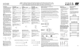
1.1 Main Functions and Features of the K3HB
Measurement
Filter
Input compensation
Input calculation Timing hold Timing delay
Two measurement values can
be added, subtracted, or the
ratio calculated. In addition,
any constant can be set and
measurement values can be
added to or subtracted from a
constant.
→ P. 5 - 9
Using external timing signal
inputs, synchronous
measurements can be made
and maximum values,
minimum values, and the
difference between maximum
and minimum values can be
measured.
→ P.5-18
The start and stop timing for
measurements can be
adjusted using timing signals.
→ P.5-33
Average processing Previous average value
comparison
Average processing of input
signals with extreme changes
or noise smooths out the
display and makes control
stable.
→ P.5-38
Slight changes can be
removed from input signals to
detect only extreme changes.
→ P.5-41
Forced-zero Tare zero Zero-trimming
Forces the present value to 0.
Effective to set a reference
value from which to perform
measurements.
→ P.5-65
Shifts the current value
measured with a forced zero
to 0 again.
Effective, for example, when
two compounds are measured
separately.
→ P.5-67
Compensates for gradual
changes in input signals from,
for example, sensor
temperature drift, based on
OK data (PASS data) at
measurement.
→ P.5-70
Zero-limit Step value Temperature input shift
Changes the display value to
0 for input values less than the
set value.
Effective when drift and
displacement of values near
zero need to be eliminated.
→ P.5-36
Sets the step size for
changing the value of the
rightmost digit of the
measurement value.
→ P.5-80
Shifts the temperature input
value.
→ P.5-24
S X V S H X V S H
X V S H X V S H
X V S X V S X V S
X V S X V S H H

Outline
1.1 Main Functions and Features of the K3HB
1-3
Key operations
Outputs
Teaching Key protection
During scaling, the input value
during measurement can be
set, as is, as the scaling input
value.
→ P.5-14
(Setting Scaling)
Limits key-operated level and
parameter changes to prevent
inadvertent key operations
and malfunctions.
→ P.5-102
Comparative output pattern Hysteresis Output refresh stop
The comparative output
pattern can be selected as
standard output, zone output,
and level output.
→ P.5-44
Prevents comparative output
chattering when the
measurement value fluctuates
slightly near the set value.
→ P.5-46
Holds the output status when
comparative results outputs
other than PASS turn ON.
→ P. 5 - 5 2
PASS output change Output OFF delay Shot output
Comparative results other
than PASS and error signals
can be output from the PASS
output terminal.
→ P.5-57
Connects the comparative output
OFF timing for a set interval.
Comparative output ON times can
be held when comparative results
change quickly.
→ P.5-55
Produces a constant
comparative output ON time.
→ P. 5 - 4 9
Output logic Startup compensation timer Output test
Reverses the output logic of
comparative outputs for
comparative results.
→ P.5-59
Constant-time measurements
can be stopped by an external
signal input.
→ P.5-27
Output operation can be
confirmed without actual input
signals, by setting test
measurement values using
the keys.
→ P. 5 - 9 0
Linear output Standby sequence
Outputs currents or voltages
proportional to measurement
values as they change.
→ P.5-65
Turns the comparative output
OFF until the measurement
value enters the PASS range.
→ P.5-61
X V S
X V S H X V S H X V S H
X V S H X V S H X V S H
X V S H X V S H X V S H
X V S H X V S H
/