Page is loading ...

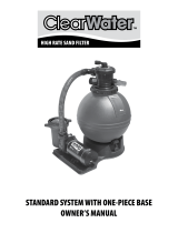
CARTRIDGE FILTER SYSTEM
OWNER’S MANUAL
Installation • Operation • Parts
810-0183-N.0618
©2018 Waterway Plastics
2200 East Sturgis Road, Oxnard CA 93030 • Phone 805.981.0262 • Fax 805.981.9403
www.waterwayplastics.com • waterway@waterwayplastics.com
Designed,
Engineered &
Manufactured
in the USA.

2
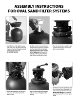
ASSEMBLY INSTRUCTIONS
FOR PROCLEAN PLUS FILTERS
Pre-assembled filter
Position of tube in body
Install pressure gauge following “Start/Service Dial Installation
Instructions” in separate bag inside fitting package.
Position of cartridge and tube
Tube
Cartridge
Body
Pressure
Gauge
Lid

3
ASSEMBLY INSTRUCTIONS
FOR FILTER SYSTEM WITH ONE-PIECE BASE
1. Put the base on level ground. Place pump on base. 2. Attach pump to base with included screw.
3. Place filter inside base. Wrap 3 or 4 turns of Teflon tape on 2" tailpiece
and thread into “inlet” in filter. DO NOT insert snap pins through
(secure) motor base until Step 3 is complete.
Teflon taped
2" tailpiece
threaded
into “inlet”

4
5. Wrap 3 or 4 turns of Teflon tape (provided) on 2" x 1 ½" MPT union
fitting and install into “outlet” of filter.
6. Place the other 1 ½" gasket in gate valve split-nut and thread onto
2"x 1 ½" MPT union fitting.
NOTE: Do not put Teflon tape on adapter threads to gate valve.
Place gasket
in split-nut
4. Make sure gasket is in place on elbow assembly and install
onto tailpiece. Elbow side has label “inlet.” Place gasket in pump
end of elbow assembly and attach to discharge on pump. Insert
snap pins through motor base and into filter base.
Gasket

5
READ AND FOLLOW SAFETY INSTRUCTIONS
This is the Safety Alert Symbol. When you see this
symbol on your filter or in this manual, look for one
of the following signal words and be alert to the potential for
personal injury!
warns about the hazard that will cause death,
serious injury or major property damage if ignored.
warns about hazards that can cause death,
serious injury or major property damage if ignored.
warns about hazards that can or will cause death,
serious injury or major property damage if ignored.
NOTICE: indicates special instructions not related to hazards.
Carefully read and follow all safety instructions in this manual
and on equipment. Keep safety labels in good condition; replace if
missing or damaged.
Hazardous Pressure. Incorrectly installed
or tested equipment may explode, causing severe injury or
property damage. Read and follow instructions in Owner’s Manual
when installing and operating equipment. Have a trained pool
professional perform all pressure tests.
Do not connect filter to compressed air under any
circumstances.
Do not connect system to a city water system or other external
source of pressurized water.
Do not connect filter to pumps capable of exceeding 50 PSI
(345 kPa) maximum pressure.
Open air release valve to vent all air from system before
operating the system.
Risk of falls and injury. Filter surface is slippery.
Do not allow children to stand or play on filter.
GENERAL INFORMATION
WHEN TO CLEAN THE FILTER:
The filter cartridge should normally be cleaned when the pressure
gauge reading increases 10 PSI over the start-up pressure.
In some pools, accessories such as fountains or pool cleaners may be
noticeably affected by the normal decrease in flow as the filter becomes
dirty. If so, clean the filter more frequently (that is, at a pressure
increase of less than 10 PSI) in order to maintain the required flow.
Clean a new pool as well as possible before filling pool and operating filter.
A typical pool installation will require approximately one week to obtain
and maintain the sparkle that your filter is capable of giving you.
Maximum pressure is 50 PSI (345 kPa). DO NOT connect the filter to a
city water system or to an individual water well system.
The Waterway Cartridge Filter is designed to filter water for swimming
pools and hot tubs only. On a new installation, we recommend:
1. Disassemble the filter after the initial cleanup. Follow
“Filter Disassembly/Assembly Procedure” on page 7.
2. Remove and hose down the cartridge to remove contaminant.
Maintain pool water pH between 7.2 and 7.6.
Make sure that the filter ring is securely locked in place before operating
filter.
Maintain the pressure gauge in good working order.
Replace a damaged gauge immediately.
Cleaning interval is based on pressure rise, not on the length of time the
filter is operated. Different water conditions will have different normal
cleaning intervals
NOTICE: Some pool disinfectants may clog the filter cartridge. To maximize
cartridge life and filter cycle time, closely follow the disinfectant
manufacturer’s instructions when cleaning pool or filter. Failure to follow
these instructions may affect warranty coverage of the cartridge.
OPERATING INSTRUCTIONS
WARRANTY
For product registration visit: www.waterwayplastics.com.
For Warranty questions or claims please contact point of purchase.

6
INSTALLATION
FILTER MOUNT MUST:
• Provide weather and freezing protection.
• Provide space and lighting for easy access for routine
maintenance.
• Provide ventilation and drainage for pump.
• Be on a reasonably level surface and provide adequate
drainage.
PIPING:
NOTICE: Make sure that the filter and all piping can be drained for
winterizing. See “Winterizing”, page 8.
NOTICE: Overtightening can crack filter ports.
Use Teflon tape, Plasto-Joint Stik®† or Silastic RTV #732® on all threaded
connections of plastic pipe and fittings.
DO NOT use pipe compounds on filter; it will cause the
connection to crack. Do not use sealant on unions; assemble
them dry and hand tight.
Support pipe independently to prevent strains on the filter.
Keep piping tight and free of leaks. Pump section line leaks may cause
trapped air in filter tank or loss of prime at pump.
† Lake Chemical Co., Chicago, Ill.
ELECTRICAL:
Be sure that pump grounding meets local and National Electrical Code
Standards. All wiring and grounding of associated equipment must
meet local and National Code Standards.
INITIAL START-UP
Be sure pump is OFF before starting procedure.
Do not operate filter at more than 50 PSI (345 kPa).
1. Securely lock the Pro-Clean Ring in place by rotating it CLOCKWISE
until it “clicks” past the safety latch (see Figure 3). Stop turning as
soon as the ring clicks past the latch. The ring may feel slightly
loose, but it will tighten up when the pump is on and the filter is
under pressure.
2. Install the pressure gauge and the air release valve (see Figure 2) on
the tank lid.
3. Fill the trap on the pump with water.
4. Open the air release valve on top of the filter.
5. Open valves separating the filter from the rest of the system.
6. Start the pump to purge air from the system.
7. When a steady stream of water comes from the air release valve,
close the valve.
NOTICE: Leaking around the filter ring may indicate that the ring is not
fully locked. In this case proceed as follows:
A. Stop the pump and open the air release valve then release
any pressure within the filter.
B. Remove the drain plug and drain all water from the filter.
C. Rotate the filter ring clockwise until it locks behind the
safety latch (see Figure 3).
D. If the ring was already locked, remove it and the filter lid
assembly. Inspect and clean the O-ring and all sealing surfaces.
Re-lubricate the O-ring, if necessary.
NOTICE: Lubricate the O-ring sealing area inside the upper tank lip
with silicone grease, as other lubricants may cause the ring to swell. DO
NOT lubricate the filter ring or the threads on the tank shell as this may
collect grit and make removal difficult.
Figure 2
Air Relief
Valve Pressure
Gauge
Filter Ring
Latch

7
FILTER DISASSEMBLY /
ASSEMBLY PROCEDURE
BEFORE DISASSEMBLING FILTER:
1. STOP PUMP.
2. OPEN air release valve and drain fitting.
3. WAIT until all pressure is released and water drained from
filter tank and system before loosening filter ring.
DISASSEMBLY:
1. Stop the pump.
2. Open air release valve on top of filter tank to release all pressure from
inside of tank.
3. Remove the drain cap and drain all water from the tank.
4. Remove filter lid assembly as follows:
A. Press the safety latch (below the ring) toward the tank to
release it (see Figure 3).
B. Hold the latch in the release position and rotate the ring
COUNTERCLOCKWISE to remove it. If the ring is difficult to turn,
tap it gently with a rubber mallet to overcome initial resistance.
5. Inspect the O-ring for cuts, cracking, deformation or signs of wear;
replace if necessary.
NOTICE: Do not remove the O-ring unless you need to replace it. To remove
it, hook it out of its groove with a stiff curved piece of wire inserted through
the small access slot in the bottom of the tank lid assembly.
ASSEMBLY:
1. Inspect and clean the tank, ring threads and O-ring groove. Replace
damaged parts as necessary.
2. Install the filter cartridge in the tank. Push down firmly to seal it.
NOTICE: Lubricate the O-ring sealing area inside the upper tank lip
Figure 3
with silicone base grease, as other lubricants may cause the ring to
swell. DO NOT lubricate the filter ring or the threads on the tank
shell as this may collect grit and make removal difficult.
3. Install the O-ring in the tank lid assembly O-ring groove. Be sure that
the O-ring is clean and not twisted.
NOTICE: Do not remove the O-ring unless you need to replace it.
4. Place the filter ring squarely over the tank shell threads and
rotate it CLOCKWISE until it is securely latched.
5. Follow instructions in the “Initial Startup” section of this manual.
SAFETY LATCH
The purpose of the safety latch is to hold the filter ring in the locked
position. If the latch is damaged, replace it as follows:
1. Press up on the small catch on the bottom of the safety
latch and press or tap the latch out of the slot in the tank.
2. Slide the new latch into position until it latches in place.
NOTICE: DO NOT operate the filter if the safety latch is damaged or will
not hold the filter ring in the locked position.
CARTRIDGE CLEANING PROCEDURE
WHEN TO CLEAN THE FILTER:
The filter cartridge should normally be removed and cleaned when the
pressure gauge reading increases 10 PSI over the start-up pressure.
Follow all steps in the “Disassembly” section of this manual (page 7).
NOTICE: When sanitizing your pool using PHMB (polyhexamethylene
biquanide) based cleaners, use ONLY PHMB cleaners to clean the
cartridge. When using PHMB sanitizers, the filter cartridge MUST be
cleaned more thoroughly and frequently than for a pool using chlorine.
Follow manufacturer’s instructions carefully. Use of any other type of
cleaners with PHMB pool sanitizers will void the filter’s warranty.
1. Remove the drain cap and flush all foreign material from the inside of
the tank before removing the filter cartridge.
2. Allow the tank to drain.
3. Lift out the cartridge and hose it down thoroughly. Spray the entire
cartridge surface. Allow cartridge to drain.
4. Inspect the cartridge. If necessary, repeat the washing operation. If
the cartridge is damaged, replace it.
5. Follow the steps in the “Assembly” (page 7) and “Initial Start-Up”
(page 6) sections of this manual.
NOTICE: When this procedure no longer adequately cleans the
cartridge, discard the cartridge and replace it with a new one.
Filter Ring

8
SYSTEM INSPECTION
GENERAL:
NOTICE: DO NOT use solvents to clean the filter. Solvents may damage
plastic components in the system.
NOTICE: Open the air release valve and bleed all air from the filter each
time the pump is stopped and restarted.
WEEKLY INSPECTION:
1. Remove debris from the pool skimmer basket.
2. Stop the pump; open the air release valve to release all pressure.
3. Remove the pump trap cover and basket; remove debris.
4. Check the pump for leaks. If found, see pump owner’s manual.
5. Replace the trap basket and the cover. Tighten the cover securely
hand tight. DO NOT use a lid wrench to tighten it.
6. Start the pump. When the filter air release valve runs a solid stream
of water, close the valve.
7. When the system has returned to normal operation, check the filter
pressure. If the filter pressure is 10 PSI (69 kPa) or more higher than
the initial start-up pressure, the filter needs cleaning. See “Cartridge
Cleaning Procedure” at left.
WINTERIZING
NOTICE: Protect the filter from freezing. Allowing the filter to freeze
will damage it and will void the warranty. If possible, take the system
indoors for storage.
1. Clean the filter according to instructions (left) before winterizing.
2. Stop the pump.
3. Open the air release valve; open any system valves.
4. Remove the drain plugs from the trap, pump and filter.
5. Gravity drain system and filter as far as possible.
6. Disassemble the filter (follow instructions under “Filter Disassembly”,
page 7). Remove the filter cartridge and store it in a warm, dry area.
7. Cover the filter with plastic or tarpaulin to prevent water entrance
and freezing.
TROUBLESHOOTING GUIDE
1. Short Cycle Time:
NOTICE: Cycle time will vary with each location and between different
areas of the country. The following causes and remedies are for cycle
times shorter than normal for your area.
A. Chlorine residual too low; maintain proper residual (consult pool
professional for recommendation).
B. Filter cartridge is dirty or plugged; thoroughly clean the filter (see no.
4, “Plugged Cartridge”, and “Cleaning Cartridge Procedure”, page 8).
C. Water is chemically out of balance; consult pool professional.
D. Algae in the pool; apply heavy dose of chlorine or algaecide as
recommended by the pool manufacturer.
E. Replace the cartridge.
2. Low Flow/High Pressure:
A. Cartridge plugged; clean filter thoroughly (see page 8).
B. Pipe blocked downstream from filter; remove obstruction.
C. Piping too small; use larger pipe (consult dealer for sizing).
3. Low Flow/Low Pressure:
A. Plugged pump or plugged debris basket; clean thoroughly.
4. Plugged Cartridge:
A. Insufficient cleaning; follow cleaning instructions closely and clean
thoroughly (see page 7).
B. Water chemically out of balance; consult pool professional.
C. Excessive air in filter; vent air from tank and check for pump
suction pipe leaks. Clean air bleed tube in cartridge assembly.
D. Pool water contains iron; consult your pool professional.
E. Heavy or improper application of powdered chlorine tablets using a
binder; consult your pool professional.
F. Algae in the pool; apply heavy dose of chlorine or algaecide as
recommended by the pool manufacturer.
G. Use of incorrect chemicals with PHMB sanitizers; replace filter cartridge.
H. Replace the cartridge.
5. Pool Water Not Clean:
A. Chlorine residual too low; maintain adequate chlorine residual
(consult pool service technician for recommendation).
B. Filter cartridge torn, plugged or punctured; replace cartridge.
C. Pool water contains iron; consult your pool professional.
D. Heavy or improper application of powdered chlorine tablets using a
binder; consult your pool professional.
E. Algae in the pool; apply heavy dose of chlorine or algaecide as
recommended by the pool manufacturer.
F. Replace the cartridge.
6. Pool Cleaner Stops Working:
A. Clean filter and observe performance of pool cleaner.
B. If pool cleaner performs better after filter has been cleaned, use a
shorter cleaning cycle for the filter (that is, clean the filter after a
pressure rise of less than 10 PSI).
/