Page is loading ...


NOTICE
This manual describes the CGW-T/TS/D Analog GSM/CDMA Cellular Gateway.
Additional copies of this manual may be obtained from ITS. No part of this document may be
reproduced or transmitted in any form, by any means (electronic, photocopying, recording, or
otherwise) without the prior written permission of ITS.
ITS reserves the right to modify the hardware and software described in the manual without
prior notice. However, changes made to the hardware or software described does not
necessarily render this publication invalid.
WARRANTY
In the event that the product proves to be defective in workmanship or materials within a
period of one year from date of shipment, ITS shall repair or replace the product at its
discretion. Transportation will be the responsibility of the dealer/distributor.
Under no circumstances shall ITS be liable for consequential or special damages, loss of
revenue or user/dealer expenses arising out of or in connection with the use or
performance of the product, whether based on contract, tort, or any other legal
agreement.
The following shall void the above warranty: malfunctions resulting from fire, accident,
neglect, abuse, or acts of God; use of improper electrical power; or repair of, tampering with
or alteration of the product by anyone other than ITS authorized personnel.

Table of Contents
1 Introduction............................................................................................... 1
1.1 Main Features .............................................................................................. 4
1.2 Contents ....................................................................................................... 5
2 Physical Description.................................................................................. 6
3 Pre-Installation.......................................................................................... 7
3.1 GSM Gateway ............................................................................................ 7
3.2 CDMA Gateway (CGW-T Only)................................................................. 7
4 Installation................................................................................................. 8
4.1 SIM Card Insertion into the Unit (GSM only)............................................. 8
4.2 CGW-T/TS/D Installation............................................................................ 9
5 LCD Status Indicators and Diagnostics ................................................ 12
5.1 CGW-T/D LCD Status Indicators and Diagnostics ................................... 12
5.2 CGW-TS LED Status Indicators and Diagnostics ..................................... 17
6 DTMF Programming.............................................................................. 22
7 Technical Data......................................................................................... 32
7.1 CGW-T/TS for GSM Network .................................................................. 32
7.2 CGW-T for CDMA Network..................................................................... 34
8 CGW-T/TS/D Accessories ...................................................................... 36

CGW-T/TS/D Installation and Programming Manual 1
1 Introduction
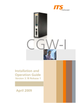
Your new CGW-T is an analog GSM/CDMA Cellular Gateway (CGW-TS/D – GSM only), a
cost reduction tool for mobile-to-landline and landline-to-mobile calls. It connects from the
trunk interface (analog FXO) of your PBX to a GSM network (via an inserted SIM card) or to
a CDMA network (by the built-in CDMA engine), eliminating the excessive interconnection
fees and significantly cutting your telephone costs.
The Automatic Route Select table (ARS) in the PBX defines which calls will be automatically
routed via the CGW-T to the predefined GSM/CDMA network. In doing so, the CGW-T/TS
gateway reduces the company’s telephone costs.
Installation of the CGW-T/TS/D does not require special skills. Simply insert the SIM card
(GSM networks only), connect the unit to the PBX trunk interface, attach the antenna and
power supply, and your CGW-T/TS/D can immediately start saving money for you. The unit
has an LCD display, which shows the GSM/CDMA operator’s name (CGW-T/D only), the
signal strength and other useful call progress information.
A number of additional parameters for the CGW-T/TS/D, such as Output Audio Volume level
setting, Conversation time-out and Restricted Digits, can be programmed via DTMF.
The CGW-T, CGW-TS and CGW-D units are displayed in Figure 1.


CGW-T/TS/D Installation and Programming Manual 3
Calls that are intended to be routed to the cellular network by the CGW-D, will be routed to
the PSTN network instead in the following cases:
A SIM card is not installed at all or not installed properly.
Cellular reception level is too low.
CGW-D device is in Registration mode.
CGW-D is not powered by the power supply.
NOTE
When the PSTN interface is plugged out, all calls shall be executed via a cellular
network, and a corresponding message will appear on the LCD display.
The Toll Restriction feature is implemented as follows:
CGW-T/TS devices use a black list of 10 restricted prefixes, which cannot be dialed.
CGW-D device uses a white list of 20 permitted prefixes, which are the only prefixes
that can be dialed via a cellular network.

4 CGW-T/TS/D Installation and Programming Manual
1.1 Main Features
The following list details the main features of the CGW-T/TS/D GSM/CDMA gateway:
Feature CGW-T CGW-TS CGW-D
Integrated dual-band GSM module (900/1800, 850/1900
MHz)
3 3 3
Integrated dual-band CDMA module (800/1900 MHz) 3
LED indicators 3
LCD indicators (signal strength, cellular operator name,
operational status)
3 3
DTMF programming: call barring (toll restriction),
conversation time-out, reverse polarity signaling support,
audio volume control, roaming control (GSM only), CLIR
(GSM only)
3 3 3
DTMF dialing 3 3 3
PSTN interface 3
Call forwarding
3
Line interface, 2-wire (RJ-11 connector) 3 3 3
Plug & Play installation 3 3 3
High voice quality 3 3 3
Maintenance free 3 3 3

CGW-T/TS/D Installation and Programming Manual 5
1.2 Contents
The contents of your CGW-T/TS/D package are as follows:
No. Item Qty.
1. CGW-T/TS/D device 1
2. Installation and Operation Manual 1
3. Power Supply
(Input: 110VAC, 60Hz or 220VAC, 50Hz)
(Output: 9VDC, 800mA)
1
4. Antenna (with cable) 1
5. RJ-11 telephone cable 1
6. Template for wall mounting 1
7. Screws and plugs for wall mounting 2

2 Physical Description
The physical features of the CGW-T/TS/D are detailed in Figure 2.
A
ntenna Connector
Signal Strength Indicator
PBX Trunk or Home Phone Connector
PSTN Interface (CGW-D only)
SIM Release Lever (GSM only)
SIM Card Tray (GSM only)
Power Supply Connector
LCD Display (for CGW-T/D) or
LED Display (for CGW-TS)
Figure 2. CGW-T/TS/D Physical Description
6 CGW-T/TS/D Installation and Programming Manual

CGW-T/TS/D Installation and Programming Manual 7
3 Pre-Installation
3.1 GSM Gateway
The CGW-T/TS/D unit contains a GSM engine. It therefore needs a SIM card from the local
GSM network provider. Its registration to the GSM operator is similar to that of a mobile
GSM phone.
The PIN and PUK code requests must be disabled (see LCD Messages table, below). If, for
any reason, you are unable to do so using an analog telephone connected to the
CGW-T/TS trunk socket, use any GSM mobile phone to modify the SIM card, or contact your
local GSM Service Center. CGW-D does not support PIN code-protected SIM cards.
CGW-D is able to recognize the disconnection of a circuit loop and a busy tone according to
the signaling received from the PSTN line.
3.2 CDMA Gateway (CGW-T Only)
The CGW-T (CDMA) contains a CDMA engine that needs to be activated via a local CDMA
network provider. You register the engine the way you would normally register a mobile
CDMA phone.
NOTE
It is recommended that you disable all call forwarding modes (in the events of busy,
absence, unavailability, etc.) and Call Waiting from the GSM/CDMA operator, before
installing the SIM card (GSM network), or activating the CDMA unit.

8 CGW-T/TS/D Installation and Programming Manual
4 Installation
4.1 SIM Card Insertion into the Unit (GSM only)
CAUTION
To avoid damage to the CGW-T/TS/D unit, disconnect the 9V adapter from the
electric power outlet.
The physical description of the unit can be used as guideline for the following steps:
Hold the unit in your hands with the display pointed to your left and the SIM insertion
slot at the bottom of the unit towards you (so that the text “SIM” is upside-down).
Using a screwdriver, push the yellow SIM release lever, so that the SIM card tray moves
towards you.
Take out the tray. You will see that the SIM card fits in the tray in one way only.
Carefully place the tray with the SIM card in the slot and slide it in with the SIM card
contacts facing down.

CGW-T/TS/D Installation and Programming Manual 9
4.2 CGW-T/TS/D Installation
To install the CGW-T/TS/D unit, perform the steps as follows:
Mount the CGW-T/TS/D unit on the wall as a stand-alone unit or on the 6-fold wall
mount bracket, which is a separate accessory.
Connect the antenna into the Ant. connector on the front panel of the CGW-T/TS/D unit.
Connect the analog trunk interface of the PBX to the Phone/PBX connector on the front
panel of the CGW-T/TS/D unit.
Connect the analog PSTN interface to the PSTN connector on the front panel of the
CGW-D unit (applicable to CGW-D only).
Connect the power supply to the CGW-T/TS/D unit. The unit will start the initialization
and registration. At the end of the process, the LCD will display the signal status
(CGW-T/D only).
NOTE
Adjust the antenna location until an optimal signal level is received.
Figure 3 displays the schematic setup of the CGW-T/TS unit. Figure 4 displays the schematic
setup of the CGW-D unit.


12 CGW-T/TS/D Installation and Programming Manual
5 LCD Status Indicators and Diagnostics
5.1 CGW-T/D LCD Status Indicators and Diagnostics
The CGW-T/D gateway can be connected to the analog trunk interface of the PBX. At power-
up of the CGW-T/D unit, the information on the LCD will provide the first diagnostics.
Usually, further diagnostics are unnecessary. By connecting an analog telephone with the RJ-
11 connector to the trunk (T) or Phone/PBX (D) connector in the unit, you are able to perform
further diagnostics.
5.1.1 LCD Status Indicators
The following table shows the messages appearing on the LCD, their description and the
action to be taken (if any).
LCD Message Description Action
Searching
Network…
Call forward to
PSTN (D only)
Searching for the mobile
network.
On D – call forwarded to
PSTN.
No action needed.
Incoming PSTN
Call (D only)
CGW-D gets call from PSTN
network
No action needed.
Incoming
Cellular Call (D
only)
CGW-D gets call from
PSTN network
No action needed

CGW-T/TS/D Installation and Programming Manual 13
LCD Message Description Action
Calling PSTN (D
only)
CGW-D dials to PSTN
destination
Wait
Calling Cellular
(D only)
CGW-D dials to PSTN
destination
Wait
Call forward (D
only)
Call forwarded with No
answer or Unconditional
mode
Wait
Enter PIN code
(T only, GSM
only)
PIN code is required to
activate the SIM card.
1. Connect an analog telephone to
the unit and enter the code. (4-8
digits. Add a # to the code when
using less than 8 digits)
2. Alternatively, insert the SIM
into your mobile phone and disable
the security option.
Registration…
Call FWD to
PSTN (D only)
Registration process after the
mobile network has been
found.
On D – call is forwarded to
PSTN line.
Wait till registration phase is
finished.
S=X dBm LCD shows signal level in
dBm.
If level is below 85 dBm, move the
antenna to another location with a
better reception.

14 CGW-T/TS/D Installation and Programming Manual
LCD Message Description Action
Name operator Name of Operator (read from
mobile network). No action needed.
Calling… CGW-T dials to destination. Wait.
Connected When called party answers. No action needed.
Disconnected End of call. No action needed.
Incoming Call CGW-T/D gets a call from
network. No action needed.
Failed
CGW-T/D receives incorrect
operation information from
the mobile network.
Try again.
Engine Problem
Call FWD to
PSTN
GSM/CDMA engine
problem.
On D – call is forwarded to
PSTN line.
Power the unit off and turn it on
again. If error is repeated, the unit
is faulty.
/