Page is loading ...


UK Combi-Tiller MK II 30/04-2019
2
Back to the table of contents
Content
*
EC-DECLARATION OF CONFORMITY ........................................................................................................... 3
DELIVERY CHECK ............................................................................................................................................... 4
MACHINE DESCRIPTION ................................................................................................................................... 4
RANGE OF APPLICATION ........................................................................................................................................ 4
TECHNICAL SPECIFICATIONS .................................................................................................................................. 4
SAFETY INSTRUCTIONS FOR COMBI-TILLER ............................................................................................ 5
SAFETY AND INSTRUCTIONS ON HYDRAULICS ........................................................................................ 6
INSTRUCTIONS ON TRANSPORT ON THE PUBLIC ROADS: ......................................................................................... 6
FRONT AXLE LOAD: ............................................................................................................................................... 6
LABELS ON THE MACHINE .............................................................................................................................. 7
EXPLANATION OF THE MACHINE LABELS .............................................................................................................. 7
START-UP OF THE MACHINE ........................................................................................................................... 8
GENERAL INFORMATION ........................................................................................................................................ 8
ATTACHMENT UND UNCOUPLING : ......................................................................................................................... 8
COMBI-TILLER - THREE-POINT MOUNTED MODELS. ............................................................................................... 8
COMBI-TILLER - COMBINED WITH TRAILED DISC-ROLLER..................................................................................... 8
SETTINGS AND ADJUSTMENT ......................................................................................................................... 8
STONE PROTECTION ............................................................................................................................................... 9
QUICK-PUSH SHEAR BOLT ..................................................................................................................................... 9
HYDRAULIC AUTOMATIC RELEASE SYSTEM ........................................................................................................... 10
REPLACEMENT OF WEARING POINT ........................................................................................................................ 11
MAINTENANCE ..................................................................................................................................................... 13
LUBRICATION ........................................................................................................................................................ 13
FRAME AND THREE-POINT LINKAGE, RIGID MODEL ............................................................................. 14
3.0 – 3.5 – 4.0 M ..................................................................................................................................................... 14
FRAME HYDRAULIC MODEL ........................................................................................................................... 15
4.0 – 5.0 M ............................................................................................................................................................. 15
SUPPORT WHEEL................................................................................................................................................. 16
DRAWBAR .............................................................................................................................................................. 17
WING SECTION ..................................................................................................................................................... 18
LINKAGE ................................................................................................................................................................ 19
CROSSBAR ............................................................................................................................................................. 20
TINE ......................................................................................................................................................................... 21
TINE TYPES ............................................................................................................................................................ 21
QUICK-PUSH TINES, SPARE PARTS UP TO MACHINE NO. : 200454 ........................................................................... 22
HYDRAULIC RELEASE SYSTEM, SPARE PARTS ......................................................................................................... 23
QUICK-PUSH TINES, SPARE PARTS FROM MACHINE NO. : 200455 ........................................................................... 24
HYDRAULICS ........................................................................................................................................................ 25
FOLDING CYLINDER ............................................................................................................................................... 25
DRAWBAR: ............................................................................................................................................................ 26
LINKAGE ................................................................................................................................................................ 27
HYDRAULICS FOR AUTOMATIC RELEASE SYSTEM (RIGID) ...................................................................................... 28
HYDRAULICS FOR AUTOMATIC RELEASE SYSTEM (HYDRAULIC) ............................................................................ 31
NOTES: .................................................................................................................................................................... 33

UK Combi-Tiller MK II 30/04-2019
3
Back to the table of contents
EC-DECLARATION OF CONFORMITY
in accordance with the EU Machinery Directive 2006/42/EC
applicable as from December 29th 2009:
HE-VA ApS
N. A. Christensensvej 34,
DK-7900 Nykøbing Mors
hereby confirms that the following machine has been manufactured in accordance with the Council
Directive 2006/42/EC.
The declaration comprises the following machine:
Combi-Tiller 3.0 – 3.5 – 4.0 m rigid
Combi-Tiller 4.0 – 5.0 m hydraulic
Nykøbing the 28th Februar 2011 Villy Christiansen
The undersigned is furthermore authorized to compile technical documentation for the above machine

UK Combi-Tiller MK II 30/04-2019
4
Back to the table of contents
Delivery check
Upon delivery to the dealer/supplier as well as to the customer, check the Combi-Tiller for possible
damages.
Machine description
Range of Application
Combi-Tiller is a sub-soiler developed for working solo or combined with a stubble implement or a
drill unit. The Combi-Tiller MKII lifts the soil to break hard stratum of earth/plough pan together with
an oxidation of the soil – without bringing large unwanted clods to the surface. The Combi-Tiller has a
working depth from -50 mm down to 300 mm. The tine points have 200 mm wing shares lifting and
loosening the soil in the chosen working depth. The Combi-Tiller is ideal for all soil types.
The Combi-Tiller is available for mounting directly in the three-point suspension of the tractor with
the possibility to be combined with an implement mounted in the sub-soiler’s linkage. Alternatively,
the Combi-Tiller is available in a combination with a trailed HE-VA Disc-Roller.
In order to achieve optimum control, you have to be aware of the tractor’s wheels, and in some soil
conditions a mounting of twin wheels is recommended.
The machine is delivered in transport position from the factory.
Technical specifications
Rigid models
Hydr. models
Model
3.0 m
3.5 m
4.0 m
4.0 m
5.0 m
Working width
3.0 m
3.5 m
4.0 m
4.0 m
5.0 m
Height folded
196 cm
269 cm
Power requirement,
HP+combined implement
50-100
60-120
70-140
70-140
90-180
Requirement for number of
double acting oil outlets
1
1
1
2
2
No. of tines
5 pcs.
6 pcs.
7 pcs.
7 pcs.
9 pcs.
Weight:
Quick-Push shear bolt
890
985
1085
1580 kg
1840 kg
Hydraulic autom. release system
1035
1130
1230
1735 kg
2035kg
Combi-Tiller complies with DS/ISO 11001-1, three-point suspension.

UK Combi-Tiller MK II 30/04-2019
5
Back to the table of contents
Safety instructions for Combi-Tiller
Do not start-up the machine if there are persons in exposed positions* within a hazardous area**.
When persons are in exposed positions (e.g. in connection with adjustment, maintenance, attachment
and uncoupling), the following conditions must be observed:
The machine must be lowered to firm ground.
The hydraulics must be relieved.
The tractor must be stopped and the key removed from the ignition switch.
The driver must ensure that no persons are staying in exposed positions during the operation.
* Person in exposed position: Any person who is staying wholly or partly within a hazardous area.
** Hazardous area: On and under the machine within a distance of 4 m from the machine.
Most accidents that happen in connection with the operation, transport and maintenance of machines
are caused by non-compliance with the most elementary safety conditions.
Therefore it is vital that anybody working at the machine carefully complies with the safety
instructions as well as other instructions applying to the machine.
The machine may only be operated, maintained and repaired by persons, who are familiar with this
work and who are further familiar with the possible elements of danger with this particular machine.
ATTENTION!! Rotary parts and loose clothes are a dangerous combination.
IMPORTANT!! In connection with the risk of parts falling down, it may endanger the lives
of persons staying on the base frame of the machine, when it is operated
attached to a tractor.

UK Combi-Tiller MK II 30/04-2019
6
Back to the table of contents
Safety and Instructions on Hydraulics
The maximum working pressure is 225 bar.
It is advisable to label the attachment parts at hydraulic connections between the tractor and the tool in
order to eliminate incorrect operation!
When checking for hydraulic leaks, use suitable safety wear (eye protectors, gloves, etc.)
High-pressure hydraulic oil may penetrate the skin and cause dangerous injuries.
In case of injury, consult a doctor immediately. RISK OF INFECTION!
Before operating the hydraulics, lower the machine to firm ground.
Relieve the hydraulics, stop the motor and remove the ignition key.
Check the hydraulic hoses on a regular basis, however, every six months as a minimum due to any
cracks, wear and tear, etc. Replace any defective hoses immediately.
The life of hydraulic hoses is maximum 5 years.
New hydraulic hoses must meet the manufacturer's requirements.
Instructions on transport on the public roads:
Check before transport on public roads that the attachment of the machine at the tractor is in
accordance with the local rules and regulations in force (permitted total weight, permitted axle load,
transport width, lights, warning signs, etc.).
Front axle load:
After the attachment of the machine and at maximum load, the driving properties of the tractor must be
ensured. Check that the front axle is sufficiently loaded. As a minimum, the front axle load must be
20% of the tractor weight. Permitted axle load and permitted total weight for the tractor must always
be observed.
NB! The driving, controlling and braking properties are affected by the attached machine combination.

UK Combi-Tiller MK II 30/04-2019
7
Back to the table of contents
Labels on the machine
You will find several labels on your machine containing safety and practical instructions as regards the
correct application of the machine. Please study the instructions and point out to the user the
importance of the labels as well as the safety instructions in the Operating Instructions. Always keep
the labels clean and readable – if not they must be replaced.
Explanation of the Machine Labels
Study the Operating Instructions thoroughly before any
operation of the machine and observe all safety instructions.
Always make sure that the working area of the wing sections
is free before they are unfolded into working position.
Tighten up all bolts regularly. If this is not performed, our
guarantee obligations will no longer apply.
Maximum torque in Nm. w/lubricated thread
Metric thread
Quality 8.8
Quality 10.9
Quality 12.9
M12
81
114
136
M14
128
181
217
M16
197
277
333
M18
275
386
463
M20
385
541
649
M22
518
728
874
M24
665
935
1120
Plate with number and year of manufacture.
Indication label for the machine’s hydraulic systems.

UK Combi-Tiller MK II 30/04-2019
8
Back to the table of contents
Start-up of the machine
General information
The machine requires 1 double acting outlet (rigid).
The machine requires 2 double acting outlets (hydraulic).
The hoses for depth adjustment are provided with red cable straps.
Attachment und uncoupling :
Combi-Tiller - three-point mounted models.
1. Reverse the tractor to the implement and it is mounted in the three-point suspension of the
tractor.
2. Mount all the hydraulic hoses in the tractor outlet.
3. The machine is to be raised to max. transport height.
4. Now the foldable models can be unfolded.
5. Adjust the working depth.
Combi-Tiller - combined with trailed Disc-Roller.
1. Reverse the tractor to the implement.
2. Mount all the hydraulic hoses in the tractor outlet.
3. Now pressurize the drawbar and wheel cylinder, so that the drawbar is adapted to the tractor
draw height.
4. Now back the tractor to the implement and attach.
5. The machine is to be raised to max. height.
6. Now the foldable models can be unfolded.
Quick Coupling LOCKED Quick Coupling UNLOCKED
When operating the quick coupling must be locked, using bolts, to prevent damage to the
equipment

UK Combi-Tiller MK II 30/04-2019
9
Back to the table of contents
It is important to use original shear bolts,
Item no. 645000059,
Yellow chromatised. Calculated for 25 mm tine/leg
Item no. 645000925,
Bright/blue chromatised. Calculated for 15 mm tine/leg
otherwise the machine can be damaged
and our guarantee obligations will no longer apply.
Settings and adjustment
Stone protection
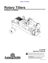
Quick-Push shear bolt
When the shear bolt is broken and the tine has been released, place the shear bolt one notch forward
before the machine can operate again.
Pull out the R-clip (Pos. 1).
Pull the tine back to normal working position (Pos. 2).
Push the shear bolt (Pos. 3) one notch forward to a new position in the
tine. Do not push the bolt totally through
(it can be necessary to remove soil etc. from the hole in the tine).
Important: All activities under the machine are deprecated when the
shear bolt is being moved or changed.
Push back the R-clip (Pos. 1), so that it locks the shear bolt in its place,
and the machine is ready for operation.
When the shear bolt is broken for the eighth time, it is used up.
Be aware that the shear bolt must never be shorter than 65 mm.
When a new shear bolt is mounted it is important that it is placed rightly.
The end of 40 mm (Pos. 3) is to turn away from the tine.
1
2
3

UK Combi-Tiller MK II 30/04-2019
10
Back to the table of contents
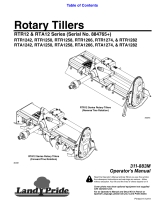
Hydraulic automatic release system
Before each season it has to be controlled, that the gas pressure in the accumulator
(Pos.1) is 90 bars. This requires special tools and can only be performed by an
authorized dealer.
Before the start-up of the machine the hydraulic pressure in the closed hydraulic stone
protection system has to be controlled on the machine’s pressure gauge (Pos. 2). The
pressure has to be minimum 100 bar and must not exceed 160 bar.
IMPORTANT – the hydraulic pressure is to be controlled continuously and must never be under 100
bar. If there is a need to adjust the working pressure, follow the below instructions:
Mount the quick coupling of the hydraulic hose (Pos. 3) in the tractor’s oil outlet.
Turn on the ball valve (Pos. 4), and the working pressure can now be adjusted up or down
with the tractor’s oil outlet.
When the desired pressure is achieved, turn off the ball valve again (Pos. 4), and the
tractor’s hydraulic system is relieved before the quick coupling (Pos. 3) is dismounted
and placed in the parking device of the machine.
During the operation of the machine the tine is swinging automatically to the rear if it meets an
obstacle. In normal circumstances the tine will automatically return to the working position again after
having passed the obstacle. At extreme obstacles and/or soil conditions it might be necessary to stop
and eventually lift the machine from the soil.
1
2
3

UK Combi-Tiller MK II 30/04-2019
11
Back to the table of contents
It is important that no persons are near to the machine as the tine is returning to
the working position with high speed and might throw with soil and stones.
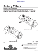
Replacement of wearing point
Before working with the machine’s wearing points, the machine is to be fastened.
This can be performed by trestles under the main frame.
Dismount M16x65 mm bolt (Pos. 1) by means of 2 pcs. 24 mm spanners. The
wearing point might fall off, when the bolt is removed – take care of foot and leg
injuries.
Dismount the wearing point by pushing it forward. This might be difficult due to
entrance of soil, and it might be a good idea to use a hammer.
Mount the new wearing point, item no. 645000044 (Pos. 2), by pushing the wearing point
to the rear and then in its place.
Check the M16 x 65 mm bolt for eventual damages and replace it as required, item no.
690103190 + 690113008.
Mount the M16 x 65 mm bolt (Pos. 1), lubricate and tighten it with approx 20 Nm.
Be carefull not to overtighten – the wearing point can be damaged
2
1


UK Combi-Tiller MK II 30/04-2019
13
Back to the table of contents
Maintenance
After 10 hours of operation, retighten the machine. Check hydraulic hoses, fittings and cylinders for
leaks and retighten.
Further check on a regular basis that all bolts are tightened.
Before the winter storage, wash and lubricate the machine. If you use high-pressure cleaner, do not
spray directly on the ball bearings. After the washing, you may spray the machine with oil.
Lubrication
For lubrication, maintenance and repair, lower the Sub-Tiller, put the brakes of the tractor on and stop
the motor.
The 3.0 m, 3.5 m and 4.0 m Combi-Tiller (rigid) have 5 lubricating points, and the 4.0 m and 5.0 m
Combi-Tiller (hydraulic) have 20 lubricating points, all Combi-Tiller models must be lubricated after
every 30 working hours as well as after the cleaning in order to press out any water and dirt. The
lubricating points on the rigid machines are located at the movable linkage and at the cylinder as well.
The lubricating points on the hydraulic models are furthermore located where the wing sections are
hinged on the middle section and at the support wheels.
Moreover, the machines with hydraulic automatic release system have 2 lubricating points per tine
which are to be lubricated after 10 hours of operation.
Important!
Oil, type Hydro Texaco HD32 has been
filled in the hydraulic system.
Lubricating point
X
X
X
X
X
X
X
XXX
XX
X
X
X
X
X

UK Combi-Tiller MK II 30/04-2019
14
Back to the table of contents
Frame and three-point linkage, rigid model
3.0 – 3.5 – 4.0 m
Pos.
Item no.
Designation
3.0 m
3.5 m
4.0 m
1
645200090
Frame
1
1
645200091
Frame
1
1A
645200213
Frame
1
1
645200092
Frame
1
2
69532100J
Pin for top link: Ø32 L=100
1
1
1
2A
69532105C
Pin for top link. Ø32/Ø45 L=105
1
3
690134008
Ring pin: Ø11, Ø60 ring
4
4
4
4
69537129B
Pin for lift arm: Ø37 L=129
2
2
2
4A
69537105C
Pin for lift arm: Ø37/Ø50 L=105
2
5
69440100G
Pin: Ø40 L=100
2
2
2
6
630532600
Lock bush for pin head
6
6
6
7
690101101
Bolt M12x25 8.8
6
6
6
8
69532119J
Pin for top link: Ø32 L=119
1
1
1
9
690302025
Top link
1
1
1
10
690200200
Cylinder 80/40x280 – plainØ30
2
2
2
10a
690200142
Gasket set 80/40 (Klinkby)
10a
690200143
Gasket set 80/40 (Laizhou)
11
69530175G
Pin: Ø30 L=175
2
2
2
12
645200170
Pointer at scale
1
1
1
13
69430125G
Pin: Ø30 L=125
2
2
2
14
690113006
Self-locking nut M12
4
4
4
15
690117014
Facet plate Ø12
4
4
4
16
690110050
U-bolt M12x40x40x40
2
2
2
17
645200113
Lift bracket
1
1
1


UK Combi-Tiller MK II 30/04-2019
16
Back to the table of contents
Support wheel
Pos.
Item no.
Designation
4.0 m
5.0 m
1
645200016
Frame
1
1
2
645200013
Support leg
1
1
3
690302025
Top link strengthened
1
1
4
69440155G
Pin Ø40 L=155
2
2
5
69530175G
Pin Ø30 L=175
2
2
6
69440187G
Pin Ø40 L=187
2
2
7
69532119J
Pin for top link Ø32 L=119
2
2
7A
69537129B
Pin for liftarm Ø37 L=129
2
2
8
690134008
Ring pin, Ø11,5, ring Ø60
4
4
9
630532600
Lock bush for pin head
6
6
10
690101101
Bolt M12x25 8.8
6
6
11
698500018
Label for scale
1
1
12
69516094A
Pin Ø16x94
1
1
13
690133005
R-clip Ø4
1
1
Pos.
Item no.
Designation
4.0 m
5.0 m
1
645200063
Wheel base, right
1
1

UK Combi-Tiller MK II 30/04-2019
17
Back to the table of contents
Drawbar
1
645200088
Wheel base, left
1
1
2
0395600
Complete wheel 200/60-14,5 10PR-5Rib
2
2
3
0395200
Hub
2
2
3a
0395270
Hub bolt M14x1,5 R14
10
10
3b
0395290
Wheel nut M14x1,5 R14
10
10
3c
0395260
Hub cap Ø62
2
2
4
690103117
Bolt M16x110 8.8
4
4
5
690117060
Facet plate Ø16
12
12
6
690302022
Top link M22 L=380-540
2
2
7
690113008
Self-locking nut M16
6
6
8
645200064
Bracket for support wheel, right
1
1
8
645200089
Bracket for support wheel, left
1
1
9
690103174
Bolt M16x220 8.8
2
2
10
0475307
Bush EG 40/30 L=25
4
4
11
645200066
BK-tube 30x5 L=155
2
2

UK Combi-Tiller MK II 30/04-2019
18
Back to the table of contents
Wing section
Pos.
Item no.
Designation
4.0 m
5.0 m
1
630931052
Drawbar
1
1
2
630771200
Parking device f/hoses
1
1
3
690200258
Cylinder 90/40x280mm Ø35/Ø32,5
1
1
3a
690200268
Gasket set 90/40 (Klinkby)
3a
690200274
Gasket set 90/40 (Laizhou)
4
69435153G
Pin Ø35 L=153
1
1
5
630532600
Lock bush for pin head
1
1
6
690101101
Bolt M12x25 8.8
1
1
7
690136029
Lubricating nipple M8
2
2
8
690200664
Distance clip ”blue” 6.2mm
1
1
9
690200665
Distance clip ”red” 9.4mm
1
1
10
690200666
Distance clip ”yellow” 18.8mm
1
1
11
690200667
Distance clip ”black” 36.1mm
1
1
12
690200668
Distance clip ”silver” 50.8mm
1
1
13
630757041
Towing eye w/bracket Ø50 pivotal 1x30°
1
1
14
630757023
Towing eye w/bracket – ball hitch
1
1
15
690113011
Self-locking nut M20
6
6
16
690117005
Facet plate Ø20
12
12
17
690103173
Bolt M20x70 10.9
6
6
Pos.
Item no.
Designation
4.0 m
5.0 m
1
645200191
Wing section, left
1
1
645200196
Wing section, right
1
1
645200197
Wing section, right
1
1
645200198
Wing section, left
1
2
69440155G
Pin Ø40 L=155
2
2
3
630532600
Lock bush for pin head
4
4
4
690101101
Bolt M12x25 8.8
4
2
5
69440827G
Pin Ø40 L=827
2
2
6
690136029
Lubricating nipple M8
2
2
7
690140715
Slide bush Ø40/44 L=40
4
4
8
690200255
Cylinder 90/40x500
2
2
8a
690200273
Gasket set 90/40 (Hydraflex)
8b
690200253
Square flange w/bushing Ø40,25
2
2
9
645200176
Shim 3 mm
2
2
9a
645200178
Shim 4 mm
2
2
9b
645200174
Shim 5 mm
2
2
10
690103200
Bolt M16x70 8.8
8
8
11
690117013
Facet plate Ø16
8
8
12
690113008
Self-locking nut M16
8
8
13
690136029
Lubricating nipple M8
2
2

UK Combi-Tiller MK II 30/04-2019
19
Back to the table of contents
Linkage
4.0 – 5.0 m hydraulic
Pos.
Item no.
Designation
4.0 m
5.0 m
1
645200171
Lift frame,
CAT II distance
1
1
1
645200231
Liftframe,
CAT III Quick couplung and CAT II distance
1
1
1a
690134006
Ball CAT 3/2 Ø64/Ø28,4
2
2
1b
690106011
Repairset f/Coupling Release KATIII
CBM typeII
2
690200200
Cylinder 80/40x280mm Ø30/Ø30
2
2
2a
690200143
Gasket set 80/40 (Laizhou)
2a
690200142
Gasket set 80/40 (Klinkby)
3
645200167
Pointer at scale
1
1
4
690110050
U-bolt M12 40x40x40
2
2
5
690117014
Facet plate Ø12
4
4
6
690113006
Self-locking nut M12
4
4
7
69430125G
Pin Ø30 L=125
2
2
8
630532600
Lock bush for pin head
2
2
9
690101101
Bolt M12x25 8.8
2
2
10
690136029
Lubricating nipple M8
4
4

UK Combi-Tiller MK II 30/04-2019
20
Back to the table of contents
Crossbar
Pos.
Item no.
Designation
4.0 m
5.0 m
1
645200207
Crossbar
1
1
2
69448140J
Pin Ø48 L=140
1
1
3
690134008
Ring pin Ø11,5 Ø60 ring
1
1
4
69537150B
Pin for lift arm Ø37 L=150 (CAT.III)
2
2
5
690103079
Bolt M10 x 130 10.9
2
2
6
690117012
Facet plate Ø10
4
4
7
690113005
Self-locking nut M10
2
2
/