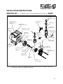
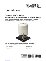
Stuart Turner FLOMATE MBF 12 Installation Instructions Manual
- Type
- Installation Instructions Manual
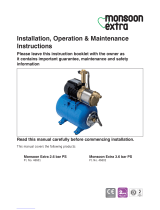
Stuart Turner FLOMATE MBF 12 is a versatile pump designed for domestic and light commercial use. It is capable of pumping clean water from various sources such as tanks, cisterns, and shallow wells. With a compact design and low noise operation, it is suitable for use in confined spaces and quiet environments. The MBF 12 features a mechanical seal for durability and extended lifespan. Additionally, it incorporates a non-return valve to prevent backflow and a flow regulator to maintain a consistent flow rate.
Stuart Turner FLOMATE MBF 12 is a versatile pump designed for domestic and light commercial use. It is capable of pumping clean water from various sources such as tanks, cisterns, and shallow wells. With a compact design and low noise operation, it is suitable for use in confined spaces and quiet environments. The MBF 12 features a mechanical seal for durability and extended lifespan. Additionally, it incorporates a non-return valve to prevent backflow and a flow regulator to maintain a consistent flow rate.


-
 1
1
-
 2
2
-
 3
3
-
 4
4
-
 5
5
-
 6
6
-
 7
7
-
 8
8
-
 9
9
-
 10
10
-
 11
11
-
 12
12
-
 13
13
-
 14
14
-
 15
15
-
 16
16


Stuart Turner FLOMATE MBF 12 Installation Instructions Manual
- Type
- Installation Instructions Manual
Stuart Turner FLOMATE MBF 12 is a versatile pump designed for domestic and light commercial use. It is capable of pumping clean water from various sources such as tanks, cisterns, and shallow wells. With a compact design and low noise operation, it is suitable for use in confined spaces and quiet environments. The MBF 12 features a mechanical seal for durability and extended lifespan. Additionally, it incorporates a non-return valve to prevent backflow and a flow regulator to maintain a consistent flow rate.
Ask a question and I''ll find the answer in the document
Finding information in a document is now easier with AI
Related papers
-
 Stuart Turner mainsboost MBF 80-1-15 Installation & Maintenance Instructions Manual
-
Stuart Turner 46523 Installation, Operation & Maintenance Instructions Manual
-
 Stuart Turner 46503 EXP Installation, Operation & Maintenance Instructions Manual
-
 Stuart Turner Jet 80-45 B Installation, Operation & Maintenance Instructions Manual
-
 Stuart Turner 46601 Installation, Operation & Maintenance Instructions Manual
-
 Stuart Turner Monsoon Extra S1.4 bar Installation, Operation & Maintenance Instructions Manual
-
 Stuart Turner CH 4-30 B Installation, Operation & Maintenance Instructions Manual
-
 Stuart Turner Flomate iBoost 46668 Installation, Operation & Maintanance Instructions
-
 Stuart Turner 49081 Installation, Operation & Maintenance Instructions Manual
-
 Stuart Turner ABB V260-85-2V-1 Installation, Operation & Maintenance Instructions Manual


Other documents
-
 Stuart Boostamatic K7-2 Operating Instructions Manual
-
Bristan ST PUMP15TN Installation, Operation & Maintenance Instructions Manual
-
Hobart H-600 User manual
-
Champion 94 FFPW User manual
-
Champion PP-28FF User manual
-
-
-
-
-
