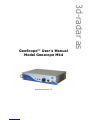
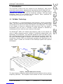
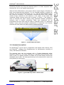
3d-Radar Geoscope Mk4 is a state-of-the-art Ground Penetrating Radar (GPR) system designed to locate buried infrastructure without the need for excavation or disruption to services. It has a variety of applications, including utility mapping, archaeological surveys, and environmental site characterization. The Geoscope Mk4 is a powerful and versatile tool that can be used to quickly and easily identify and map buried objects.
Some of the key features of the Geoscope Mk4 include:
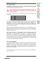
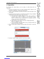
- High-resolution imaging: The Geoscope Mk4 uses a high-frequency antenna array to produce detailed images of buried objects. This allows users to clearly identify and map even small objects, such as utilities, archaeological features, and environmental hazards.
3d-Radar Geoscope Mk4 is a state-of-the-art Ground Penetrating Radar (GPR) system designed to locate buried infrastructure without the need for excavation or disruption to services. It has a variety of applications, including utility mapping, archaeological surveys, and environmental site characterization. The Geoscope Mk4 is a powerful and versatile tool that can be used to quickly and easily identify and map buried objects.
Some of the key features of the Geoscope Mk4 include:
- High-resolution imaging: The Geoscope Mk4 uses a high-frequency antenna array to produce detailed images of buried objects. This allows users to clearly identify and map even small objects, such as utilities, archaeological features, and environmental hazards.


-
 1
1
-
 2
2
-
 3
3
-
 4
4
-
 5
5
-
 6
6
-
 7
7
-
 8
8
-
 9
9
-
 10
10
-
 11
11
-
 12
12
-
 13
13
-
 14
14
-
 15
15
-
 16
16
-
 17
17
-
 18
18
-
 19
19
-
 20
20
-
 21
21
-
 22
22


3d-Radar Geoscope Mk4 is a state-of-the-art Ground Penetrating Radar (GPR) system designed to locate buried infrastructure without the need for excavation or disruption to services. It has a variety of applications, including utility mapping, archaeological surveys, and environmental site characterization. The Geoscope Mk4 is a powerful and versatile tool that can be used to quickly and easily identify and map buried objects.
Some of the key features of the Geoscope Mk4 include:
- High-resolution imaging: The Geoscope Mk4 uses a high-frequency antenna array to produce detailed images of buried objects. This allows users to clearly identify and map even small objects, such as utilities, archaeological features, and environmental hazards.
Ask a question and I''ll find the answer in the document
Finding information in a document is now easier with AI
Other documents
-
Uhuru WM-02Z User manual
-
Continental ARS5A User guide
-
Radiodetection RD1100 Owner's manual
-
Radiodetection RD1500 GPR : Quick Start User Guide and Owner's manual
-
Standard Horizon MDS-8 User manual
-
-
FLIR Elara™ R-290 User manual
-
Asus MAXIMUSVIIMPACT User manual
-
Simrad Pulse Compression Radar Installation guide
-
 Kelvin Hughes CICDTX-A1 User manual
