Page is loading ...

E
Installation Instructions
and User Guide
Artisan Evo
Digital Electronic Mixer Shower
Models Covered:
ARDE SHCDIVM C
Please keep this booklet for future
reference.
Installer, when you have read these
instructions please ensure you leave
them with the user.

Contents
• Important Safety Information 3
• Specification 4
• Product Features 5
• Dimensions (mm) 6
• Installation Requirements 6-9
• Installation 9-13
• Commissioning 14-17
• Operation 17-19
• Maintenance 19-21
• Troubleshooting 22
• Spares 23
Need help? Give us a call on 0330 026 6273 and speak to one of our trained advisors.
Contents
2
Welcome to your new Bristan Digital Electronic Mixer Shower, featuring a
contemporary design, wireless electronic controller and digital mixing unit.
Bristan’s Digital Electronic Mixer Shower has been designed to be easy to
install and use. It has also been designed and tested in the UK to all of the
relevant British Standards.
These instructions are for your guidance to a safe and successful installation,
so please read them thoroughly and retain for future reference.
We recommend the installation is carried out by a suitably qualified person
and must conform with current I.E.E Wiring Regulations (BS7671) and Building
Regulations (Part P and Part G).

Please read these instructions thoroughly and retain for future use.
All products manufactured and supplied by Bristan are safe provided they are
installed, used correctly and receive regular maintenance in accordance with these
instructions.
If you are in any doubt about your ability to install this product safely you must
employ the services of an experienced qualified plumber/electrically qualified person.
This Digital Electronic Mixer Shower needs to be installed in accordance with, and
meet the requirements of the Water Supply (Water Fittings) Regulations 1999 and
current byelaws.
Before starting any installation please consider the following:
Before drilling into walls, check that there are no hidden electrical wires, cables or
water supply pipes. This can be checked with the aid of an electronic detector.
If power tools are used do not forget to: - Wear eye protection
- Unplug equipment after use
Warning: Before installing the new Digital Electronic Mixer Shower it is
essential that you thoroughly flush through the pipework in order
to remove any remaining swarf, solder, etc. Failure to carry out this procedure could
cause problems or damage to the workings of the Mixing Valve.
Do not operate the shower if the water stops flowing during use or if the water is
leaking from the Mixing Valve itself. Turn o at the mains electrical supply and refer to
the Troubleshooting section (see page 22) or contact Bristan Customer Services on
0330 026 6273.
Do not block the flow of water from the showerhead, by placing it (smothering it) on
your hand or any other part of your body or foreign object.
Do not crush or kink the shower hose, this could damage the hose and cause leaks.
Warning: Do not operate this product if you suspect it is frozen. Do not site
the Mixing Valve where it might be subjected to freezing conditions.
BEAB (British Electro-
technical
Approvals Board) approval
of safety.
Hereby, Bristan Group Ltd, declares that this Electronic Mixing
Valve with Wireless Controller is in compliance with the essential
requirements and other relevant provisions of the Directive 1999/5/
EC. The declaration of conformity may be consulted at www.bristan.
com/dop.
Need help? Give us a call on 0330 026 6273 and speak to one of our trained advisors.
Important Safety Information
3

Heavy
Commercial
If the inlets are pumped, a
Bristan Twin-End Negative Head Pump
(ST NHPUMP 18TN) must be used.
Scan the QR Code for more details.
E
5°C
52°C
20°C
65°C
Light
Commercial
Maximum Static Pressure: 10.0 Bar
Inlet Water Temperature
Outlet Connection
Min: 0.5 Bar
Max: 5.0 Bar
Working Pressures
230V AC, 35W
Suitable for high pressure
systems only
Inlet Connection
Cold Water Supply
Hot Water Supply
Min: 5°C Max: 20°C
Min: 52°C Max: 65°C
Tools You’ll Need
1/2” BSP
1/2” BSP
Flow Performance
Recommended Usage
Healthcare
Pack Contents
Flat-head Screwdriver
Cross-head Screwdriver
Pencil
Drill
Masking TapePliersPipe & Wire Detector
Spirit Level
Domestic
Electrical Requirements
Supply Requirements
IMPORTANT
Specifications
x4
x1
x3
x1
x1
x1
x1
Prior to Installation
All products manufactured and supplied by Bristan are safe provided
they are installed, used correctly and recieve regular maintenance in
accordance with these instructions.
This product has been tested to the Water Regulations Advisory
Scheme (WRAS) and satisfies the requirements of the Water Supply
(Water Fittings) Regulations 1999 and current bylaws.
For full Installation Requirements & Notes (IRN) please visit
wras.co.uk/directory.
Remove all packaging and check the contents for damage before
starting any installation.
Fitting isolation valves to the inlet feeds is required as close as is
practical to the inlet connections for ease of maintenance.
Before installing this product the water supply must be thoroughly
flushed in order to remove any swarf, solder etc.
Always switch o the power at the consumer unit and isolate the
electrical supply before making any electrical connections or
if you have to remove the cover of the Mixing Valve.
This product must not be modified in any way as this will
invalidate the guarantee.
Flow Setting Optimum Flow Rate (lpm)
6 lpm
8 lpm
10 lpm
12 lpm
Adjustable Spanner
x1
x1
x1
x1
x1
x1
70mm
Centres
Optimum Minimum Pressure: 1.0 Bar
x7
1.0
5.0
4.0
3.02.0
Pressure
BAR
0
1.0
5.0
4.0
3.02.0
Pressure
BAR
0
Need help? Give us a call on 0330 026 6273 and speak to one of our trained advisors.
Specification
4

1. Temperature control
Press to increase the temperature up to a
factory set maximum of 48ºC (the maximum
temperature can be overridden, see Maximum
Temperature Setting on page 17).
Press to decrease the temperature down to
a minimum of 35ºC.
2. Lever handle
Turns the shower on and adjusts the flow of
water. Turn anti-clockwise to turn the shower
on and back to to turn the shower o.
3. Water flow settings
The shower has 4 flow settings.
Eco ( ), Low ( ), Medium ( ), and
High( ).
4. Digital display screen
Displays the water temperature . Any error
codes will be displayed on here.
5. Time out mode
If the shower has been running for 30 minutes
the Mixing Valve will automatically shut o to
save water and energy.
Normal use will be resumed once the lever
handle has been returned to the ‘O’ position.
6.Memory function
(Available with Chrome variants only)
Allows two temperature and flow pre-sets to be
stored and used for quick control.
Note: Artisan Evo is designed for only one
controller; it is not possible to add a second
controller
1
2
4
3
E
6
E
Need help? Give us a call on 0330 026 6273 and speak to one of our trained advisors.
5
Product Features

86
123
212
226
70
200
223
40
45
DO NOT INSTALL UPSIDE DOWN
ON THE WALL!
DO NOT INSTALL HORIZONTALLY
ON THE WALL!
1068
Installation Requirements
Positioning the Mixing Valve
The Mixing Valve can be positioned on
either a wall surface or flat on the floor.
(Refer to the diagrams for the correct
orientation of the Mixing Valve).
The Mixing Valve can be installed in either
an airing cupboard, loft space or under
the bath. Do not site the Mixing Valve
where it may be subjected to freezing
conditions or ambient temperatures over
40ºC.
The maximum distance from the Mixing
Valve to the Wireless controller must not
exceed 10 metres as this is beyond the
operating range of the wireless controller.
E
Need help? Give us a call on 0330 026 6273 and speak to one of our trained advisors.
Dimensions (mm)
6

Positioning the Mixing Valve
Vertically up on the wall
Vertically down on the wallFlat on the floor
E
Minimum 20mm
between
showerhead and
spillover
Wall
outlet
Controller
Hose
Retainer
Bath spillover
level
Shower tray
spillover level
Water Requirements
This fitting needs to be installed in
accordance with the following Installation
Requirements and Notes (IRN) to ensure
they meet the requirements of the Water
Supply (Water Fittings) Regulations 1999
and the current Bylaws.
The fitting shall be installed so that its
outlet discharges above the spill-over
level of any appliance as indicated on the
illustration below:
Wireless Installation
Considerations
As with any wireless/radio product:
- Metallic lined materials or metal
objects (such as steel baths or
metal tanks, etc.) can
significantly reduce the
operating range of the wireless
interface or prevent operation.
- Interference from other radio
signals has the potential to
aect the ability of the wireless
interface to function correctly.
Note: If the Mixing Valve loses wireless
communication with the
controller, the shower will
automatically turn o safely.
Need help? Give us a call on 0330 026 6273 and speak to one of our trained advisors.
7
Installation Requirements

Water Requirements
For backflow protection in premises or
installations up to, and including Fluid
Category 3 and 5.
The vertical distance of the outlet above
the spill-over level shall be not less than
20mm or twice the diameter of the inlet
pipe to the fitting, which ever is greater. If
the fitting cannot be installed as indicated
it shall be installed with a backflow
prevention arrangement suitable for the
Fluid Category.
Warning: The shower must not
be installed in an area
subject to freezing conditions. Do not use
if you suspect the shower is frozen, this
will damage the shower unit.
A minimum working inlet pressure of
0.1MPa (1 bar) at a minimum flow rate of 10
litres per minute is recommended for full
performance.
The maximum static inlet pressure must
not exceed 1.0MPa (10bar).
If it is intended to operate the shower
above the recommended operating/
dynamic pressure, a suitable pressure
reducing valve (PRV) should be used.
Maximum ambient temperature: 40°C.
Note: If a showerhead can sit within a
bath, basin or shower tray,
Water Regulations stipulate a double check
valve must be fitted in the supply pipe
work to prevent back siphonage*. If the
shower head can sit within a WC then the
air gap should be a type AUK3 not less
Electrical Requirements
Warning: This appliance MUST
be earthed!
Power Rating: 230V AC / 35W
The Electricical Installation and Curcuit
Protection of this shower must comply
with current I.E.E Wiring Regulations (BS
7671) and Building Regulations (Part P).
We recommend that this Digital
Electronic Mixing Shower is installed by
a qualified electrician prior to use. The
following notes are for your guidance
only.
than 20mm or twice the diameter of the
inlet pipe to the fitting, whichever is the
greater.
* As this shower unit is already supplied
with a single check valve pre-fitted in
each water supply inlet, a further single
check valve would be required in such a
situation, fitted in each water supply as
close as possible to the existing check
valves
Water regulations stipulate that a
removable showerhead be constrained
by a fixed or sliding attachment (hose
retainer supplied) so that it can only
discharge water at a point not less that
20mm above the spill-over lever of
the bath or shower tray or other fixed
appliance.
If the shower is to be installed in a hard
water area, we recommend that an in-line
scale inhibitor is fitted which will prolong
the life of the shower. Please refer to your
supplier for advice.
Need help? Give us a call on 0330 026 6273 and speak to one of our trained advisors.
Installation Requirements
8

Electrical Requirements
Important: You must switch o the power at the consumer unit,
isolate the electrical circuit and verify the earth before
making any electrical connections.
The Mixing Valve must only be connected to a 230-240V AC supply. This product
must be connected to a fused spur with double-pole isolation and a 3A fuse.
It is recommended that a residual current device (RCD) formerly known as an earth
leakage circuit breaker (ELCB) with a tripping current of 30mA, incorporated in the
circuit. This may be part of the existing consumer unit or a seprate unit.
For close circuit protection DO NOT use a rewireable fuse. Instead use a suitably
rated miniature circuit breaker (MCB) or Cartridge Fuse.
Do not turn on the electrical supply until the plumbing has been completed and the
Mixing Valve cover re-fitted (if removed).
Installation
Fixing the Mixing Valve to the
floor/wall
Please refer to ‘Positioning the Mixing
Valve’ on before starting any installation.
The Mixing Valve needs to be installed
on either a flat floor or a wall surface.
Position the Mixing Valve on the floor or
wall surface and mark all 4 fixing points.
Fixing Points
IMPORTANT
Prior to drilling
check there
are no hidden
electrical cables
or water supply
pipes
Need help? Give us a call on 0330 026 6273 and speak to one of our trained advisors.
9
Installation Requirements

Plumbing Connections
Warning: Do not solder within
300mm of the Mixing
Valve or allow solder or flux to fall onto
the casing.
Important:
An additional independant stop valve
complying with the current water
regulations must be fitted in the mains
water supply as a means of isolating the
supplys to the Mixing Valve for servicing
and/or maintenance work.
It is essential that all pipe work is flushed
through to remove debris and swarf that
could otherwise damage the unit.
Once the pipework has been flushed
through, turn o the water supplies at the
stop/service valves.
Pumped Inputs
It is possible to use a pump to boost a
low pressure system to meet the inlet
requirements.
Note: The pump must be a Bristan Twin-
End Negative Head Pump - ST NHPUMP
18TN.
Pump installation must be in accordance
with the Fitting Instructions supplied with
the pump.
The Negative Head Pump is required
to maintain the 0.5 bar minimum static
pressure requirement.
Fixing the Mixing Valve to the
floor/wall
If you are fitting the Mixing Valve to a
partition wall, a wall of particularly friable
(crumbly) substrate or a wooden floor you
will need appropriate fixings for the floor/
wall type.
Drill suitable holes in the floor/wall surface
at the marked positions and insert wall
plugs (if required).
Secure the Mixing Valve to the floor/
wall surface using the fixings supplied or
suitable fixings dependant on floor/wall
type.
Important:
Under no circumstances should the mixing
valve be recessed as this may prevent air
circulating and condensation escaping.
Need help? Give us a call on 0330 026 6273 and speak to one of our trained advisors.
Installation
10

Plumbing Connections
The filter washers supplied must be
fitted into both inlets.
The connecting pipework must present
1/2 BSP connectors to the male thread
on the inlet connections.
Important:
The pipework must run as straight as
possible to the Mixing Valve minimising
90º angled bends as this could aect
the inlet pressure to the Mixing Valve
reducing performance.
Electrical Connections
The electrical installation must be
carried out in accordance with the
current I.E.E Wiring Regulations (BS 7671)
and Building Regulations (Part P).
Warning:
This appliance and all connecting metal
pipework must be earthed via the supply
cord, which must be correctly connected
to the earth point located in the terminal
box.
The Mixing Valve must be permanently
connected to the fixed wiring of the
mains supply using the factory fitted
supply cord, via a double pole switched
fused spur o the ring main.
In the interests of electrical safety a
30mA residual current device (R.C.D.
not supplied) should be installed in the
supply circuit. This may be part of a
consumer unit or a separate unit.
Wiring of Connection Unit:
Warning: This appliance must be earthed.
The wires in the mains lead are coloured
in accordance with the following code:
Green and
Yellow
Earth
Blue Neutral
Brown Live
As the colours of the wires in the mains
lead of this appliance may not correspond
with the coloured markings identifying the
terminals in your connection unit proceed
as follows:
The wire which is coloured green and
yellow must be connected to the terminal
in the connection unit which is marked
with the letter E or by the earth symbol or
coloured green or green and yellow.
The wire which is coloured blue must be
connected to the terminal which is marked
with the letter N or coloured black.
The wire which is coloured brown must be
connected to the terminal which is marked
with the letter L or coloured red.
Why not Visit our
Youtube Channel?
To see our latest how-to videos,
simply scan the QR code with your
smart phone or tablet.
Alternatively visit www.youtube.com/bristantv
Need help? Give us a call on 0330 026 6273 and speak to one of our trained advisors.
11
Installation

Fitting the Wireless Controller
Remove the locking ring and wall bracket
from the wireless controller by twisting
the locking ring clockwise.
Position the wall bracket onto the
finished wall surface and mark the fixing
holes.
Drill holes at the marked
positions on the wall
surface using a
suitable drill bit for
the fixings.
Secure the wall bracket
to the wall using the
fixings supplied or
suitable fixings for the wall type,
ensuring the locking ring is positioned
behind the fixing bracket.
Once the wall bracket is secured to the
wall surface turn the locking ring so
that one of the four fixing lugs is at a 12
o’clock position.
Fit the remote control onto the locking
ring. Twist the locking ring anti-clockwise
to lock the remote control into postition.
Wall
Bracket
Locking Ring
Wall
Bracket
Twist locking ring
anti-clockwise
to lock.
Fixing Lug
IMPORTANT
Prior to drilling
check there
are no hidden
electrical cables
or water supply
pipes
Using masking tape
when marking out
help prevent the drill
bit from wandering
when drilling
Need help? Give us a call on 0330 026 6273 and speak to one of our trained advisors.
12
Installation

4
IMPORTANT:
When working near a basin, bath or shower
insert plug or cover waste to prevent losing small parts.
Take care not to drop tools/equipment into basin,
bath or shower during installation.
1
2
3
5
4
6
Connect the water supply
to the diverter inlet and secure to
the wall. Screw the riser rail into
the top of the diverter.
Position the fixing
bracket against
the wall, ensuring
it’s straight.
Mark the fixing
positions and
remove from
the wall.
Screw the
shower rose
on to the arm,
ensuring the
washers are in
place.
Connect the hose
to the handset and
place in the slider.
Your shower is now ready
to be commissioned
for first use.
Screw the
hose on to
the diverter
outlet.
Remove the wall bracket fixing.
Secure the wall bracket to the
wall surface. The bracket is
adjustable to suit dierent
wall types.
Using masking tape
when marking out
help prevent the drill
bit from wandering
when drilling
IMPORTANT
Prior to drilling
check there
are no hidden
electrical cables
or water supply
pipes
Installation
Need help? Give us a call on 0330 026 6273 and speak to one of our trained advisors.
13

If the Mixing Valve LED stays “Yellow”, the
Wireless Connection is not configured
correctly. Proceed with the Initialise (2)
and Pairing (3) steps.
Additionally, it may also be necessary
to perform the Initialisation and Pairing
(Steps 2 & 3), if:
- You have a replacement unit
(either the Mixing Valve or Remote
Control).
- The pre-set address used for the
Pairing is used on a neighbouring Artisan
Evo installation
IMPORTANT: Both the Initialisation and
Pairing steps must be performed in
sequence.
2. Initialise the Remote Control Wireless
Address.
2.1. Turn the Remote Control “on” by
turning the lever to the “eco” position.
a. If the display shows a flashing 2-digit
number, e.g. “30”. Proceed to step (2.2).
b. If the display shows a single flashing
“0” , press the Temp up button ten
times to increment the flashing number
from “0” to “9”, and then to a flashing
2-digit number, e.g. “30”. This has now
Initialised the Remote Control - proceed to
Pairing (3).
Wireless Initialisation &
Pairing of the remote control
to mixing valve
For the wireless communication to
work, the Remote Control needs to be
initialised and paired with the Mixing
Valve. This is pre-configured upon
manufacturing of the product, so the
product should work “out-of-the-box”.
1. Check the Wireless Communication
is configured correctly.
Ensure the Remote Control is equipped
with the 2 x AA batteries supplied and
the flow lever is in the position (6
o’clock).
Isolate both hot and cold water supplies
to the Mixing Valve and turn the power
to the Mixing Valve o.
1.1. Power on the Mixing Valve. The LED
will initially show “Green”. Wait for ˜30
seconds, the LED will show “Yellow” to
indicate “No wireless connection”.
1.2. Turn the Remote Control “on”
by turning the flow lever to “eco”
position (5 o’clock). The Mixing Valve
LED should return to “Green” in a
few seconds to indicate wireless
communication. Turn the Remote
Control “o” by turning the lever back to
and turn the power o to the Mixing
Valve.
If the Mixing Valve LED returns to
“Green”, the product is Initialised and
Paired correctly and no further action is
required.
E
E
Need help? Give us a call on 0330 026 6273 and speak to one of our trained advisors.
Commissioning
14

3.4. Power down the Mixing Valve.
Remove the cover from the Mixing Valve,
set switch 4 at SW1 to “o” and replace
the cover. The Mixing Valve and Remote
Control are now Paired.
Maximum Temperature Setting
The maximum temperture is factory
pre-set to 48ºC. To change the maximum
outlet water temperature follow the steps
below.
1. Power down the Mixing Valve and
remove the cover.
2. Locate the block of four switches
marked SW1 on the circuit board.
Position the individual switches as per the
following diagrams:
Note: Only switches 1-3 need to be altered.
38ºC
SW1-1 OFF
SW1-2 OFF
SW1-3 OFF
41ºC
SW1-1 ON
SW1-2 OFF
SW1-3 OFF
44ºC
SW1-1 OFF
SW1-2 ON
SW1-3 OFF
2.2. Enter Engineering Mode: press and
hold both the Temp up and Temp
down buttons together for more than
three seconds, then release.
Note: If “2” is displayed, press Temp
down button twice to read “0”.
2.3. Press the Temp up or Temp
down button to change the number
until “2” is displayed, The “2” will stay
displayed for ˜2 seconds, and then
change to a flashing “0”.
2.4. Press the Temp up button ten
times to increment the flashing number
from “0” to “9”, and then to steady-state
“2” or ‘E1’. This has now Initialised the
remote control.
2.5. Exit Engineering Mode: Press the
Temp down button twice to change
the displayed number back to “0”,
and/or turn the Remote Control “o” by
turning the lever back to .
3. Pairing the Remote Control to the
Mixing Valve.
3.1. Remove the cover from the Mixing
Valve and locate the block of four
switches marked SW1 on the circuit
board. Set switch 4 to ‘ON’ and loosely
replace the cover.
3.2. Power up the Mixing Valve. Wait ˜30
seconds for the LED to show “Yellow”.
3.3. Turn the remote control “on” by
turning the lever to the eco position.
Wait for the Mixing Valve LED to show
“Green” (this should only take a couple
of seconds). Turn the Remote Control
“o” by turning the lever back to the
“o” position.
E
ON
1 2 3 4
ON
1 2 3 4
ON
1 2 3 4
Need help? Give us a call on 0330 026 6273 and speak to one of our trained advisors.
15
Commissioning

Turn on the water supplies to the Mixing
Valve and open the stop / service valves
to the mixing valve.
Check that there are no leaks around the
connections to the inlets and outlet.
Purge Procedure
After checking the water / plumbing
connections and before using the shower
as normal the Mixing Valve will need to be
purged. Please run through the following
procudure.
1. Ensure both power and water supplies
to the Mixing Valve are on.
2. Turn the Controller On by rotating the
lever to any of the flow positions. The
shower will run.
3. Press and buttons at the same
time for 3 or more seconds then let go.
4. ‘0’ should be displayed. If not repeat
step 3.
5. Press button once. ‘1’ should be
displayed.
6. The purge sequence will now run.
(Short pulses of water output from the
shower for about 12 seconds).
7. Once the pulsing stops, turn the
Controller O.
8. To resume normal showering, simply
turn the Controller on as normal.
46ºC
SW1-1 ON
SW1-2 ON
SW1-3 OFF
48ºC
SW1-1 OFF
SW1-2 OFF
SW1-3 ON
Once the switches have been altered,
to the desired position the maximum
temperature is set.
3. Replace the Mixing Valve cover and
secure with the five fixing screws.
IMPORTANT:
It is important to power down the Mixing
Valve to change the switch settings as
they are only read on power up.
Checking Water / Plumbing
Connections
Before using the shower for the first time
the installer needs to check that the
water/plumbing connections are correct.
The cold water supply pipework should
only be connected to the inlet marked
COLD on the Mixing Valve cover.
The hot water supply pipework should
only be connected to the inlet marked
HOT on the Mixing Valve cover.
ON
1 2 3 4
ON
1 2 3 4
Need help? Give us a call on 0330 026 6273 and speak to one of our trained advisors.
Commissioning
16

Basic Functional Testing
Prior to using the shower the following
tests should be carried out to ensure
the Mixing Valve is working correctly.
Power on the Mixing Valve.
Check the display on the Remote
Control is working.
Check Flow Control.
Operate the lever to all flow positions
and check for increased flow.
Check Temperature controls.
Press the up and down
temperature buttons to check that the
temperature increases and decreases.
Check Digital Display.
Ensure the temperature display increases
and decreases when pressing the
temperature controls.
Please ensure the commissioning
procedure has been carried out. If you
did not fit this shower yourself and you
are about to use it for the first time,
check with the installer to ensure they
have run the commissioning procedure
as described.
To Start the Shower
Turn the lever (1) anti-clockwise.
To Stop the Shower
Turn the lever (1) clockwise back to .
Warning: This appliance is not intended for use by
persons (including children) with reduced physical,
sensory or mental capabilities, or lack of experience
and knowledge, unless they have been given supervision
or instruction concerning use of the appliance by a person
responsible for their safety.
E
1
E
Commissioning
Need help? Give us a call on 0330 026 6273 and speak to one of our trained advisors.
17
Operation

Important: Children should be supervised to ensure
that they do not play with the appliance.
Operating the controls
Temperature Control
Flow Control
Hot
Cold
Low Battery Warning Light
Eco Water Saving Mode
Low Flow
Medium Flow
High Flow
Memory
Button
E
Memory Function
Only available on Chrome variants.
The Memory Function allows the user to
store Temperature and Flow pre-sets,
and recall them to set the shower to their
desired settings at a single touch of a
button.
The memory Button has two settings,
Memory 1 and Memory 2, indicated by
two lights.
E
E
Need help? Give us a call on 0330 026 6273 and speak to one of our trained advisors.
18
Operation

To Store a Memory Setting
1. Turn Shower On by moving Flow Lever
anti-clockwise from the O position.
2. Select desired Temperature by using
“+” and “-” buttons as normal.
3. Select desired Flow by adjusting the
Flow Lever as normal.
4. Press-and-hold the Memory Button
“M”. The Digital Display will toggle
repeatedly between “1” and “2”.
5. To Store in Memory 1, wait until the
display shows “1” and then release the
“M” button.
6. To Store in Memory “2”, wait until the
display shows “2” and then release the
“M” button.
The desired Temperature and Flow
settings are now stored in the desired
Memory Setting.
To Recall a Memory Setting
1. Turn Shower On by moving Flow Lever
anti-clockwise from the O position.
2. To recall a specific memory setting,
press-and-release the “M” button until the
requied number (“1” or “2”) is shown in the
Digital Display.
3. The Controller will then set Temperature
and Flow (regardless of the actual position
of the lever) to the stored settings.
The Shower’s Temperature and Flow can
be adjusted in the normal way using the
Temperature buttons and Flow lever.
Any use of the Temperature Buttons will
override the Memory Temperature Setting
and revert to manual temperature contol.
Any use of the Flow Lever will override
the Memory Flow Setting and revert to
manual flow control.
Maintenance
General Cleaning
Your fitting has a high quality finish and should be treated with care to preserve the
visible surfaces. All surfaces will wear if not cleaned correctly, the only safe way to
clean your product is to wipe with a soft damp cloth. Stains can be removed using
washing up liquid.
All bath cleaning powders and liquids will damage the surface of your fitting,
even the non-scratch cleaners.
Note: Never use abrasive detergents or disinfectants or those containing
alcohol, hydrochloric acid or phosphoric acid.
Operation
Need help? Give us a call on 0330 026 6273 and speak to one of our trained advisors.
19

NRV & Filter Maintenance
The Mixing Valve is supplied with a
Non-Return Valve fitted into each inlet.
The filter washers which seal the inlet
and connection may become scaled
over in particularly hard water areas and
may need cleaning on a regular basis to
ensure maximum performance.
Cleaning the Filters
Isolate both hot and cold water supplies
to the Mixing Valve and remove the
connections from the inlets.
Run both filter washers under running
water and rub your fingers over the
mesh to remove any build up of scale.
Replacing the NRVs
Isolate both hot and cold water supplies
to the Mixing Valve and remove the inlet
connections. Remove the filter washers
and inserts from the inlets. Carefully
prise out the NRVs from the inlets using
a small thin bladed tool i.e. flat head
screw driver. Insert new NRVs back into
the inlets and replace the inserts and
filter washers.
Re-fit the inlet connections ensuring they
are fully tightened.
Filter
Washer
Insert
NRV
Battery Replacement
The Wireless Controller is powered by
two AA batteries which are designed
to last approximately 1 year based on
average showering usage before they
need replacing.
When the batteries run low and require
replacing, the red low battery LED on the
front face of the display will flash.
Red low
battery LED
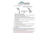
Cleaning the Showerhead
Your Bristan showerhead has rub-clean
nozzles for easy cleaning. Simply rub
your fingers across the rubber spray jets
regularly and before you turn the shower
on to remove any scale or debris.
The hardness of the water in your area
will determine how often you should clean
your showerhead. Build up of scale in
particularly hard water areas combined
with constant use means you may need
to clean your showerhead once a week.
To ensure continued performance of
your shower the showerhead needs to be
regularly descaled.
Need help? Give us a call on 0330 026 6273 and speak to one of our trained advisors.
20
Maintenance
/