
32
L32W961

TABLE OF CONTENT
DIGITAL TELEVISION TRANSITION NOTICE .......................................1
FOR YOUR SAFETY........................................................................................ 2
PRECAUTIONS AND REMINDERS ...........................................................3
IMPORTANT SAFETY INSTRUCTIONS...................................................4
PACKAGE CONTENTS.................................................................................5
PREPARATION.................................................................................................6
ATTACHING THE BASE.........................................................................................................6
PREPARING YOUR LCD HDTV FOR WALL MOUNTING..........................................6
PERIPHERAL CONNECTION GUIDE......................................................8
OPERATING INSTRUCTIONS....................................................................9
TO USE THE FRONT PANEL CONTROL.........................................................................9
TO USE THE REMOTE CONTROL.................................................................................. 10
VIEWING MODELS ILLUSTRATIONS............................................................................ 11
CONNECTING EQUIPMENT........................................................................................... 13
TO USE THE MENUS........................................................................................................... 19
CHANNEL MENU................................................................................................................ 19
VIDEO MENU........................................................................................................................ 19
AUDIO MENU....................................................................................................................... 20
FEATURE MENU....................................................................................................................20
VGA MENU............................................................................................................................. 22
TIPS........................................................................................................................................... 23
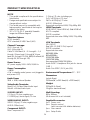
PRODUCT SPECIFICATION......................................................................24
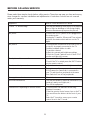
BEFORE CALLING SERVICE......................................................................25
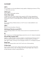
GLOSSARY......................................................................................................26

1
DIGITAL TELEVISION TRANSITION NOTICE
This device contains a digital television tuner, so it should receive digital over the air TV programming,
with a suitable antenna, after the end of full-power analog TV broadcasting in the United States on June
12, 2009. Some older television receivers, if they rely on a TV antenna, will need a TV Converter to
receive over the air digital programming, but should continue to work as before for other purposes (e.g.,
for watching low-power TV stations still broadcasting in analog, watching pre-recorded movies, or playing
video games).
For more information,
call the FCC at 1-888-CALL-FCC (1-888-225-5322)
or see www.DTV.gov.
For information on the TV Converter program, and on government coupons that may be used toward
the purchase of one, see www.dtv2009.gov,
or call the NTIA at 1-888-DTV-2009
.
AVISO RELATIVO A LA TRANSICIÓN A TELEVISIÓN DIGITAL
Este equipo incorpora un sintonizador de televisión digital, lo que le permitirá recibir una programación
digital televisada por aire, con una antena adecuada, cuando se terminará la transmisión de alta potencia
de la televisión analógica en los Estados Unidos el 12 de junio de 2009. Ciertos receptores de televisión
antiguos, si dependen de una antena de TV, necesitarán un conversor de TV para recibir por el aire una
programación digital, pero seguirán funcionando como antes para otros usos (por ejemplo para ver
emisoras de TV de baja potencia que todavía transmiten en analógico, para ver películas pregrabadas, o
para utilizar sus videojuegos).
Para obtener más información,
llame FCC 1-888-CALL-FCC (1-888-225-5322)
o refiérase a www.DTV.gov.
Para toda información sobre el programa de conversores de TV, y acerca de los cupones del gobierno
que se pueden usar para comprarlos, refiérase a www.dtv2009.gov,
o llame al NTIA al 1-888-DTV-2009
SYMBOL SYMBOL DEFINITION
SA 1965
DANGEROUS VOLTAGE: The lightning flash with arrowhead
symbol, within an equilateral triangle, is intended to alert the user to
the presence of uninsulated “dangerous voltage” within the product’s
enclosure that may be of sufficient magnitude to constitute a risk of
electrical shock to persons.
SA 1966
INSTRUCTIONS: The exclamation point within on
equilateral triangle to alert the user to the presence of
important operating and maintenance (servicing)
instruction in the literature accompanying the appliance.
Apparatus shall not be exposed to dripping or splashing and no objects filled with liquids, Such as
vases, shall be placed on the apparatus.
Caution - Danger of explosion if battery is incorrectly replaced. Replace only with the same or
equivalent type.
Batteries installed warning
Caution - Danger of explosion if battery is incorrectly replaced. Replace only with the same or
equivalent type.
The batteries (battery pack or batteries installed) shall not be exposed to excessive heat such as
sunshine, fire or the like.

2
NOTICE
1. The changes or modifications not expressly approved by the party responsible for compliance could
void the user's authority to operate the equipment.
2. Shielded interface cables and AC power cord, if any, must be used in order to comply with the
emission limits.
3. The manufacturer is not responsible for any radio or TV interference caused by unauthorized
modification to this equipment. It is the responsibilities of the user to correct such interference.
NOTE:
This equipment has been tested and found to comply with the limits for a Class B digital
device, pursuant to Part 15 of the FCC Rules. These limits are designed to provide reasonable
protection against harmful interference in a residential installation. This equipment generates, uses and
can radiate radio frequency energy, and if not installed and used in accordance with the instructions,
may cause harmful interference to radio communications. However, there is no guarantee that
interference will not occur in a particular installation. If this equipment does cause harmful interference
to radio or television reception, which can be determined by turning the equipment off and on, the user
is encouraged to try to correct the interference by one or more of the following measures:
1. Reorient or relocate the receiving antenna.
2. Increase the separation between the equipment and receiver.
3. Connect the equipment into an outlet on a circuit different from that to which the receiver is
connected.
4.
Consult the dealer or an experienced radio/TV technician for help.
WARNING:
To prevent fire or shock hazard, do not expose the TV to rain or moisture. Dangerously high voltages
are present inside the TV. Do not open the cabinet. Refer servicing to qualified personnel only.
SAFETY: Lamp Disposal
Hg
LAMP(S) INSIDE THIS PRODUCT CONTAIN MERCURY AND MUST BE RECYCLED OR
DISPOSED OF ACCORDING TO LOCAL, STATE OR FEDERAL LAWS. FOR MORE INFORMATION,
CONTACT THE ELECTRONIC INDUSTRIES ALLIANCE AT WWW.EIAE.ORG.
FOR YOUR SAFETY
Before operating the TV please read this manual thoroughly. This manual should be retained for future
reference.
FCC Class B Radio Frequency Interference Statement
WARNING:
(FOR FCC CERTIFIED MODELS)

3
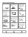
PRECAUTIONS AND REMINDERS
Place unit on even surfaces.
Unplug immediately if is
malfunction like no picture,
no video/audio,smoke and
bad odor from TV.
Don't throw any object
inside the TV box like
metals or other flammable
materials.
Don't place the TV in
confined spaces or in a box
when using it.
Unplug immediately if other
foreign materials are put
inside TV box or if the TV
fell down.
Prohibit/Avoid opening TV
cabinet.
Remember to unplug the
AC cord from the AC outlet
before cleaning. Do not use
liquid cleaners or aerosol
cleaners to clean the display.
Make sure to unplug the
unit when not in use for a
long period of time (days).
Do not cover or block
any vents and openings.
Inadequate ventilation
may shorten the life of
the display unit and cause
overheating.
Avoid direct sunlight, dusty,
high humidity and smoky
areas
.
Call service personnel to
clean the internal part of
the TV once a year.
Do not place the display
near water, such as bathtub,
washbasin, kitchen sink
laundry tub, swimming pool
or in a damp basement.
Notice for Remote Controller
Avoid Dropping
1
2
3
4
5
6
7
8
9
0
Avoid Liquids
1
2
3
4
5
6
7
8
9
0
Avoid Aerosol Cleaners
1
2
3
4
5
6
7
8
9
0

4
IMPORTANT SAFETY INSTRUCTIONS
Read before operating equipment
1. Read these instructions.
2. Keep these instructions.
3. Heed all warnings.
4. Follow all instructions.
5. Do not use this apparatus near water.
6. Clean only with a dry cloth.
7. Do not block any of the ventilation openings. Install in accordance with the manufacturers
instructions.
8. Do not install near any heat sources such as radiators, heat registers, stoves, or other apparatus
(including amplifiers) that produce heat.
9. Do not defeat the safety purpose of the polarized or grounding type plug. A polarized plug has two
blades with one wider than the other. A grounding type plug has two blades and third grounding
prong. The wide blade or third prong is provided for your safety. When the provided plug does not
fit into your outlet, consult an electrician for replacement of the obsolete outlet.
10. Protect the power cord from being walked on or pinched particularly at plugs, convenience
receptacles, and the point where they exit from the apparatus.
11. Only use attachments/accessories specified by the manufacturer.
12. Use only with a cart, stand, tripod, bracket, or table specified by the manufacturer, or sold with the
apparatus. When a cart is used, use caution when moving the cart/apparatus combination to avoid
injury from tip-over.
13. Unplug this apparatus during lightning storms or when unused for long periods of time.
14. Refer all servicing to qualified service personnel. Servicing is required when the apparatus has been
damaged in any way, such as power-supply cord or plug is damaged, liquid has been spilled or objects
have fallen into apparatus, the apparatus has been exposed to rain or moisture, does not operate
normally, or has been dropped.
15. The TV should be operated only from the type of power source indicated on the label. If you are not
sure of the type of power supplied to your home, consult your dealer or local power company.
16. Class I Protective Earthing Connection – "The Class I apparatus shall be connected to a mains socket
outlet with a protective earthing connection."
17. Disconnect Device - Mains Plug or Appliance Coupler – "The mains plug or appliance coupler is
used as the disconnect device, the disconnect device shall remain readily operable."
18. Disconnect Device - An all-pole MAINS SWITCH – "An all-pole MAINS SWITCH is used as the
disconnect device, the switch shall remain readily operable."
19. Service Instructions – "CAUTION – These servicing instructions are for use by qualified service
personnel only. To reduce the risk of electric shock, do not perform any servicing other than that
contained in the operating instructions unless you are qualified to do so."
20. Wall Mount Bracket Wording – "For use only with UL Listed Wall Mount Bracket with minimum
weight/load: Please see page.24"
21. Information about the DTV transition –after June 12,2009, a television receiver with only an analog
broadcast tuner will require a converter box to receive full power over-the- air broadcasts with an
antenna because of the Nation's transition to digital broadcasting. Analog-only TVs should continue
to work as before to receiver low power, Class A or translator television stations and with cable
and satellite TV services, gaming consoles, VCRs, DVD players, and similar products. For more
information about the DTV transition is available from http://www.DTV.gov or 1-888-CALL-FCC,
and from http://www.dtv2009.cov or 1-888-DTV-2009 for information about subsidized coupons for

5
digital-to-analog converter boxes.
CONSUMER ALERT – This television receiver has only an analog broadcast tuner and will require a
converter box after June 12,2009,to receive over-the-air broadcasts with an antenna because of the
Nation's transition to digital broadcasting. Analog-only TVs should continue to work as before with
cable and satellite TV services, gaming consoles, VCRs, DVD players, and similar products, For more
information, call the Federal Communications Commission at 1-888-225-5322(TTY:1-888-835-5322)
or visit the Commission's digital television website at:www.DTV.gov.
22. Tilt/Stability – All televisions must comply with recommended international global safety standards
for tilt and stability properties of its cabinets design.
Do not compromise these design standards by applying excessive pull force to the front, or top,
ƕ
of the cabinet, which could ultimately overturn the product
Also, do not endanger yourself, or children, by placing electronic equipment/toys on the top
ƕ
of the cabinet. Such items could unsuspectingly fall from the top of the set and cause product
damage and/or personal injury.
23. Wall or Ceiling Mounting – The appliance should be mounted to a wall or ceiling only as
recommended by the manufacturer.
24. Power Lines – An outdoor antenna should be located away from power lines.
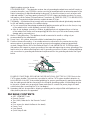
25. Outdoor Antenna Grounding – If an outside antenna is connected to the receiver, be sure the
antenna system is grounded so as to provide some protection against voltage surges and built
up static charges. Section 810 of the National Electric Code, ANSI/NFPA No. 70-1984, provides
information with respect to proper grounding of the mats and supporting structure grounding of the
lead-in wire to an antenna-discharge unit, size of grounding connectors, location of antennadischarge
unit, connection to grounding electrodes and requirements for the grounding electrode. See Figure
below.
ANTENNA
ANTENNA DISCHARGEUNIT
GROUNDING CONDUCTORS
POWER SERVICE GROUNDING ELECTRODE SYSTEM
GROUND CLAMPS
ELECTRICSERVICE EQUIPMENT
GROUND CLAMP
EXAMPLE OF ANTENNA GROUNDING AS PER NATIONAL ELECTRICAL CODE Note to the
CATV system installer: This reminder is provided to call the CATV system installer’s attention to
Article 820-40 of the NEC that provides guidelines for proper grounding and, in particular, specifies
that the cable ground shall be connected to the 6 English grounding system of the building, as close
to the point of cable entry as practical. Please, make sure to connect the power plug to the wall
outlet socket after connecting the TV to the adapter!
26. Apparatus shall not be exposed to dripping or splashing and no objects filled with liquids,such as
vases, shall be placed on the apparatus.
PACKAGE CONTENTS
AOC
ƕ
L32W961 TV unit
Remote Control
ƕ
Two (AAA) Batteries for the Remote Control
ƕ
Base
ƕ
Four screws (to attach the Base to the stand)
ƕ
Power Cord
ƕ
User Manual
ƕ
Quick Setup Guide
ƕ

6
PREPARATION
IMPORTANT: Do not apply pressure to the screen display area which may compromise the
integrity of the display. The manufacturer’s warranty does not cover user abuse or improper
installations.
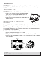
ATTACHING THE BASE
IMPORTANT: The Base of the HDTV must be assembled prior to usage.
1. Place TV unit face down on a soft and flat surface (blanket,
foam, cloth, etc.) to prevent any damage to the HDTV.
2. Carefully align and insert the Base to the stand.
3. Insert the screws to the bottom of the base and tighten the
base to the stand.
PREPARING YOUR LCD HDTV FOR WALL
MOUNTING
We suggest that you keep your TV at least 2.56 inches (65 mm) from the wall to prevent cable
interference.
Before mounting your TV on the wall, you need to remove the base.
For your safety, please use only with UL listed wall mount bracket with minimum weight of the
TV without stand. (Please see page.24.)
To attach a wall mount bracket to your TV:
1 Remove the screws holding your TV to the stand.
2 Pull up the stand base from the hinge to remove the stand base from your TV.
3 Secure the wall mount bracket to the back of your TV using four M6 screws, as indicated
in the illustration.
200 mm
200 mm
NOTE
f 200mmx200mm wall mount bracket & M6 screws are not included.

7
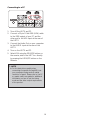
3. Remote control:
Remove the cover of the battery
compartment. Insert the 2 batteries
supplied (Type AAA 1.5V).
4. Power:
Insert the power cord in the wall socket
with AC power supply. You can see LED
states at the front panel. If the LED color
is
Blue
, means the TV set is power on. If
the LED color is Red, which means this TV
set is in standby state.
5. Turn the TV on:
Press the POWER key on the Remote
control or the side panel control knobs.
The TV will be turned on in a minute with
display on the screen.
MUTESOURCE
Power Key
Please make sure to connect the power plug
to the wall outlet socket after connecting the
TV to the power cord!
1. Install the base stand; place the TV
on a solid surface.
Min
1m
Ensure that the TV is placed in a position
to allow free flow of air. Do not cover the
ventilation openings on the back cover.
To prevent any unsafe situations, no naked
flame sources, such as lighted candles,
should be placed on or in the vicinity.
Avoid heat, direct sunlight and exposure
to rain or water. The equipment shall not
be exposed to dripping or splashing.
2. Connect the antenna cable or CATV cable
to the aerial socket ANT IN 75
:
at the
back of the TV set.

8
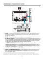
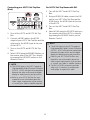
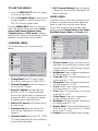
PERIPHERAL CONNECTION GUIDE
3
AC POWER
1. HDMI – Connect the primary source for digital video such as a DVD multimedia player or
set top box through this all digital connector. The white color band on the rear of the TV
indicates this connection.
2. PC IN – Connect the video and audio cables from a computer here.
3. AV IN (AV/S-VIDEO) – Connect the primary source for composite video devices, such as
a VCR or video game. Use the white and red connectors to connect the external audio from
the same source. The signal being carried by the S-Video cable and connector, if connected,
will take priority over the Video RCA connector (yellow connector).
4. COMPONENT (Y/Pb/Pr with Audio L/R) – Connect the primary source for
component video devices such as a DVD Player or set top box here. From left to right, use
red for Pr, blue for Pb, green for Y, red for right audio (R) and white for left audio (L) inputs.
5. ANTENNA/CABLE DIGITAL/ANALOG – Connect to an antenna or digital cable (out-
of-the-wall, not from Cable Box) for Digital TV.*
6. SPDIF (Optical Digital Audio Out) – When a digital audio signal is associated with the
input selected for viewing, the digital audio will be available on this SPDIF connection to
your home theater system.
Once your equipment is connected, use the following procedure to view the input signal:
Press the source button on the remote controller to select the relevant source to view. (ex: Press
COMP button to select “Component” if you have connected a video recorder to Component socket.)

9
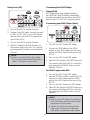
OPERATING INSTRUCTIONS
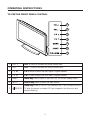
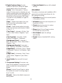
TO USE THE FRONT PANEL CONTROL
1
2
3
5
6
4
7
1 VOL + VOL +: Press to increase the sound volume level.
2. VOL - VOL - : Press to decrease the sound volume level.
3. CH
Ÿ
CH +: Press to select the next higher Program number.
4. CH
ź
CH - : Press to select the next lower Program number.
5. MENU Menu key: Press to open or exit the OSD (on-screen display) menu.
6. INPUT Source key: Press to select the input source.
7.
i
POWER
Power key: Press to turn on / off (standby) the TV set. (Press to turn on
TV after the power on status, LED had changed to the
Blue
color and
stopped flashing.)

10
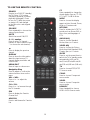
TO USE THE REMOTE CONTROL
POWER
Press to turn ON/OFF (standby)
the TV. (Note: 1.TV is never
completely powered off unless
physically unplugged. 2. Press
to turn on TV after the power
on status, LED had changed
to the Blue color and stopped
flashing.)
SOURCE
Press repeatedly to choose the
various input sources.
MUTE
Switch the sound ON/OFF.
0 ~ 9 /- number
Press to enter TV channel
number to select channel (Press
‘-’ to choose the sub-channel).
Press to display the previous
channel
DISPLAY
Press to show the information
about the input source, TV
channel, display resolution and
current time.
MENU/EXIT
Press to open or close menu.
Navigation Ring
Press to adjust or confirm the
various function items on the
menu
VOL+ / VOL-
Press + or - to adjust the
volume.
CH+ / CH-
Press + or - to browse through
the TV channels.
FAV
Press to display the Favorite
Channel List.
ADD FAV
Press to add channel to Favorite
List
CC
Press repeatedly to change the
closed caption type as CC Off/
CC On/CC On With Mute.
WIDE
Press to choose the display
aspect as: Auto, Normal, Zoom,
Wide, or Cinema mode.
MTS/SAP
Press to activate the NTSC TV
sounds, such as: Stereo, SAP or
Mono tone, and languages of
DTV.
AUDIO ADJ
Press to choose Standard,
Movies, News, or Custom.
VIDEO ADJ
Press to choose the Picture
Mode from Vivid, Standard, PWR,
Theater, Sport, or Custom.
SLEEP
Press to set the preset time to
switch the TV to standby mode
automatically (off/5 min/10
min/15 min/30 min/60 min/90
min/120 min/180 min /240 min).
TV
Press to choose ATSC/NTSC
TV source mode.
COMP
Press to choose Component
source mode.
VIDEO
Press to choose Composite
source mode.
HDMI/PC
Press repeatedly to choose
HDMI or VGA source mode.
MUTE
AUDIO VIDEO
VOL CH
SOURCE
DISPLAY MENU/EXIT
MTS/SAP
HDMI/PCCOMPTV VIDEO
FAV ADD FAV CC WIDE
SLEEP
ADJ ADJ

11
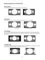
VIEWING MODELS ILLUSTRATIONS
Normal Mode
The original content would be at the center of the screen.
16:9 Content
4:3 Content
Wide Mode
The original content in this mode has to fill the entire screen of the display.
16:9 Content
4:3 Content
ZOOM Mode
For those wide format images which are originally programmed into 4:3 frames with black
bars around, this mode would stretch the image in both width and height for full display with
active data.
Same image in ZOOM mode
CINEMA Mode
This mode is applied to view 2.35:1 format content on 16:9 displays. Cropping on both right
and left sides to keep the image ratio undistorted for users.

12
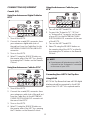
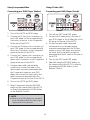
CONNECTING EQUIPMENT
Coaxial (RF)
Using Your Antenna or Digital Cable for
DTV
.
1. Turn off the HDTV.
2. Connect the coaxial (RF) connector from
your antenna or digital cable (out-of-
the-wall, not from the Cable Box) to the
ANTENNA/CABLE DIGITAL/ANALOG
connector.
3. Turn on the HDTV.
4. Select TV using the SOURCE button on
the remote, side of the HDTV or directly
by pressing the TV button on the Remote
Control.
Using Your Antenna or Cable for DTV
.
1. Turn off the HDTV.
2. Connect the coaxial (RF) connector from
your antenna or cable (out-of-the-wall, not
from the Cable Box) to the ANTENNA/
CABLE DIGITAL/ANALOG connector at
the rear of the HDTV
3. Turn on the HDTV.
4. Select TV using the SOURCE button on
the remote, side of the HDTV, or pressing
the TV button on the Remote Control.
Using the Antenna or Cable for your
VCR
1. Turn off the HDTV and VCR.
2. Connect the “Output to TV”, “RF Out”
or “Antenna Out” connector on the rear
of your VCR to the ANTENNA/CABLE
DIGITAL/ANALOG connector at the rear
of the HDTV.
3. Turn on the HDTV and VCR.
4. Select TV using the SOURCE button on
the remote, side of the HDTV or directly
by pressing the TV button on the Remote
Control.
NOTE
f If you have an off-air antenna or cable TV,
connect it to the “Antenna In” connector
on the rear of your VCR.
Connecting Your HDTV Set-Top Box
Using HDMI
HDTV Set-Top Boxes that have a HDMI digital
interface should be connected to the HDMI
input of the LCD HDTV for optimal results.

13
Connecting your HDTV Set-Top Box
(Best)
1. Turn off the HDTV and HDTV Set-Top
Box.
2. Connect a HDMI cable to the HDMI
output of your HDTV Set-Top Box and the
other end to the HDMI Input at the rear
of the HDTV.
3. Turn on the HDTV and HDTV Set-Top
Box.
4. Select HDMI using the
SOURCE button on
the remote, side of the HDTV, or directly
by pressing the HDMI/PC button on the
Remote Control.
NOTE
f
The HDMI input on the HDTV supports
High-bandwidth Digital Content Protection
(HDCP). HDCP encrypts the transmission
between the video source and the digital
display for added security and protection.
f
Refer to your HDTV Set-Top Box user
manual for more information about the
video output requirements of the product
or consult your cable or satellite operator.
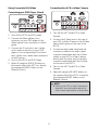
For HDTV Set-Top Boxes with DVI
1. Turn off the HDTV and HDTV Set-Top
Box.
2. Using a HDMI-DVI cable, connect the DVI
end to your HDTV Set-Top Box and the
HDMI end to the HDMI Input at the rear
of the HDTV.
3. Turn on the HDTV and HDTV Set-Top
Box.
4. Select HDMI using the SOURCE button on
the remote, side of the HDTV, or directly
by pressing the HDMI/PC button on the
Remote Control.
NOTE
f
The HDMI input on the HDTV supports
High-bandwidth Digital Content Protection
(HDCP). HDCP encrypts the transmission
between the video source and the digital
display for added security and protection.
f
Refer to your HDTV Set-Top Box user
manual for more information about the
video output requirements of the product
or consult your cable or satellite operator.
f
The DVI to HDMI connection provides
video only. Connection to an alternate
audio player is required for audio.

14
Using Component Video
Connecting your HDTV Set-Top Box
(Better):
1. Turn off the HDTV and HDTV Set-Top
Box.
2. Connect the Pr (red color) connector
on your HDTV Set-Top Box to the
corresponding Pr (red color) connector in
the Component group.
3. Connect the Pb (blue color) connector
on your HDTV Set-Top Box to the
corresponding Pb (blue color) connector
in the Component group.
4. Connect the Y (green color) connector
on your HDTV Set-Top Box to the
corresponding Y (green color) connector
in the Component group.
5. Using an audio cable (red and white
connectors), connect the cable to the
audio output connectors associated with
the Component output on your HDTV
Set-Top Box and connect the other end to
the audio connectors associated with the
Component.
6. Turn on the HDTV and HDTV Set-Top
Box.
7. Select Component using the
SOURCE
button on the remote, side of the HDTV
or directly by pressing the COMP button
on the Remote Control.
NOTE
f
Refer to your HDTV Set-Top Box user
manual for more information about the
video output requirements of the product
or consult your cable or satellite operator.
Connecting Your Basic Set-Top Box
Using Composite Video
1. Turn off the HDTV and Set-Top Box.
2. Using an AV Cable, connect the Video
(yellow color) connector on your Set-Top
Box to the corresponding Video (yellow
color) connector in the AV group at the
rear of the HDTV.
3. Using the red and white connectors,
connect the cable to the audio output
connectors associated with the Video
output on your Set-Top Box and connect
the other end to the audio connectors
associated with the AV input at the rear of
the HDTV.
4. Turn on the HDTV and Set-Top Box.
5. Select AV using the
SOURCE button on
the remote, side of the HDTV or directly
by pressing the VIDEO button on the
Remote Control.

15
Using Coax (RF)
1. Turn off the HDTV and Set-Top Box.
2. Using a Coax (RF) cable, connect one end
to the TV OUT (RF) on your Set Top Box
and the other end to the TV input at the
rear of the HDTV.
3. Turn on the HDTV and Set-Top Box.
4. Select TV using the SOURCE button on
the remote, side of the HDTV or directly
by pressing the TV button on the Remote
Control.
NOTE
f
Refer to your Set Top Box user manual
for more information about selecting the
video or RF output of the product.
Connecting Your DVD Player
Using HDMI
DVD players that have a digital interface
such as HDMI (High Definition Multimedia
Interface) should be connected to the HDMI
input of the LCD HDTV for optimal results.
Connecting your DVD Player (Best)
1. Turn off the HDTV and DVD player.
2. Connect a HDMI cable to the HDMI
output of your DVD player and the other
end to the HDMI Input at the rear of the
HDTV.
3. Turn on the HDTV and DVD player.
4. Select HDMI using the SOURCE button on
the remote, side of the HDTV or directly
by pressing the HDMI/PC button on the
Remote Control.
For DVD Players with DVI:
1. Turn off the HDTV and DVD player.
2. Using a HDMI-DVI cable, connect the DVI
end to your DVD player and the HDMI
end to the HDMI Input at the rear of the
HDTV.
3. Turn on the HDTV and your DVD player.
4. Select HDMI using the SOURCE button on
the remote, side of the HDTV, or directly
by pressing the HDMI/PC button on the
Remote.
NOTE
f
Refer to your DVD player user manual for
more information about the video output
requirements of the product.
f
The DVI to HDMI connection provides
video only. Connection to an alternate
audio player is required for audio output.

16
Using Component Video
Connecting your DVD Player (Better)
1. Turn off the HDTV and DVD player.
2. Connect the Pr (red color) connector on
your DVD player to the corresponding Pr
(red color) connector in the Component
at the rear of the HDTV.
3. Connect the Pb (blue color) connector on
your DVD player to the corresponding Pb
(blue color) connector in the Component
group at the rear of the HDTV.
4. Connect the Y (green color) connector on
your DVD player to the corresponding Y
(green color) connector in the Component
group at the rear of the HDTV.
5. Using an audio cable (red and white
connectors), connect the cable to the
audio output connectors associated with
the Component output on your DVD
player and connect the other end to the
audio connectors associated with the
Component input at the rear of the HDTV.
6. Turn on the HDTV and DVD player.
7. Select Component using the SOURCE
button on the remote, side of the HDTV
or directly by pressing the COMP button
on the Remote Control.
NOTE
f
Refer to your DVD player user manual for
more information about the video output
requirements of the product.
Using S-Video (AV)
Connecting your DVD Player (Good):
1. Turn off the HDTV and DVD player.
2. Connect the S-Video jack on the rear of
your DVD player to the S-Video jack in the
AV group on the rear of the HDTV.
3. Connect an audio cable (white and
red connectors) to the audio output
connectors associated with the S-Video
output on your DVD player and connect
the other end to the audio connectors
associated with the AV input on the rear of
the HDTV.
4. Turn on the HDTV and DVD player.
5. Select AV using the SOURCE button on
the remote, side of the HDTV, or directly
by pressing the VIDEO button on the
Remote Control.

17
Using Composite (AV) Video
Connecting your DVD Player (Good)
1. Turn off the HDTV and DVD player.
2. Connect the Video (yellow color)
connector on your DVD player to the
Video (yellow color) connector in the AV
group.
3. Connect the R (red color) and L (white
color) audio connectors on your DVD
player to the corresponding R (red color)
and L (white color) audio input connectors
in the AV group.
4. Turn on the HDTV and DVD Player.
5. Select AV using the SOURCE button on
the remote, side of the HDTV or directly
by pressing the VIDEO button on the
Remote Control.
Connecting Your VCR or Video Camera
1. Turn off the HDTV and VCR or Video
Camera.
2. Connect the S-Video jack on the rear of
your VCR or Video Camera to the S-Video
jack in the AV group on the rear of the
HDTV.
3. Connect an audio cable (white and red
connectors) cable to the audio output
connectors associated with the S-Video
output on your VCR or Video Camera
and connect the other end to the audio
connectors associated with the AV input
on the rear of the HDTV.
4. Turn on the HDTV and VCR or Video
Camera.
5. Select AV using the SOURCE button on
the remote, side of the HDTV or directly
by pressing the VIDEO button on the
Remote Control.
NOTE
f
Refer to your VCR or Video Camera user
manual for more information about the
video output requirements of the product.

18
Connecting to a PC
1. Turn off the HDTV and PC.
2. Connect a 15-pin D-Sub RGB (VGA) cable
to the RGB output of your PC and the
other end to the VGA input at the rear of
the HDTV.
3. Connect the Audio Out on your computer
to the AUDIO input at the rear of the
HDTV.
4. Turn on the HDTV and PC.
5. Select VGA using the SOURCE button on
the remote, side of the HDTV or directly
by pressing the HDMI/PC button on the
Remote.
NOTE
f
For the best picture quality when
connecting a computer through VGA, set
your computer timing mode to native
resolution of panel. Please refer to the PC
or graphic card’s user guide for additional
information on how to set the timing
mode and the video output requirements
of the product.
Page is loading ...
Page is loading ...
Page is loading ...
Page is loading ...
Page is loading ...
Page is loading ...
Page is loading ...
Page is loading ...
Page is loading ...
-
 1
1
-
 2
2
-
 3
3
-
 4
4
-
 5
5
-
 6
6
-
 7
7
-
 8
8
-
 9
9
-
 10
10
-
 11
11
-
 12
12
-
 13
13
-
 14
14
-
 15
15
-
 16
16
-
 17
17
-
 18
18
-
 19
19
-
 20
20
-
 21
21
-
 22
22
-
 23
23
-
 24
24
-
 25
25
-
 26
26
-
 27
27
-
 28
28
-
 29
29


Ask a question and I''ll find the answer in the document
Finding information in a document is now easier with AI
Related papers
-
AOC Flat Panel Television L32W861 User manual
-
-
AOC Flat Panel Television L42H861 User manual
-
AOC L42H831 User manual
-
AOC L19W761 User manual
-
AOC L37W861 User manual
-
-
AOC Flat Panel Television L22W861 User manual
-
Envision L26W661 User manual
-
Other documents
-
Sanyo AVL-279 User manual
-
CyberHome CH-DVD 300 User guide
-
-
-
Westinghouse TX-42F970Z User manual
-
Polaroid TLA-01901C - 19" LCD TV User manual
-
-
Haier LE42D2380 User manual
-
Voyager JE1914DVDC User manual
-
Voyager JTV1917DVDC User manual