Page is loading ...

PICASSO COMPONENT SYSTEM
OWNERS MANUAL/INSTALL GUIDE
www.SOUNDSTREAM.com
Keep in a safe and dry place for future reference.
Model Number of your woofer
Serial Number
Place of purchase
Notes
Soundstream Technologies
1550 S. Maple Ave.
Montebello, CA 90640 USA
PH: 323.724.4600 FX: 323.722.8125
www.soundstream.com

Congratulations on your purchase of Soundstream’s Picasso component
speaker system. The Picasso component system represents Soundstream’s
design approach to creating musical reproduction with the richness and
clarity while maintaining cost effectiveness. Only the best materials and
production techniques were used to create an exceptional line of
component system speakers. We hope you will enjoy your Picasso
components for many years to come.
Features:
• Stamped steel basket with brushed finish
• Woven glass fiber spruce pulp laminate cone
• NBR rubber surround
• Precision machined and matched motor assembly
• Custom embossed protective magnet boot
• 1” Copper voice coil on aluminum former with reinforced neck joint
• 1” Teflon silk dome tweeter with resin coating
• DC tweeter protection circuit
• 12dB low pass with presence switch
• 18dB high pass with 3-way sensitivity switch
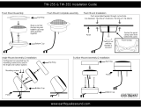
Tweeter Installation
Mounting hardware contained in the packaging will allow a surface or flush
mount installation. The tweeter should be mounted on the same plane and
within 6 inches of the mid-bass driver to avoid any phase shift. Also, as the
frequencies that the tweeter reproduces are very directional, avoid placing
the tweeter in a position that will be obstructed either by objects in the vehicle
or by passengers. As with the mid-bass driver, if a factory tweeter location is
available, it is recommended that it be used. If it is necessary to cut a hole to
mount the tweeter, then be careful to find a location that will have enough
depth and will not interfere with any moving parts in the vehicle.
Flush Mounting: When flush mounting the tweeter, it will be necessary to use
the tweeter cup, rear wing bracket. Mount the rear wing bracket to the
mounting cup with the supplied screw, insert the tweeter into the cup and
secure with the same screw used to mount the wing bracket. Push the tweeter
assembly into the rear of the vehicle’s tweeter opening and fasten assembly
to the opening by twisting on the flush mount ring from the front.

Impedance 4 ohms
Freq.Response 50Hz - 20KHz
Sensitivity 89dB
Power Watts (Rms/Peak) 50Watts/100Watts
Specifications
Dimensions
Mid-bass Installation
• Determine the mounting location. Factory speaker locations are
recommended for ease of installation. When installing in the factory
speaker locations, make sure that there is enough depth to
accommodate the replacement speaker.
• If an alternate locations is used, measurements should be carefully
taken before any cutting is done to insure that there is enough depth
and to make sure that the speaker will not interfere with any moving
parts in the vehicle (i.e. window gears/braces, hood/trunk cables, etc.).
Once the mounting location is decided upon, the grill-mounting ring
can be used as a template to mark the hole and screw locations. If the
panel that the speaker is to be mounted to can be removed, then it is
recommended that the panel be removed before cutting the speaker
hole. Once the hole is cut to fit the speaker, replace the panel. If there
is any metal obstruction the installation of the speaker, with top panel in
place, mark the metal that needs to be removed and then remove it
with tin snips or a saw.
• The wiring that is used should be at least 18 gauge to avoid possible
signal loss. High quality crimp style connectors should be used to
connect the wires to the speaker. Soldering wires directly to the speaker
will void the warranty. If new wiring is necessary, make sure the route
the wires under factory moldings to make the installation as neat as
possible. In addition, make sure that the new wiring is clear of any screw
or clip holes so that it will not be pinched or shorted to metal after
factory panels and screws are replaced.

Crossover Installation
1. The crossover should be mounted in a dry, moisture free location. Never
install the crossover in the door where it can be damaged by water and
moisture. The crossover can be installed in the door panel as long as there
is an undamaged vapor barrier.
2. There are three sets of connections on the crossover. The Input terminals
should be connected to the source of the signal (radio or amplifier). The
woofer terminals should be connected to the midbass driver. The tweeter
terminals should be connected to the tweeter. The tweeter volume can be
set at -3dB, 0dB and +3dB. Ensure that the negative polarity wire of the
tweeter is the one used for setting the tweeter volume level. Make sure
that the polarity on all connections is correct.
L1
L2
C1
C2
C3
R1
R2
R3
R4
+3dB0dB
-3dB
TW+ WF- WF+
PUT-
+IN
/