Page is loading ...

®
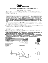
Professional UHF Wireless Microphone System
VM-82U
Operating Instructions
Passionate about Music
www.BetterMusicBuilder.com
Thank you for purchasing this unit. To
make full and effective use of this unit,
please read this Owner's Manual
carefully before operating it. Please
retain this manual for future reference.
UHF
UHF WIRELESS SYSTEM
VM-82UH
Better Music Builder
®
POWER
RF
AF
CHAN.
5 10 15 20 25 30 35 40
-30 -25 -20 -15 -10 -5 0 PEAK
CH 002
MUTE
RF
AF
CHAN.
5 10 15 20 25 30 35 40
-30 -25 -20 -15 -10 -5 0 PEAK
CH 004
MUTE
SET SET
Better Music Builder
®
ANTENNA-BVOLUME
DUAL CHANNEL RECEIVER VM-82U
RECEIVER - A LCDANTENNA-A VOLUME RECEIVER - B LCD
64 SELECTABLE WIRELESS SYSTEM
UHF

2
CONTENTS
INTRODUCTION................................................................................................................................................... 3
SYSTEM CHARACTERISTICS.......................................................................................................................... 3
RECEIVER DESCRIPTION.................................................................................................................................. 4
RECEIVER LCD PANEL DESCRIPTION............................................................................................. 5~7
RECEIVER & HANDHELD TRANSMITTER LCD DISPLAY DESCRIPTION..................... 7
THE SYSTEM INCLUDES THE FOLLOWING PARTS................................................................... 8
SETTING UP YOUR RECEIVER..................................................................................................................... 8
CHANNEL OPERATION............................................................................................................................ 8~9
RECEIVER dB SETUP........................................................................................................................................... 10
HAND-HELD TRANSMITTER dB SETUP............................................................................................. 11
RECEIVER SIGNAL INTERFERENCE 1.................................................................................................... 12
RECEIVER SIGNAL INTERFERENCE 2.................................................................................................... 13
HOW TO ADJUST RECEIVER SETTINGS........................................................................................... 14
HOW TO CONNECT AUDIO OUT..................................................................................................... 15
UHF WIRELESS SYSTEM DIAGRAM........................................................................................................ 15
DC-POWER CONNECTION...................................................................................................................... 16
OPTIONAL: 19” RACK MOUNT KIT...................................................................................................... 16
VM-82UH HAND-HELD TRANSMITTER DESCRIPTION..................................................... 17
HAND-HELD TRANSMITTER LCD PANEL DESCRIPTION.......................................... 18~20
HOW TO INSERT HAND-HELD TRANSMITTER’S BATTERIES.......................................... 21
HOW TO TURN ON AND OFF HAND-HELD TRANSMITTER........................................ 22
HOW TO SET UP YOUR HAND-HELD TRANSMITTER............................................... 23~25
VM-82UB BODY-PACK TRANSMITTER SYSTEM SPECIFICATION............................... 26
BODY-PACK TRANSMITTER LCD PANEL DESCRIPTION............................................27~28
HOW TO INSERT BODY-PACK TRANSMITTER BATTERIES............................................... 29
HOW TO WEAR BODY-PACK TRANSMITTER............................................................................ 30
HOW TO SET UP YOUR BODY-PACK TRANSMITTER.......................................................... 30
TECHNICAL FEATURES.................................................................................................................................. 31
THE SYSTEM INCLUDES THE FOLLOWING PARTS................................................................. 31
VM-82U FCC FREQUENCY (GROUP A)......................................................................................... 32
VM-82U FCC FREQUENCY (GROUP B)......................................................................................... 33
FREQUENCIES AVAILABLE FOR USE: Receiver (Group A)............................................ 34~36
FREQUENCIES AVAILABLE FOR USE: Receiver (Group B)............................................ 37~39
FREQUENCIES AVAILABLE FOR USE: Hand-held Transmitter..................................... 40~41
FREQUENCIES AVAILABLE FOR USE: Body-pack Transmitter..................................... 42~44
FREQUENCY SCAN GROUPS FOR BAND C & BAND D...................................................... 45
US UHF WIRELESS OPERATING FREQUENCIES................................................................. 46~47
TROUBLESHOOTING.............................................................................................................................48~49
PRECAUTION........................................................................................................................................................ 50
MAINTENANCE................................................................................................................................................... 51

3
INTRODUCTION
As a leader in the Karaoke market, the engineering team of Better Music Builder
recently designed the VM-82U UHF Wireless microphone system. VM-82U has
two different frequency groups. Group A has 32 different frequencies and Group
B has 1,280 different frequencies, which are authorized for use in United States
by FCC.
One of the outstanding features of VM-82U is that it allows individual and group
singing as well as playing with musical instruments. Our engineering team designs
this unit in such a way that the sensitivity can be adjusted at the transmitter
(hand-held microphone) for singing and playing musical instruments. Therefore, a
high sensitivity is good for playing musical instrument because it can pick up
signals from the musical instrument for high performance. On the other hand, a
low sensitivity is good for singing because it can reduce the noise when holding
the hand-held microphone.
In addition, the dual channel function of the receiver in this unit allows two
microphones to operate at the same time. Therefore, this special feature is good
for duet singing. This single unit is equivalent to two units for the same function
by other brands.
This wireless system may operate on some UHF frequencies that are not
authorized in your area. Please contact the relevant governmental department in
your country to obtain information on the authorized UHF frequencies for the
wireless system in your area.
SYSTEM CHARACTERISTICS
1. Equipped with the latest wireless technology and UHF dual-channel with one
receiver to picks up weak signals and prevents signal interference.
2. Clear LCD screen that can allow you to check AF (Audio Frequency) and RF
(Radio Frequency) signal levels.
3. Receiver Sensitivity can be adjustable from 0 dB to 40 dB for different
environmental conditions.
4. Hand-Held microphone Sensitivity can be adjustable from 0dB to -30dB for
different environmental conditions. For example, -20dB is good for singing
while 0dB (the highest sensitivity) is good for playing muscial instrument.
5. One receiver has two built-in units (Receiver A and Receiver B).
6. Audio signal can cover a distance from 10 feet to 300 feet.
7. Easy and convenient mounting for portable rack.
8. Adjustable antennas for different angles to receive better signals.

MODEL: VM-82U (UHF Microphone)
CALIFO RNIA, U NITED STATES OF AM ERICA
COMMEN TS? inf o@bettermusi cbuild er.com
www.Be tterMus icBuilder.co m
ENGINE ERED AN D DESIGN IN U.S.A.
FCC: 74.861
SERIAL:
Better Music Builder
®
RIS K OF ELECT RIC S HOCK
DO NOT O PEN
Tak ing a part or mo difyin g the
rec eiver may lead to el ectri c sho ck,
fir e, or dama ge to the recei ver a nd
wil l voi d your warr anty.
BALANC EDUNBALA NC ED
OUTPUT
CHANNEL B
UNBALA NC ED
A & B
CHANNEL OU TPU T
BALANC ED UNBALA NC ED
OUTPUT
CHANNEL ADC-POWER
DC12~1 6V
RF
AF
CHAN.
5 10 15 20 25 30 35 40
-30 -25 -20 -15 -10 -5 0 PEAK
CH 001
MUTE
SET
ANTENNA-BVOLUME
DUAL CHANNEL RECEIVER VM-82U
SET
RECEIVER - A LCDAN TE NN A- A VO LU ME
RF
AF
CHAN.
5 10 15 20 25 30 35 40
-30 -25 -20 -15 -10 -5 0 PEAK
CH 002
MUTE
RECEIVER - B LCD
64 SELECTABLE WIRELESS SYSTEM
UHF
POW ER
Better Music Builder
®
4
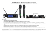
RECEIVER DESCRIPTION
NAMES & FUNCTION:
Front Panel:
1. Receiver Antenna input-A. (Channel-A) BNC socket.
2. Receiver A Volume control (Channel-A).
3. Receiver A LCD Display.
4. Press “
▲
” UP or “
▼
” DOWN to set a specific frequency for Channel-A.
5. Power button On/Off (Press and hold the power button for 3 seconds until
the LCD screen lights turn on/off).
6. Press “
▲
” UP or “
▼
” DOWN to set a specific frequency for Channel-B.
7. Receiver B LCD Display.
8. Receiver B Volume control (Channel-B).
9. Receiver Antenna input-B. (Channel-B) BNC socket.
Rear Panel:
10. Channel-B 1/4-inch unbalanced audio output connector.
11. Channel-B XLR 3M socket balance audio output 50Hz~15KHz +/-3dB.
12. Channel A & B 1/4-inch (6.3 mm) jack socket unbalanced audio output,
mixed channel A & B.
13. Power supply dock with removable IEC cable 12~16V.
14. Channel-A XLR 3M socket balance audio output 50Hz~15KHz +/-3dB.
15. Channel-A 1/4-inch unbalanced audio output connector.
1 92 853 74 6
10 1511 1412 13

5
RECEIVER LCD PANEL DESCRIPTION
After turning on the “POWER” button, LCD screen will light up as
below:
1. RF (radio frequency) Indicator
2. AF (audio frequency) Indicator
3. Current Channel/Frequency Display: current value depends on your setting.
If there is static or no sound coming out of your speakers, than
there may be a frequency interruption from another system, change your
frequency to match your transmitter’s (microphone) frequency.
4. Mute Indicator: When “MUTE” is displayed, this means that there is no vocal
signal(s) going out. When the microphone is on, “MUTE” would not appear.
5. This unit is in Diversity signal indicator. Either “I” or “II” would appear at the
lower hand corner of the screen.
SENSITIVITY ADJUSTMENT (SQELCH) PROGRAMMING:
1. Keep pressing “SET” until LCD screen
indicates “SQELCH” as shown on the left.
If the microphone is off, but all RF
indicators show signals, it means that you
need to change to different frequency.
2. After 2 to 3 seconds, the screen will
display your current dB settings.
When setting the dB in the receiver,
it has a different function from that of the
transmitter (hand-held microphone). The dB
in the receiver is for distance coverage while
the dB in the transmitter is for sensitivity.
This menu is for adjusting sensitivity, and to
prevent signal interference. The range of
adjustment is 0~40dB. The recommended
value is 20dB. (Manufacture default setting).
The lower the dB the farther away you can
be, but the more interference.
4
5
3
1
2
NOTE
NOTE
NOTE
Range
328 feet
292 feet
256 feet
220 feet
184 feet
148 feet
112 feet
75 feet
39 feet
100 m
89 m
78 m
67 m
56 m
45 m
34 m
23 m
12 m
Display
00 dB
05 dB
10 dB
15 dB
20 dB
25 dB
30 dB
35 dB
40 dB
Receiver Distance Coverage
Press “
▲
” UP or “
▼
” DOWN to select a different value the LCD screen will
flash. Press “SET” to confirm your adjustments. If you haven’t pressed “SET”, no
change will be made and the LCD screen will keep flashing.

1. Keep pressing “SET” until LCD screen
indicates “DISPL” as shown on the left.
2. After 2 to 3 seconds, the LCD screen will
appear as the figure on the left.
Manufacturer has set up four (4)
channels (frequencies) for easy operation.
The Receiver A and Receiver B has different
frequencies. Although Receiver A and
Receiver B each has four channels, the
frequencies are different.
6
CHANNEL/FREQUENCY PROGRAMMING:
NOTE
This menu’s function is for switching your frequency displays between actual
frequency or channel. LCD indicates the two modes, "CHANNL" (channel) or
FREQU” (frequency).
Press “
▲
” UP or “
▼
” DOWN to select a different value the LCD screen will
flash. Press “SET” to confirm your adjustments. If you haven’t pressed “SET”, no
change will be made and the LCD screen will keep flashing.
1. Keep pressing “SET” until LCD screen
indicates “TUNE” as shown left.
2. After 2 to 3 seconds, the screen will
display your current frequency settings.
This menu indicates the present receiver’s
working CHANNEL/FREQUENCY signal.
Tuning of the frequencies is made in 25MHz
steps.
Press “
▲
” UP or “
▼
” DOWN to select the
present signal channel/frequency the LCD
screen will flash. Press “SET” to confirm your
adjustments. If you haven’t pressed “SET”, no
change will be made and the LCD screen will
keep flashing.
TUNING CHANNEL/FREQUENCY PROGRAMMING:

7
1. Keep pressing “SET” until LCD screen
indicates “LOCK” as shown on the left.
2. After 2 to 3 seconds, the LCD screen will
appear as the figure on the left.
The screen depends on your current
display settings.
This menu’s function is to lock/unlock your
system’s settings. If it is in the locked “LOC
ON” status, you can’t change any your
current settings or power off. If it is unlocked
“LOCOFF” you can change any settings.
Press “
▲
” UP or “
▼
” DOWN to select a
different value the LCD screen will flash.
Press “SET” to confirm your adjustments. If
you haven’t pressed “SET”, no change will be
made and the LCD screen will keep flashing.
NOTE
SYSTEM LOCK PROGRAMMING:
RECEIVER & HANDHELD TRANSMITTER LCD
DISPLAY DESCRIPTION
Receiver
Channel 1
SQ Adjusting
Display
Channel Display
Frequency Display
Tune
Lock
Lock On
Lock Off
Off
Transmitter
Channel 1
Sensitivity Adjusting
Display
Channel Display
Frequency Display
Tune
Lock On
Lock Off
Low Battery
Battery
Display
BAT

8
THE SYSTEM INCLUDES THE FOLLOWING PARTS
The package comes with one receiver, two transmitters, one DC power adapter,
one plastic screw driver, one audio cable, four AA batteries, and two antennas.
SETTING UP YOUR RECEIVER
1. Screw the antennas (BNC socket) into the front panel of the receiver in a vertical
90° angle and turn it in clockwise to lock it.
You can adjust the antennas to angle differently for adjusting signal strengths.
2. Insert the DC adapter into the power socket of the rear panel the power
supply must comply the requirement of the system.
3. To turn on, turn Volume to the minimum. Press and hold the power button
for 3 seconds until the LCD screen lights turn on.
4. Adjust the settings to your liking (See the description for the LCD or control panel).
5. To turn off, press and hold the power button for 3 seconds until the power
stop. LCD screen will display “OFF”, then power will automatically shut off.
CHANNEL OPERATION
This unit has dual channel operation (Receiver A and Receiver B). It has 1,280 different
frequencies. For easy operation, our manufacturer designs this unit in such a way that
each receiver (Receiver A and Receiver B) has four different frequencies. Therefore, it
has a total of eight different frequencies from both Receiver A and Receiver B. With
this special feature, you can use the same channel with your microphones.
DC Power
Adapter: 1 Unit
Audio Cable (For mixed out): 1 Unit
AA
ALKALINE
BATTERY
AA
ALKALINE
BATTERY
AA
ALKALINE
BATTERY
AA
ALKALINE
BATTERY
AA (1.5V) Battery: 4 Units
Receiving Antenna:
2 Units
Hand-held Transmitter: 2 Units
6.5 inches
16.5 cm
Plastic Screw Driver
Receiver: 1 Set
RF
AF
CHAN.
5 10 15 20 25 30 35 40
-30 -25 -20 -15 -10 -5 0 PEAK
CH 001
MUTE
SET
ANTENNA-BVOLUME
DUAL CHANNEL RECEIVER VM-82U
SET
RECEIVER - A LCDAN TE NN A- A VO LU ME
RF
AF
CHAN.
5 10 15 20 25 30 35 40
-30 -25 -20 -15 -10 -5 0 PEAK
CH 002
MUTE
RECEIVER - B LCD
64 SELECTABLE WIRELESS SYSTEM
UHF
POW ER
Better Music Builder
®
UHF
UHF W IRELESS S YSTEM VM -82U
Better Music Builder
®

9
Channel-1
Channel-3
Channel-4
Channel-1
Channel-2
Channel-3
Channel-4
RECEIVER CHANNEL A (Left) RECEIVER CHANNEL B (Right)
Figure 1
RECEIVER - B LCD
Figure 5
Figure 3
RECEIVER - A LCD
Figure 4
Once the receiver is on, the RF and AF
would appear in the LCD screens.
Channel A (Left) and Channel B (Right)
have different frequencies.
When the receiver is on, but the
transmitter is off, it is normal that there is
no RF signal. If there is RF signal, there is
interference, change the frequency.
If “BAT” appears with strong signal, it
means that there is enough battery. If the
bar has less than two units, you need to
change the battery.
When the transmitter (i.e. hand-held
microphone or body pack) is not on, but
the receiver LCD screens show RF, it
means that there is interference, so you
need to change the channel.
Figure 7
When the microphone is on, “MUTE”
would not appear on the LCD screen.
Either “I” or “II” would blink at the lower
right hand corner because the unit is in
diversity.
If “BAT” appears with weak signal, it
means that there is not enough battery.
If the bar has less than two units, you
need to change the battery.
Figure 8
RECEIVER - B LCD
Figure 6
When the transmitter (i.e hand-held
microphone or body pack) is on, and the
RF signal is weak, then you should change
to different channels or frequencies.
HAND-HELD TRANSMITTER
Channel-2
Figure 2
When the microphone is off and the
receiver is on, there are no RF and AF
signals as indicated in the diagram. This
is normal.
RECEIVER - A LCD
HAND-HELD TRANSMITTER
RECEIVER - B LCD
RECEIVER - A LCD
HAND-HELD TRANSMITTER
HANDHELD TRANSMITTER
HAND-HELD TRANSMITTER
RECEIVER - A LCD
HAND-HELD TRANSMITTER HAND-HELD TRANSMITTER
HANDHELD TRANSMITTER
BAT
CHANNEL OPERATION
RECEIVER - B LCD

10
RECEIVER dB SETUP
UHF-SERIES
SETGAIN
HI
POWER
LO
VM-82UB
Body-Pack
VM-82UH
Transmitter
VM-82U Receiver
00 dB
Distance Coverage
100 m
328 ft
OR
UHF-SERIES
SETGAIN
HI
POWER
LO
VM-82UB
Body-Pack
VM-82UH
Transmitter
VM-82U Receiver
15 dB
67 m
220 ft
OR
UHF-SERIES
SETGAIN
HI
POWER
LO
VM-82UB
Body-Pack
VM-82UH
Transmitter
VM-82U Receiver
30 dB
34 m
112 ft
OR
UHF-SERIES
SETGAIN
HI
POWER
LO
VM-82UB
Body-Pack
VM-82UH
Transmitter
VM-82U Receiver
05 dB
Distance Coverage
89 m
292 ft
OR
UHF-SERIES
SETGAIN
HI
POWER
LO
VM-82UB
Body-Pack
VM-82UH
Transmitter
VM-82U Receiver
20 dB
56 m
184 ft
OR
UHF-SERIES
SETGAIN
HI
POWER
LO
VM-82UB
Body-Pack
VM-82UH
Transmitter
VM-82U Receiver
35 dB
23 m
75 ft
OR
78 m
256 ft
UHF-SERIES
SETGAIN
HI
POWER
LO
VM-82UB
Body-Pack
VM-82UH
Transmitter
VM-82U Receiver
10 dB
Distance Coverage
OR
45 m
148 ft
UHF-SERIES
SETGAIN
HI
POWER
LO
VM-82UB
Body-Pack
VM-82UH
Transmitter
VM-82U Receiver
25 dB
OR
12 m
39 ft
UHF-SERIES
SETGAIN
HI
POWER
LO
VM-82UB
Body-Pack
VM-82UH
Transmitter
VM-82U Receiver
40 dB
OR
The dB setup of receiver is to cover the distance range. The dB setup of
receiver has different functions than that of the hand-held microphone. The dB
setup of hand-held microphone is to adjust the sensitivity.
NOTE

11
Figure 2: Group Singing
BAT
Figure 1: Single Person Singing
BAT
3 inches
For single person use, we
recommend setting the receiver to
the minimum 30 dB because the
hand-held microphone would be
less sensitive.
For musical instruments, we
recommend setting the hand-held
microphone to 0 dB because it
would pick up full quality sound of
the musical instruments.
For group use, we recommend
setting the hand-held microphone
to -10 dB.
The dB setup of hand-held
microphone is to adjust the
sensitivity. The dB setup of receiver
has different functions than that of
the hand-held microphone. The dB
setup of receiver is to cover the
distance range.
NOTE
HAND-HELD TRANSMITTER dB SETUP
Figure 3: Musical Instruments
Range
Maximum Sensitivity
Average
Manufacturer default
Minimum Sensitivity
Display
0 dB
-10 dB
-20 dB
-30 dB
Transmitter Sensitivity

0dB
Volume
CENTER
5-CHANNEL POWER AMPLIFIER
POWER
OFF ON
Better Music Builder
®
TM
DX-1500 Pro
0dB
Volume
Channel-A
Main Left
LIGHT
CUP
SIGNAL
POWER
0dB
Volume
Channel-B
Main Right
LIGHT
CUP
SIGNAL
POWER
0dB
Volume
Channel-C
Rear Left
LIGHT
CUP
SIGNAL
POWER
0dB
Volume
Channel-D
Rear Right
LIGHT
CUP
SIGNAL
POWER
MIC . V OL UME
VOLMIC ROP HO NE TO NE
MIC. INPUT
MIC 1 MIC 2
EXCITER
VOLHIGH SUB FREQ
Hz
MIC 1 3 MIC 2 4 LOW REAR
TREBLE
MID
BASS
MOD E A DJ UST AB LE
CENTER
MUSIC VOL
20 240
VOL
EXCITER MIC AUDIO SUB INPUT
SR
UP
DOWN
MEMORY
5 CHANNEL AUDIO VIDEO EFFECTS PROCESSOR
MUSIC VOL 10
CDG DVD VOD
TM
Better Music Builder
®
DX-5000
POWER
MUSIC L OCK
MIC MAS TER V OLUME MUSIC V OLUME
CENTERECHO
TREBLE
POST
ECHO VO LUME
POWE R
MICROPH ONE G AIN MICROPH ONE I NPUT
VOL
MUSIC T ONE
SUB VOLMONITOR
MUSIC V OL
MONITOR
MIC VOL
SUB FRE Q
REPEAT
MUSIC
MUTE
MIC
EXCITER
MIC A UDIO INP UT
SELECT
MODE
MIC 1 MIC 3MIC 2
Hz
20 240
BASS TREBLEDELAY BASSREPEAT MID MIC 3MIC 2/5MIC 1/4TREBLE
MIN MAX M AXMIN MAXMIN
MICROPH ONE A DJUST MENT
Passionate about Music
CPU INTEGRATED POWER KARAOKE AMPLIFIER DX-288
Better Music Builder
®
MODE
DIGI TAL P ROC ES S S TE REO P OW ER KAR AO KE AM PLI FI ER
24 B IT 48 KHz S AMP LI NG RA TE DI GITAL PROC ESSOR
UP
DOWN
SR
MIC EFFE CT
1 STEREO
2 ECHO
3 MIX
4 FIX
AUDIO
DSP OFF
DSP 1
DSP 2
loading...
12
SPEAKER SPEAKERPLASMA TV
100 m
328 ft
RECEIVER SIGNAL INTERFERENCE 1
When you set the receiver to 00 dB, it can cover up to 328 feet (100 meters).
However, there may be interference from other wireless devices. For indoor
use, set the receiver at 35 dB or 40 dB.
Figure 1
For equipment rental setup,
make sure that distance
between the microphone
receiver and hand-held
microphone is appropriate.
Please refer to the table
“Receiver Distance
Coverage” on page 13.
NOTE

13
RECEIVER SIGNAL INTERFERENCE 2
For indoor use, we recommend setting the Receiver A and B at 35 dB or 40 dB
to reduce the interference.
Figure 2
MAIN LEFT SPEAKER MAIN RIGHT SPEAKER
PLASMA TV
12 m
39 ft
Wireless
Receiver
Transmitter
Please refer to the next table for receiver dB
setup to achieve the best performance. The
sound performance has nothing to do with
the coverage distance. For example, 00 dB
may produce the most interference because
of a distance over 300 feet. If the receiver is
set at 30 dB, it would cover a distance of 100
feet with less interference. It depends on
your need for sound performance.
NOTE
Range
328 feet
292 feet
256 feet
220 feet
184 feet
148 feet
112 feet
75 feet
39 feet
100 m
89 m
78 m
67 m
56 m
45 m
34 m
23 m
12 m
Display
00 dB
05 dB
10 dB
15 dB
20 dB
25 dB
30 dB
35 dB
40 dB
Receiver Distance Coverage

14
HOW TO ADJUST RECEIVER SETTINGS
Press “SET” to select a setting mode for your receiver. (Refer to
pages 5~7 for more information).
To adjust your receiver’s channel/frequency by pressing the “
▲
” UP
or “
▼
” DOWN button to select your frequency.
Turn “VOLUME” button to adjust your vocal volume.
We recommend setting the volume to the maximum, then control it
from the mixer.
If you or anyone do any damage on any part of the receiver either
accidentally or intentionally, we have the right to void your warranty.
VOLUME
SET
RF
AF
CHAN.
5 10 15 20 25 30 35 40
-30 -25 -20 -15 -10 -5 0 PEAK
MUTE
CHANNEL- B LCD
64 SELECTABLE WIRELESS SYSTEM
UHF
VOLUME
SET
RF
AF
CHAN.
5 10 15 20 25 30 35 40
-30 -25 -20 -15 -10 -5 0 PEAK
MUTE
CHANNEL- B LCD
64 SELECTABLE WIRELESS SYSTEM
UHF
NOTE
NOTE
VOLUME
SET
RF
AF
CHAN.
5 10 15 20 25 30 35 40
-30 -25 -20 -15 -10 -5 0 PEAK
MUTE
CHANNEL- B LCD
64 SELECTABLE WIRELESS SYSTEM
UHF

MODEL: VM-82U (UHF Microphone)
CALIFO RNIA, U NITED STATES OF AM ERICA
COMMEN TS? inf o@bettermusi cbuild er.com
www.Be tterMus icBuilder.co m
ENGINE ERED AN D DESIGN IN U.S.A.
FCC: 74.861
SERIAL:
Better Music Builder
®
RIS K OF ELECT RIC S HOCK
DO NOT O PEN
Tak ing a part or mo difyin g the
rec eiver may lead to el ectri c sho ck,
fir e, or dama ge to the recei ver a nd
wil l voi d your warr anty.
BALANC EDUNBALA NC ED
OUTPUT
CHANNEL B
UNBALA NC ED
A & B
CHANNEL OU TPU T
BALANC ED UNBALA NC ED
OUTPUT
CHANNEL ADC-POWER
DC12~1 6V
HOW TO CONNECT AUDIO OUT
There are 5 different connectors as shown in the following diagram:
1. Connector 1 is a channel B 1/4-inch unbalanced audio output
2. Connector 2 is a channel B XLR-balanced audio out
3. Connector 3 is a mixed audio output (Receiver A and Receiver B)
4. Connector 4 is a channel A XLR-balanced audio out
5. Connector 5 is a channel A 1/4-inch unbalanced audio output
Connector 1 (Receiver B) is a balanced XLR audio signal. If you connect Receiver
B to the mixer or mixing amplifier, then you can control the microphone effect
on MIC. B only. If you connect to the 1/4 unbalanced mixed out, any adjustments
on microphone are the same.
Connector 2 is an unbalanced 1/4 audio signal. If you connect to Connect 2 (1/4),
both MIC. A and MIC. B will mixed together to produce the same signal. If you
want to produce different effects on MIC. A and MIC. B, you need to connect to
XLR (Connector 1), which is equivalent to channel B, and XLR (Connector 3),
which is equivalent to channel A. You can also adjust different echo or MIC. tone
effects on each microphone (i.e. MIC. A and MIC. B).
Connector 3 (Receiver A) is a unbalanced 1/4 audio signal. If you connect A to
the mixer or mixing amplifier, then you can control the microphone effect on
MIC. A only.
UHF WIRELESS SYSTEM DIAGRAM
NOTE
1
Connector 1
(XLR Balanced)
2
Connector 2
(Mixed A & B)
3 4
Connector 3
(Unbalanced)
5
15
OU T PU T RE C
MA I N 1
AU DI O (1 /4 ) OU TP UT RE AR M IC . IN PU T
AU DI O (X LR ) OU TP UT
R MAIN 2 L
MIC 4MIC 3
Audio Mixing Amplifier or a Karaoke Unit Input terminal
Rear View

MODEL: VM-82U (UHF Microphone)
CALIFO RNIA, U NITED STATES OF AM ERICA
COMMEN TS? inf o@bettermusi cbuild er.com
www.Be tterMus icBuilder.co m
ENGINE ERED AN D DESIGN IN U.S.A.
FCC: 74.861
SERIAL:
Better Music Builder
®
RIS K OF ELECT RIC S HOCK
DO NOT O PEN
Tak ing a part or mo difyin g the
rec eiver may lead to el ectri c sho ck,
fir e, or dama ge to the recei ver a nd
wil l voi d your warr anty.
BALANC EDUNBALA NC ED
OUTPUT
CHANNEL B
UNBALA NC ED
A & B
CHANNEL OU TPU T
BALANC ED UNBALA NC ED
OUTPUT
CHANNEL ADC-POWER
DC12~1 6V
16
DC-POWER CONNECTION
If you use 220V to 240V, you must make sure to use a right adapter, otherwise, it
would damage your system. Our warranty does not cover this.
OPTIONAL: 19” RACK MOUNT KIT
If you want to put the system onto a mount-kit, please follow the
below diagram. Our design has this special feature to allow it to
mount on a DJ rack. It is removable.
120V DC: 12V~16V adapter
Rear View
NOTE
Rack mount kit is not included.
19 inches
7 inches
13.8 inches
Antenna is adjustable.
POWER
SET SET
Better Music Builder
®
ANT ENNA- BVOL UME
DUAL C HANNE L RECE IVER VM-82 U
REC EIVER - A LCDANT ENNA- A VOL UME REC EIVER - B LCD
64 SEL ECTAB LE WIR ELESS SYSTE M
UHF
RF
AF
CHAN.
5 10 15 20 25 30 35 40
-30 -25 -20 -15 -10 -5 0 PEAK
CH 002
MUTE
RF
AF
CHAN.
5 10 15 20 25 30 35 40
-30 -25 -20 -15 -10 -5 0 PEAK
CH 004
MUTE

SET
32 F RE QUENC Y
SELE CT ABLE
UHF
SET
32 FREQUENCY
SELECTABLE
UHF
17
VM-82UH HAND-HELD TRANSMITTER
DESCRIPTION
TRANSMITTER DETAILS:
Uncovered Looking of the Hand-held Transmitter:
1. Interchangeable microphone head.
2. Battery dock: insert 2x1.5V AA battery or 2x1.2V rechargeable battery.
3. LCD Digital Display.
4. Bottom Cap.
5. SET button: Opens the different statuses your system lets you adjust, and
adjustment confirmation.
6.
▼
: Press to select and set options.
7.
▲
: Press to select and set options.
8. Power Button: Press and hold the handheld for 3 seconds to turn power
ON/OFF.
AA 1.5V
AA 1.5V
1 2
AA
ALKALINE
BATTERY
AA
ALKALINE
BATTERY
765
8
3

18
HAND-HELD TRANSMITTER LCD PANEL
DESCRIPTION
After turning on the “POWER” button, LCD screen will light up as
below:
1. Display Channel/Frequency: Current value depends on your setting.
2. Battery Status: Indicates charge remaining in transmitter batteries.
3. LED (batter power indicator): If light is on, battery power is at normal level.
No light means power off or no power.
BAT
1
2
3
Manufacturer Default Setting / Transmitter Sensitivity
BAT
BAT
1. Keep pressing “SET” until LCD screen indicates
“SQELCH” as shown on the left.
2. After 2 to 3 seconds, the screen will display your
current dB settings.
When setting the dB in the transmitter
(hand-held microphone), it has a different function from
that of the receiver (Receiver A and Receiver B). The dB
in the transmitter is for sensitivity while the dB in the
receiver is for distance coverage.
NOTE
SENSITIVITY ADJUSTMENT (SQELCH) PROGRAMMING:
Receiver A
740.100 MHz
740.600 MHz
763.600 MHz
768.000 MHz
Receiver B
790.000 MHz
791.500 MHz
821.100 MHz
821.600 MHz
Channel
Ch 001
Ch 002
Ch 003
Ch 004
Manufacturer Default Setting
This menu is for adjusting sensitivity, and to prevent signal interference. The range
of adjustment is 0~-30dB. The recommended value is -20dB. (Manufacturer setup
is 15dB). The lower the dB the farther away you can be, but the more interference.
Press “
▲
” UP or “
▼
” DOWN to select a different value the LCD screen will flash.
Press “SET” to confirm your adjustments. If you haven’t pressed “SET”, no change
will be made and the LCD screen will keep flashing.
Range
Maximum Sensitivity
Average
Manufacturer default
Minimum Sensitivity
Sensitivity
Hight Level
Medium Level
Standard Level
Low Level
Display
0 dB
-10 dB
-20 dB
-30 dB
Good For
Musical Instruments
Group Singing
Duet Singing
Strong Voice

1. Keep pressing “SET” until LCD screen indicates
“DISPL” as shown on the left.
2. After 2 to 3 seconds, the LCD screen will appear as
the figure on the left.
The screen depends on your current display
settings. When you see the screen showing “ChAnnL”,
it is functioning normally and not a technical error.
This menu’s function is for switching your frequency
displays between actual frequency or channel. LCD
indicates the two modes, “ChAnnL” (channel) or “FcE 9u”
(frequency).
Press “
▲
” UP or “
▼
” DOWN to select a different value
the LCD screen will flash. Press “SET” to confirm your
adjustments. If you haven’t pressed “SET”, no change will
be made and the LCD screen will keep flashing.
CHANNEL/FREQUENCY PROGRAMMING:
19
NOTE
NOTE
1. Keep pressing “SET” until LCD screen indicates
“TUNE” as shown on the left. When you see the
screen showing “tun E”, it is functioning normally and
not a technical error. Please do not return the unit
to your dealer.
2. After 2 to 3 seconds, the screen will display your
current frequency settings.
The screen depends on your current display
settings.
Press “
▲
” UP or “
▼
” DOWN to select the present
signal channel/frequency the LCD screen will flash. Press
“SET” to confirm your adjustments. If you haven’t
pressed “SET”, no change will be made and the LCD
screen will keep flashing.
TUNING CHANNEL/FREQUENCY PROGRAMMING:
When you see the screen
as shown on the above, it
is functioning normally
and not a technical error.
Please do not return the
unit to your dealer.
NOTE
When you see the screen
as shown on the above, it
is functioning normally
and not a technical error.
Please do not return the
unit to your dealer.
NOTE

20
1. Keep pressing “SET” until LCD screen indicates
“LOC” as shown on the left.
2. After 2 to 3 seconds, the LCD screen will appear as
the figure on the left.
The screen depends on your current display
settings.
This menu’s function is to lock/unlock your system’s
settings. If it is in the locked “LOC On” status, you can’t
change any your current settings or power off. If it is
unlocked “LOC OFF” you can change any settings.
Press “
▲
” UP or “
▼
” DOWN to select a different value
the LCD screen will flash. Press “SET” to confirm your
adjustments. If you haven’t pressed “SET”, no change will
be made and the LCD screen will keep flashing.
NOTE
SYSTEM LOCK PROGRAMMING:
BAT BATBATBAT
LCD screen indicates “OFF” as shown on the left when
the transmitter is off.
TURN OFF TRANSMITTER:
BAT
Indicates a full battery on the transmitter.
Indicates a low battery on the transmitter. When it
shows a low battery as shown on the left, you need to
change the battery or recharge the battery
immediatelychanged immediately.
BATTERY STATUS:
BAT
Full Battery
Low Battery
When you see the
screen as shown on
the above, it is
functioning normally
and not a technical
error. Please do not
return the unit to your
dealer.
NOTE
/