Page is loading ...
Page is loading ...

OPERATING INSTRUCTIONS
VERSION 11/12
TEMPERATURE SWITCH MODULE
ITEM NO.: 12 66 09 TCM 220
ITEM NO.: 12 66 96 TCM 320
INTENDED USE
The product is a DIN-size temperature measuring module designed for installation in power
supplies, lab equipment, control panels, etc. It can measure temperature from -30ºC to 70ºC.
Operate the product via 3 V/DC only.
This product is only authorised for indoor use. Contact with moisture must be avoided by all
means possible.
The module may not be operated unless appropriately built into a housing, instrument panel,
console or similar.
For safety and approval purposes (CE), you must not rebuild and/or modify this product. If you
use the product for purposes other than those described above, the product may be damaged.
Inaddition,improperusecancausehazardssuchasshortcircuiting,re,electricshocketc.
Read the instructions carefully and keep them. Make this product available to third parties only
together with its operating instructions.
DELIVERY CONTENT
Temperature switch module•
Operating instructions•
SAFETY INSTRUCTIONS
Read the operating instructions carefully and especially observe the safety
information. If you do not follow the safety instructions and information
on proper handling in this manual, we assume no liability for any resulting
personal injury or damage to property. Such cases will invalidate the warranty/
guarantee.
Persons / Producta)
Do not drill any additional holes or any additional screws into the casing to mount •
the product.
The manufacturer or supplier accept no responsibility whatsoever for incorrect •
displays or the consequences which can arise from such incorrect displays.
The device is not a toy. Keep it out of the reach of children and pets.•
Do not leave packaging material lying around carelessly. These may become •
dangerous playing material for children.
Protect the product from extreme temperatures, direct sunlight, strong jolts, high •
humidity,moisture,ammablegases,vapoursandsolvents.
Do not place the product under any mechanical stress.•
If it is no longer possible to operate the product safely, take it out of operation and •
protect it from any accidental use. Safe operation can no longer be guaranteed if
the product:
is visibly damaged, -
is no longer working properly, -
has been stored for extended periods in poor ambient conditions or -
has been subjected to any serious transport-related stresses. -
Please handle the product carefully. Jolts, impacts or a fall even from a low height •
can damage the product.
Also observe the safety and operating instructions of any other devices which are •
connected to the product.
Miscellaneousb)
Consult an expert when in doubt about operation, safety or connection of the •
device.
Maintenance, modications and repairs are to be performed exclusively by an•
expertorataqualiedshop.
If you are not sure about the correct connection or use, or if questions arise which are not
covered by these operating instructions, please do not hesitate to contact our technical support
oranotherqualiedspecialist.
Voltcraft®, Lindenweg 15, D-92242 Hirschau, Tel. +49 180/586 582 7.
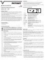
INSTALLATION
Fabricate a rectangular front plate opening with the following dimensions: 1.
W45.5mm x H22 mm for TCM220 or W68.5mm x H33 mm for TCM320.
Use a spirit level to achieve horizontal alignment.
Match opening with the module and then push gently on the front casing, not the LCD, until 2.
the module locks into place.
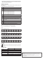
SOLDERPAD ASSIGNMENT
1. TH 1.1 Wire one of temperature probe for channel one
2. TH 1.2 Wire two of temperature probe for channel one
3. TH 2.1 Wire one of temperature probe for channel two
4. TH 2.2 Wire two of temperature probe for channel two
5. VDD key Common input for all push buttons
6. MIN/MAX Positive input for “MIN/MAX” key
7. PLUS Positive input for “PLUS” key
8. ALARM Positive input for “ALARM” key
9. GND Ground for operating voltage
10. VDD Operating voltage, +3 V
11. LED+ LED external voltage positive (3 V, 50 mA)
12. LED– LED external voltage negative
13. AL_HI_CH1 High temperature alarm signal for channel one (3 V; 2 mA)
14. AL_HI_CH2 High temperature alarm signal for channel two (3 V; 2 mA)
15. AL_LO_CH1 Low temperature alarm signal for channel one (0.2 V; 2 mA)
16. AL_LO_CH2 Low temperature alarm signal for channel two (0.2 V; 2 mA)
17. DATA_OUT Serial data out for current temperature
18. Clock Clock output
19. BUZ– Negative alarm output
20. BUZ+ Positive alarm output
x4 Close pads x4 and 11 for postive backlight voltage supply over internal
VDD
x12 Close pads x12 and 12 for negative backlight voltage supply over
internal VDD
CONNECTION
Solder the currentless wires of the battery pack’s (3 V/DC) power supply to the solder terminals
“VDD” (10) and “GND” (9).
Connect the module to a suitable keypad. For this, connect suitable connection wires to the
positive input of the keys “MIN/MAX“ (6), “PLUS“ (7) and “ALARM“ (8), and connect the other
ends of the wires to the solder terminal “VDD key“ (5).
For the LED, solder a connection wire from “VDD” (10) to the solder terminal “LED+” (11) and
from “GND” (9) to “LED–“ (12).
For connection to a computer, connect “GND“ (9) to the plug’s earthing terminal, “DATA_OUT“
(17) to the data transmission terminal and “CLOCK“ (18) to the data reception terminal.
OPERATION
If you have no keys connected to the module, you can make the settings by applying a
3 V/DC voltage to the solder terminals for a respective period of time.
By pressing any key following application of the voltage, the measurement interval for the •
temperatures of both channels that is automatically set to 10 seconds will be shortened to
2 seconds.
ToswitchbetweenChannel1(CH1)andChannel2(CH2),brieypressthe“PLUS“key.•
To display the stored minimum and maximum temperature of the selected channel, press •
the “MIN/MAX” key. When you press and hold the “MIN/MAX“ key for 3 seconds, the internal
MIN/MAX value is set to the actual temperature of the selected channel.
SETTING THE ALARM
Select the desired channel with the “PLUS” key.1.
Press and hold the “ALARM“ key for 3 seconds to enter the alarm setting mode. 2.
Press the “PLUS” key to set the lower temperature threshold. The temperature will be 3.
increased in 1°C increments from -30ºC to 70ºC.
Press the “ALARM“ key to move on to the upper temperature threshold setting. Proceed as 4.
with the lower temperature threshold.
Press the “ALARM“ key to exit the alarm settings. To exit the alarm setting mode immediately, 5.
press the “MIN/MAX“ key. The device will automatically exit the alarm setting mode when no
activity has been registered for 8 seconds.
Todisplay thelower/upper temperaturethreshold, brieypressthe“ALARM“key.If the6.
alarm is activated, the buzzer alarm will sound and a small icon will appear on the LED’s left
side to indicate what triggered the alarm. The respective alarm output (13, 14, 15 or 16) is
then set to high level (VCC).

The buzzer alarm can be turned off with any key. The alarm automatically turns off after 120 7.
seconds. The alarm output will be reset to low again once the temperature reading stays
within the preset temperature threshold range.
COMMUNICATION MODE
The module can connect to computer through serial connection. The RS232 Protocol for the
module is 9600.8.n.1
A complete data transmission cycle consists of 16 byte data:
Byte
0 Starting Byte with Constant value 0xAA
1 Starting Byte with Constant value 0xAA
2* Integer portion of the temperature value detected through CH1
3 Bit 0-3 – the decimal portion of the temperature value detected through CH1
Bit 4 – CH1 min. temperature alarm icon on/off (1/0)
Bit 5 – CH1 max temperature alarm icon on/off (1/0)
Bit 6 – CH2 min. temperature alarm icon on/off (1/0)
Bit 7 – CH2 max temperature alarm icon on/off (1/0)
4* Integer portion of CH1 preset min. temperature value
5 Decimal portion of CH1 preset min. temperature value
6* Integer portion of CH1 preset max. temperature value
7 Decimal portion of CH1 preset max. temperature value
8* Integer portion of the temperature value detected through CH2
9 Bit 0-3 – the decimal portion of the temperature value detected through CH2
Bit 4-7 not used
10* Integer portion of CH2 preset min. temperature value
11 Decimal portion of CH2 preset min. temperature value
12* Integer portion of CH2 preset max. temperature value
13 Decimal portion of CH2 preset max. temperature value
14-15 CRC Checksum = the sum of all the values from Byte 2 to Byte 13
The value 0xFF represent error or the sensor not connected
Bit 7 = 0, positive temperature. Bit 7 = 1, negative temperature.
Example
For 15.1°C, the integer portion is 0x15
Bit 7 Bit 6 Bit 5 Bit 4 Bit 3 Bit 2 Bit 1 Bit 0
0 0 0 1 0 1 0 1
and the decimal portion is 0x01
Bit 7 Bit 6 Bit 5 Bit 4 Bit 3 Bit 2 Bit 1 Bit 0
0 0 0 0 0 0 0 1
For -12.3oC, the integer portion is 0x92,
Bit 7 Bit 6 Bit 5 Bit 4 Bit 3 Bit 2 Bit 1 Bit 0
1 0 0 1 0 0 1 0
and the decimal portion is 0x03
Bit 7 Bit 6 Bit 5 Bit 4 Bit 3 Bit 2 Bit 1 Bit 0
0 0 0 0 0 0 1 1
DISPOSAL
Electronic devices are recyclable waste and must not be disposed of in the household
waste.
At the end of its service life, dispose of the product according to the relevant statutory
regulations.
TECHNICAL DATA
TCM 220 TCM 320
Input voltage: +3 V/DC
Current consumption: 20μAor50mA(withbacklighton)
Input channel: 2
Measure rate: 2 seconds or 10 seconds
Accuracy of measurement: ±1ºC
Resolution: 0.1ºC
Measuring temperature
range:
-30 to +70°C
Display: 3½ LCD, 10 mm digit height 3½ LCD, 14 mm digit height
Operating temperature range: -10 to +50°C
Dimensions (W x H x D): 48 x 24 x 15.5 mm 72 x 36 x 15 mm
Legal notice
These operating instructions are a publication by Voltcraft®, Lindenweg 15, D-92242 Hirschau/Germany, Phone +49 180/586 582 7
(www.voltcraft.de).
Allrightsincludingtranslationreserved.Reproductionbyanymethod,e.g.photocopy,microlming,orthecaptureinelectronicdataprocessing
systems require the prior written approval by the editor. Reprinting, also in part, is prohibited.
These operating instructions represent the technical status at the time of printing. Changes in technology and equipment reserved.
© Copyright 2012 by Voltcraft®
Page is loading ...
Page is loading ...
Page is loading ...
Page is loading ...
-
 1
1
-
 2
2
-
 3
3
-
 4
4
-
 5
5
-
 6
6
-
 7
7
-
 8
8


VOLTCRAFT TCM 220 Data Sheet
- Type
- Data Sheet
- This manual is also suitable for
Ask a question and I''ll find the answer in the document
Finding information in a document is now easier with AI
in other languages
- français: VOLTCRAFT TCM 220
- Deutsch: VOLTCRAFT TCM 220
- Nederlands: VOLTCRAFT TCM 220
Related papers
-
VOLTCRAFT FTPS 5-18W Operating instructions
-
-
-
-
-
-
-
VOLTCRAFT 19 73 39 Operating instructions
-
-
Other documents
-
Cross Technologies 582-10 Owner's manual
-
Samsung SHR-7082P Owner's manual
-
Samsung SHR-6082P Owner's manual
-
 Tecsis Manoport E3905 Operating instructions
-
Samsung SMO-150TP User manual
-
-
Bresser 7000012000000 Owner's manual
-
Pioneer VSX-330 User manual
-
Pioneer VSX-531D User manual
-
EuroLite LED PAR-64 COB User manual
